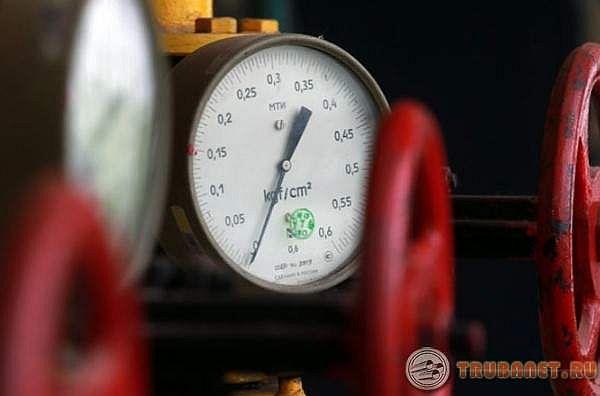
A pressure gauge is a device that measures the pressure of liquids and gases. Its principle of operation is based on balancing the action of a gaseous or liquid medium by the force of deformation of the membrane or spring. This device is one of the mandatory elements for controlling the parameters of most engineering communications. So, a pressure gauge for the heating system is needed to monitor the excess pressure inside the boiler and pipes (see Pressure in the heating system of a private house). At the same time, they are able to simply inform about the state of the coolant, and transmit a signal that blocks the operation of the equipment in order to prevent an emergency.
The purpose of hydraulic tests
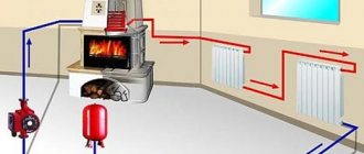
As a rule, any heating system operates in standard mode. The operating pressure of the coolant in low-rise buildings is mainly 2 atm, in nine-storey buildings - 5-7 atm, in multi-storey buildings - 7-10 atm. In a heat supply system laid underground, the pressure indicator can reach 12 atm.
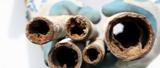
Sometimes unexpected pressure surges occur, which leads to an increase in pressure in the network. The result is a water hammer. Hydraulic testing of heating pipelines is necessary to check the system not only for its ability to function under standard normal conditions, but also for its ability to overcome water hammer.
If, for some reason, the heating system has not been checked, then serious accidents may occur subsequently due to hydraulic shocks, which will lead to the flooding of rooms, equipment, furniture, etc. with boiling water.
https://youtu.be/wyamZedWpzU
Under what conditions is it necessary to carry out a hydraulic check of pipelines?
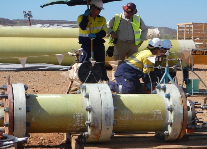
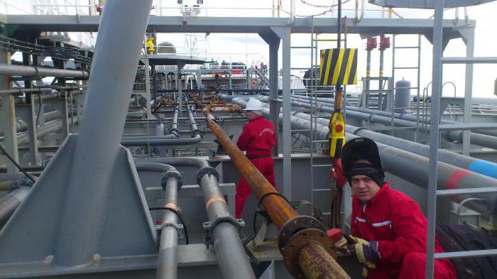
Hydraulic testing of pipelines is a complex activity that requires some preparation. The tests must be in accordance with building codes and regulations, therefore such checks are carried out only by highly qualified specialists.
The tests are carried out strictly according to the accepted norms and rules and the process is supervised by specialists.
To carry out such a check of the pipeline, the following conditions must be adhered to:
- the points of use in the riser are activated simultaneously for testing, however, this position is not always mandatory and is determined individually, depending on the specific case;
- the characteristics of devices for drying towels are checked when testing hot water systems;
- temperature measurements are carried out only at the extreme points in the structure;
- after carrying out the test work, it is necessary to completely remove water from the system;
- filling of communication is done from the bottom up. This rule is necessary for correct air displacement and avoids emergency situations associated with overpressure, as well as air congestion.
- the initial stage of filling the communication refers only to the main riser, and only at the next stages is the filling of the risers branching from the main one.
- during hydraulic tests, the ambient temperature must not be lower than +5 ° C.
These conditions must be met regardless of the type of pipeline and the working medium that it transports.
Hydraulic checks are carried out for the following equipment:
- internal fire water pipelines;
- hot and cold water supply systems;
- heating systems.
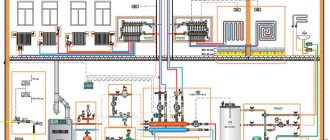
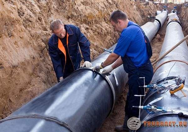
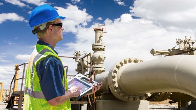
Different types of pipelines are tested, including heating and hot water networks
Sequence of work
Hydraulic testing of pipelines should be carried out in the following sequence.
- Cleaning of pipelines.
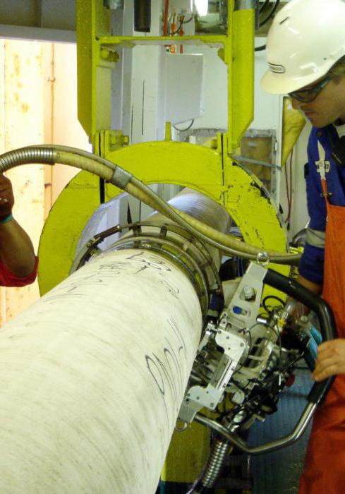
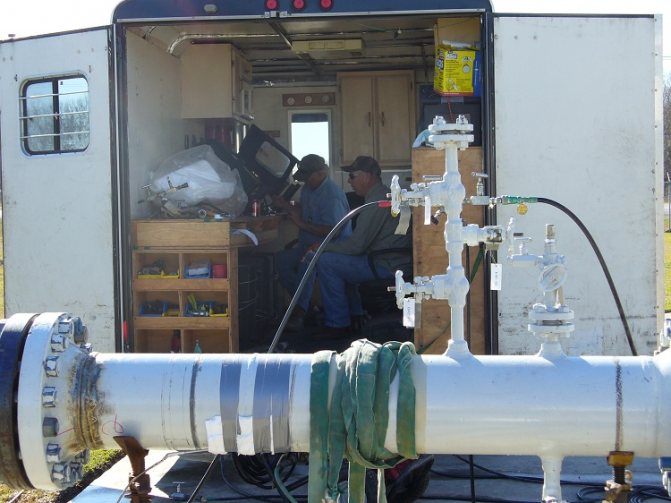
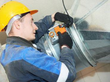
- Installation of taps, plugs and pressure gauges.
- Water and hydraulic press are connected.
- The pipelines are filled with water to the required value.
- Inspection of pipelines and marking of places where defects were found are carried out.
- Elimination of defects.
- Conducting a second test.
- Disconnection from the water supply and drainage of water from pipelines.
- Removing the plug and gauges.
Hydrotesting procedure of technological pipelines
Hydraulic testing of technological pipelines is done in order to determine the density during embossing and leaks in the pipeline. For the first time, the network is tested before filling the recesses and installing the fittings.
The subsequent test is carried out at the final stage after the complete backfilling of the trenches and the end of operations in this section of technological systems. Pre-testing can be carried out when the joints are gaining the required strength.
It is considered that any of the technological pipelines has passed the control, if there has not been a rupture in it and the tightness has not been broken. Also, if the joints remain intact, and no leaks have formed.
Upon completion of the testing of technological systems, they are immediately covered with earth and the final testing is performed. During this event, the technological systems are flushed with water, and the areas to be checked are cut off from the functioning system by means of flanges or plugs.
Before testing, the network and socket joints are poured with water and allowed to stand for 24 hours. The final test is carried out without safety valves and hydrants. Instead, they put stubs.
In this case, the valves are fully opened, only first they check the condition of the stuffing box packing. It is impossible to use gate valves to cut off the tested zone from the functioning one.
Preparatory work
Before performing hydraulic tests of pipelines of heating systems, it is necessary to revise all valves, fill glands on the valves. Insulation is being repaired and checked on pipelines. The heating system itself must be separated from the main pipeline by means of plugs.
After completing all the necessary manipulations, the heating system is filled with water. With the help of pumping equipment, excess pressure is created, its indicator is about 1.3-1.5 times higher than the working one. The resulting pressure in the heating system should be kept for another 30 minutes. If it has not decreased, then the heating system is ready for operation. Acceptance of works on hydraulic tests is carried out by the inspection of heating networks.
The main stages of testing
Hydraulic tests are carried out in several stages:
- A pump for water supply is brought in.
- Install pressure gauges.
- Fill the system with water. During this time, the air vents remain open until water appears in them. This will be an indication that air has been removed from the system. During the filling of the system, the pipes are inspected for leaks and structural defects.
- Forcing the system to operate at elevated pressure using a pump for a while.
- Reduce pressure to working norm.
- Remove water from the pipes, inspect the system again.
- Remove the pressure gauges and remove the pump.
It takes five minutes to test the network under pressure. Only glass pipelines are tested for twenty minutes.
Reference! When viewing steel pipelines, welded joints are tapped with a rounded hammer on both sides of the joint. The weight of the hammer is about 1.5 kilograms. Nets made with non-ferrous metal are checked with a wooden mallet weighing about 700 grams. It is impossible to tap the lines made with the help of other materials.
Strength
- The pressure in the pipeline is increased to the test pressure (Pi) by pumping water and maintained for 10 minutes. The pressure must not be allowed to drop above 1 kgf / m2 (0.1 MPa).
- The test pressure is reduced to the calculated (Pр) internal, then it is maintained by pumping water. The pipelines are inspected for defects over the time required to carry out this inspection.
- The detected defects are eliminated, after which a repeated hydraulic test of the pressure pipeline is carried out. Only then can the tightness test be started.

Tightness
- The pressure in the pipeline rises to the test value for tightness (Pg).
- The start time of the test (Tn) is recorded, the initial water level (hn) is measured in the measuring tank.
- After that, the decrease in the pressure indicator in the pipeline is monitored.
There are three options for the pressure drop, we will consider them.
The first
If, within 10 minutes, the pressure indicator decreases by less than 2 marks on the pressure gauge scale, but does not fall below the calculated internal (Pр), then the observation can be completed.
Second
If, after 10 minutes, the pressure value drops by less than 2 marks on the pressure gauge scale, then in this case, monitoring the decrease in pressure to the internal (Pр) calculated pressure must be continued until it drops by at least 2 marks on the pressure gauge scale.
The duration of observation for reinforced concrete pipes should not exceed 3 hours, for cast iron, steel and asbestos-cement pipes - 1 hour. After the specified time has elapsed, the pressure must drop to the design pressure (Pр), otherwise the water is discharged from the pipelines into the measuring tank.
Third
If within 10 minutes the pressure becomes less than the internal design pressure (Pр), then further hydraulic tests of heating pipelines must be suspended and measures must be taken to eliminate hidden defects by maintaining the pipes under the internal design pressure (Pр) until a thorough inspection reveals defects that will cause an unacceptable pressure drop in the pipeline.
Pipeline test pressure
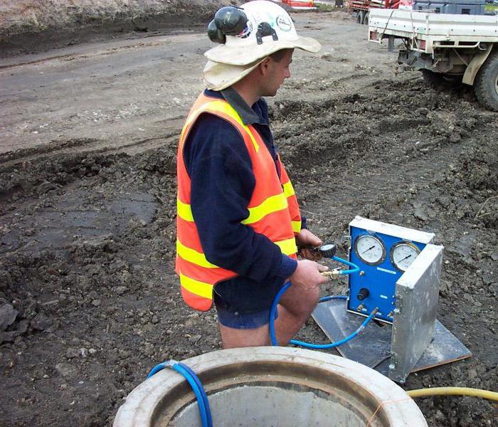
The pressure during hydrotesting of pipelines is checked with manometers, they must first be checked and sealed.
According to GOST 2405-63, these mechanisms must be characterized by an accuracy class of at least 1.5. The volume of their body cannot be less than 15 cm, and the scale for the nominal pressure indicator must be at least three quarters of the measured one.
By hydrotesting, the systems are tested not only for the level of strength, but also for density. In this case, the number of test pressure is chosen differently. For example:
- Steel and cast iron systems of a pressure type - for them the indicator prescribed in the project is a coefficient of 1.25. The rise of the test pressure above the operating level cannot exceed 5 kg / cm2, and the level of the test pressure cannot exceed 10 kg / cm2.
- Pressure-type asbestos-cement systems are not higher than the working pressure level by 5 kg / cm2.
- Polymer systems are tested under a pressure specified by GOST or TU for a certain type of pipes, and this indicator is not allowed to be reduced below the operating level.
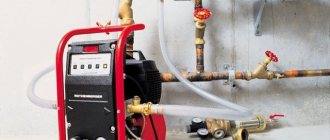
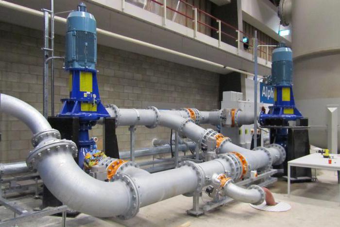
To create the required pressure during hydrotesting use:
- Hydraulic presses.
- Hand-operated piston pumps.
- Drive gear pumps.
- Operational pumps.
Determination of the additional volume of water
After completing the observation of the drop in the pressure indicator according to the first option and stopping the discharge of the coolant according to the second option, the following should be done.
- By pumping water from a measuring tank, the pressure in the pipeline is increased to the value during hydraulic tests (Pg).
- Remember the time when the tightness test (Tk) ended.
- Next, you need to measure the final water level hk in a measuring tank.
- Determine the duration of testing pipelines (Tk-Tn), min.
- Calculate the volume of water pumped up from the measuring tank Q (for option 1).
- Determine the difference between the volumes of pumped and discharged water from the pipelines or the amount of additionally pumped water Q (for the 2nd option).
- Calculate the actual flow rate of additionally pumped water (qn) using the following formula: qn = Q / (Tk-Tn)
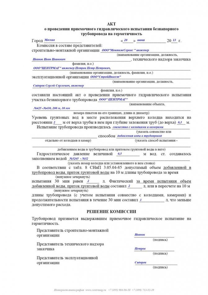
Drawing up an act
The certificate that all work has been carried out is the act of hydraulic testing of pipelines. This document is drawn up by the inspector and confirms that the work was carried out in compliance with all norms and rules, and that the heating system withstood them successfully.
Hydraulic testing of pipelines can be carried out in two main ways:
- Gauge method - tests are carried out by means of manometers, devices that record pressure indicators. During operation, these devices show the current pressure in the heating system. Hydraulic testing of pipelines by means of a pressure gauge allows the inspector to check what the pressure was during testing. Thus, the operating engineer and inspector check how reliable the tests performed are.
- The hydrostatic method is considered the most effective, it allows you to check the heating system for operability at a pressure that exceeds the average operating indicator by 50%.
Various elements of the system are tested for different times, while hydraulic testing of pipelines cannot last less than 10 minutes. In heating systems, the permissible pressure drop is considered to be an indicator of 0.02 MPa.
The main condition for the beginning of the heating season is competently conducted and properly executed hydraulic tests of pipelines (SNiP 3.05.04-85), in accordance with the requirements of the current regulatory documentation.
SP 40-102-2000: Testing and commissioning of pipelines
Introduction Scope of application General provisions Design of internal water supply networks Design of internal sewerage and waterways Design of an external water supply Design of an external sewerage, gutters and drainages Installation of pipelines
8.1 According to SNiP 3.05.04, pressure and non-pressure water supply and sewerage pipelines are tested for strength and tightness (tightness) hydraulically or pneumatically twice (preliminary and final).
8.2 The preliminary test (excess) hydraulic pressure during the strength test, performed before backfilling the trench and installing the fittings (hydrants, safety valves, plungers), must be equal to the design working pressure multiplied by a factor of 1.5.
8.3 The final hydraulic test pressure for density tests performed after backfilling of the trench and completion of all work on this section of the pipeline, but before installing hydrants, safety valves and plungers, instead of which plugs are installed during the test, should be equal to the calculated working pressure multiplied by coefficient 1.3.
8.4 Prior to testing pressure pipelines with socket connections with O-rings, temporary or permanent stops should be arranged at the ends of the pipeline and on branches.
8.5 Preliminary hydraulic test of pressure pipelines should be performed in the following order:
- fill the pipeline with water and hold it without pressure for 2 hours;
- create a test pressure in the pipeline and maintain it for 0.5 h;
- reduce the test pressure to the design pressure and inspect the pipeline.
Holding the pipeline under the operating pressure is carried out for at least 0.5 hours. Due to the deformation of the pipeline shell, it is necessary to maintain the test or operating pressure in the pipeline by pumping water until complete stabilization.
The pipeline is considered to have passed the preliminary hydraulic test if no ruptures of pipes or joints and fittings are found under the test pressure, and no visible water leaks are found under the operating pressure.
8.6 A final hydraulic tightness test is carried out in the following order:
- in the pipeline, create a pressure equal to the design working pressure, and maintain it for 2 hours; when the pressure drops by 0.02 MPa, water is pumped;
- the pressure is raised to the test level for a period of not more than 10 minutes and maintained for 2 hours.
The pipeline is considered to have passed the final hydraulic test if the actual water leakage from the pipeline at the test pressure does not exceed the values specified in Table 5.
8.7 Hydraulic tests of gravity sewer networks are performed after the completion of waterproofing works in wells in two stages: without wells (preliminary) and together with wells (final).
8.8 The final test of the sewage pipeline together with the wells is carried out in accordance with SNiP 3.05.04.
8.9 Hydraulic tests of systems made of polymeric materials of internal pipelines are carried out at a positive ambient temperature not earlier than 24 hours after the last welded and glued joint.
8.10 Hydraulic tests of internal drainage systems are carried out by filling them with water to the entire height of the risers. Tests are carried out after external inspection of pipelines and elimination of visible defects. Hydraulic testing of glued pipelines begins no earlier than 24 hours after the last connection. The drainage system is considered to have passed the test if, after 20 minutes after its filling, an external inspection of the pipelines did not reveal a leak or other defects and the water level in the risers did not drop.
8.11 Pneumatic tests of pipelines made of polymeric materials are carried out during their above-ground and above-ground laying in the following cases: the ambient air temperature is below 0 ° С; the use of water is unacceptable for technical reasons; there is no water in the amount required for testing.
The procedure for pneumatic testing of pipelines made of polymeric materials and safety requirements during testing are established by the project.
8.12 Preliminary and final tests of gravity sewer networks from large-diameter pipes are allowed to be carried out pneumatically. Preliminary tests are carried out before the final backfilling of the trench (welded joints are not covered with soil). The test pressure of compressed air, equal to 0.05 MPa, is maintained in the pipeline for 15 minutes. At the same time, welded, glue and other joints are inspected and leaks are detected by the sound of leaking air, by bubbles formed in places where air leaks through butt joints covered with a soap emulsion.
The final pneumatic tests are carried out at a groundwater level above the pipe in the middle of the tested pipeline of less than 2.5 m.Final pneumatic tests are carried out on sections with a length of 20-100 m, while the difference between the highest and lowest points of the pipeline should not exceed 2.5 m. Pneumatic tests are carried out 48 hours after filling the pipeline.The test overpressure of compressed air is shown in table 6.
| Outside diameter of pipes, mm | Permissible leakage, l / min, for pipes | |
| with permanent (welded, adhesive) joints | with socket connections on O-rings | |
| 63-75 | 0,2-0,24 | 0,3-0,5 |
| 90-110 | 0,26-0,28 | 0,6-0,7 |
| 125-140 | 0,35-0,38 | 0,9-0,95 |
| 160-180 | 0,42-0,6 | 1,05-1,2 |
| 200 | 0,56 | 1,4 |
| 250 | 0,7 | 1,55 |
| 280 | 0,8 | 1,6 |
| 315 | 0,85 | 1,7 |
| 355 | 0,9 | 1,8 |
| 400-450 | 1,1-0,5 | 1,95-2,1 |
| 500-560 | 1,1-1,15 | 2,2-2,3 |
| 630 | 1,2 | 2,4 |
| 710 | 1,3 | 2,55 |
| 800 | 1,35 | 2,70 |
| 900 | 1,45 | 2,90 |
| 1000 | 1,5 | 3,0 |
| 1200 | 1,6 | 3,0 |
| Groundwater level h | Test pressure, MPa | Pressure drop, | |
| from the pipeline axis, m | excess initial p | final p1 | p - p1, MPa |
| h = 0 | 0,01 | 0,007 | 0,003 |
| 0 | 0,0155 | 0,0124 | 0,0031 |
| 0,5 | 0,021 | 0,0177 | 0,0033 |
| 1 | 0,0265 | 0,0231 | 0,0034 |
| 1,5 | 0,032 | 0,0284 | 0,0036 |
| 2 | 0,0375 | 0,0338 | 0,0037 |
8.13 Acceptance of pipelines for operation must be carried out in accordance with the basic provisions of SNiP 3.01.04, as well as SNiP 3.05.04. When testing water supply and pressure sewerage pipelines and putting them into operation, the following should be drawn up:
- acts for hidden work (on the base, supports and building structures on pipelines, etc.);
- acts of external inspection of pipelines and elements (nodes, wells, etc.);
- test reports for strength and density of pipelines;
- acts for flushing and disinfection of water pipelines;
- establishing the compliance of the work performed with the project;
- acts of incoming quality control of pipes and fittings.
8.14 In addition to accepting hidden works and checking certificates for testing pipelines for density and external inspection, acceptance of free-flow pipelines should be accompanied by a check of straightness, as well as an instrumental check of trays in wells.
When accepting internal water pipelines, passports or certificates for polymer pipes, fittings and fittings are additionally checked.
Safety precautions when installing pipes made of polymer materials Transportation and storage of pipes made of polymer materials Appendix A Appendix B Appendix C Appendix D Appendix E Appendix E