Pipeline network
The product moves between the units of the plant along the pipeline network.
The dairy also has conductive systems for other media - water, steam, cleaning solutions, refrigerant and compressed air. The presence of a wastewater disposal system is also imperative. All these systems do not differ in principle from each other. The only difference is in the materials from which they are made, in the design of the parts and in the dimensions of the pipes.
All parts in contact with the product are made of stainless steel. Other systems use different materials - for example, cast iron, steel, copper, aluminum. Plastics are also used for the manufacture of water and air lines, and ceramics for drainage and waste pipelines.
In this section, we will only talk about the product piping and its parts. Auxiliary piping is described in the section on auxiliary equipment.
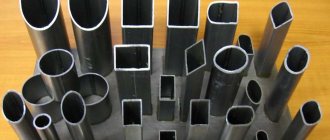
The product piping system includes the following fittings: • Straight pipes, elbows, tees, reducers and couplings
• Special fittings - sight glasses, instrument elbows, etc.
• Valves for stopping and changing direction of flow
• Pressure and flow control valves
• Brackets for pipes.
For hygiene reasons, all parts in contact with the product are made of stainless steel. There are two main grades used: AISI 304 and AISI 316. The latter is often referred to as acid resistant steel. The following grades of Swedish steel correspond (although not completely) to them:
| USA | AISI 304 | AISI 316 | AISI 316L |
| Sweden | SIS 2333 | SIS 2343 | SIS 2359 |
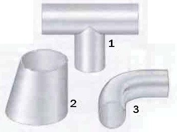
Fig. 1 Some types of fittings that are welded into pipelines. 1 Tees 2 Reducers 3 Elbows
Valve and types of pipeline fittings
Virtually any kind of fittings have found their constructive embodiment in valves. The valves are present in all types of fittings according to their intended purpose and scope: general industrial, sanitary, reduction, control, power and others. A safety valve made in the form of a valve is called a safety valve, a check valve is a check valve, a control valve is a control valve, etc.
There are shut-off, mixing, distribution, dividing, shut-off, shut-off valves. Valves are an integral part of the design of a significant part of technical devices ─ representatives of phase separation valves.
The safety valve serves to automatically protect equipment and pipelines from unacceptable overpressure by dumping excess working medium. Non-return valve ─ to automatically prevent backflow of the medium. Control valve ─ to regulate its parameters by changing the flow rate or flow area.
An example of a check valve is a foot valve installed at the end of the pipeline upstream of the pump.
A type of control valve is a breathing valve (other names are an inlet or outlet valve), designed to seal containers that contain gas, air or steam. Also an integral part of the control valves is a bypass valve, which serves to periodically reduce the pressure in the pipeline and equipment "upstream" in case of exceeding the set value.
Connections
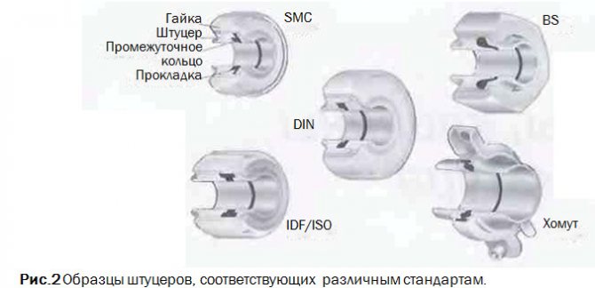
Permanent joints are welded (Fig. 1). There. where undocking is required, the connection is usually made in the form of a threaded nipple, onto which an intermediate ring is slid and a lock nut screwed on, or as a nipple with an intermediate ring and a clamp (fig. 2).
The presence of a union allows undocking without disturbing other parts of the pipeline. Therefore, this type of fittings is used to connect elements of technological equipment, instruments, etc., which sooner or later have to be removed for cleaning, repair or replacement.
Different countries have different standards for fittings.These standards include SMS (Swedish Standard for Dairy Equipment), which is also internationally recognized, DIN (Germany), BS (England), IDF / ISO * and ISO Clamps (widely used in the USA).
Elbows, tees and similar fittings are available, allowing installation by welding and having places for welding. In the latter case, the fittings can be ordered with a nut or inner part of the connection, or with a tightening connector.
All fittings must be properly sealed to prevent fluid leaks from the system or air being drawn into the system, which will cause problems in the downstream process.
Special fittings
Sight glasses are installed in-line in those places where a visual check of product availability is necessary.
Elbows with fittings for devices are used to install thermometers and manometers. The sensor should be installed upstream to provide the most accurate reading. Special nubs are designed for inserting sampling valves. Instrument connections can also be fitted with special sockets for welding directly to the pipe during installation.
Fig. 3. Sampler.
Fig. 4 Plug for sampling for microbiological analysis.
Sampler
Such fixtures should be installed at strategic points on the production line to sample products for analysis. For quality control purposes, such as determining the fat content of milk or the acidity (pH) level of fermented milk products, samples can be taken using the sampler shown in Figure 3.
When determining the sanitary condition of the production line, the practiced sampling method should completely eliminate the risk of introducing any contamination from the external environment into the pipe. For this purpose, a suction plug is used (see Fig. 4). There is a rubber plug at the bottom of this plug. First, the stopper is removed and all parts of the stopper that could introduce any contamination into the sample are thoroughly disinfected (usually with a swab soaked in a solution containing chlorine just prior to sampling). After that, a needle of a medical syringe is inserted into the product through a rubber plug and a sample is taken with it.
Samples of aseptic products (heat treated at temperatures so high that they are virtually sterile) are always sampled through an aseptic sampling valve to prevent reinfection.
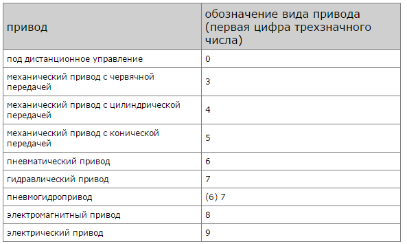
Types and types of check valves
- Disc check valve. The product is easy to install and inexpensive. The principle of operation is based on the displacement of the butterfly valve along the direction of fluid movement.
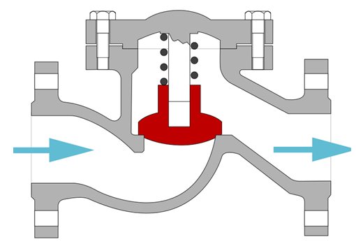
- Reverse-acting lift valve. Designed for pipelines through which compressed air and steam are transported. Differs in high locking strength.
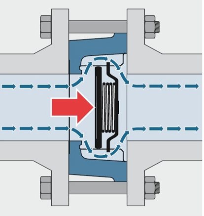
- Ball type check valve. Provides high throughput due to the simple shape of the flow path with a high closing density. Performance and low requirements for the qualitative composition of the liquid make it possible to use the device in pipelines for cold, viscous or inhomogeneous substances.
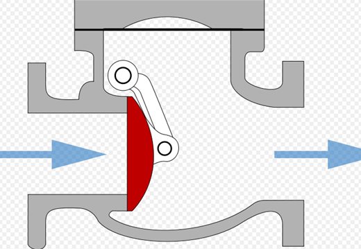
- Swing check valve. A steel disc of radial displacement type is used as a locking element. The fittings are used for installation in pipelines serving heating points, boiler houses, as well as at industrial facilities.
The popularity of the use of valve devices of the reverse principle of action is caused by:
- simplicity of design;
- trouble-free operating principle;
- reliable tightness;
- functional efficiency;
- low cost for long-term intensive operation.
In addition, some types of check valves are designed for special operating conditions.For this purpose, design features have been developed, thanks to which it is possible to select piping equipment that more closely matches the conditions of use, for example, when connecting pipelines to boiler rooms. This is due to the fact that sharp pressure drops often occur in heating mains.
For this, shock and shockless check valves are provided. If the diameter of the device is not more than 400 mm, shock processes do not have a significant effect on the operation and the system as a whole.
To mitigate shock phenomena in large pipelines, hydraulic dampers or counterweights are used to withstand the sudden shock. The disadvantage is that shock check valves are mounted only on horizontal sections of heating mains. Benefits include less sensitivity to polluted aquatic environments.
Wafer-type check valve APA.ZO View
Check valve RF 6666
Look
Reverse shutter RF 8686
Look
Valves. Valve systems
There are many joints in the pipeline network through which the product flows from one line to another, but which sometimes have to overlap so that two streams of different fluids can move along these two lines without mixing with each other.
When the lines are isolated from each other, any leakage must go to the drain, and any possibility of one liquid entering another must be excluded.
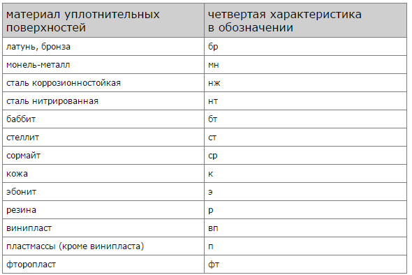
This is a common problem in the design of dairy plants. Dairy products and cleaning solutions are fed through different pipelines and must not touch. Figure 5 shows four possible solutions to this problem.
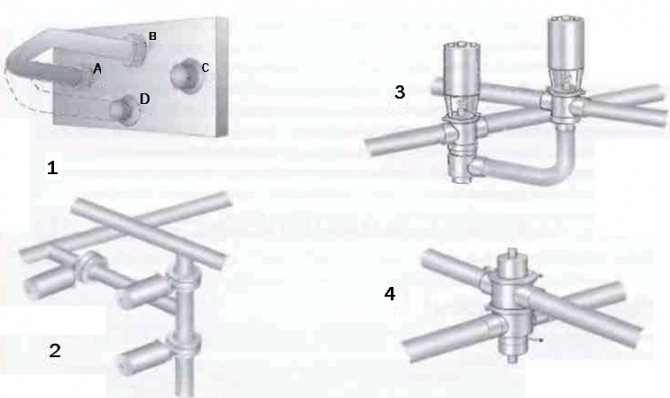
Fig. 5 Mixture valve systems used in the food industry. 1 Swivel elbow to manually switch flow to another channel 2 Three shut-off valves can perform the same function 3 One shut-off valve and one change-over valve can do the same job 4 One mixproof valve is sufficient to shut off and change the flow
Globe valves
The valve body has a valve stem seat at the end of the stem. A stem, which is actuated by a crank or pneumatic mechanism, lifts the valve off the seat and lowers it back (see figure 6).
Fig. 6 Manual seated shut-off valve and pneumatic seated changeover valve. The shut-off and changeover valve actuators are interchangeable.
The seated globe valve is also available as a change-over version.
This valve has three to five holes. When the valve is lowered, fluid flows from inlet 2 to outlet 1, and when the valve is raised to the upper seat, flow is directed through outlet 3, as shown in figure 7.
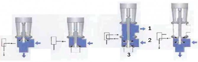
Fig. 7 Shut-off and changeover valves with different core positions and corresponding designations on the process chart.
This type of valve can have up to five holes. Their number is determined by technological requirements.
Remote controlled actuators are available in a variety of options. For example, a valve can be opened with compressed air and closed with a spring, or vice versa. It can also be opened and closed with compressed air (see fig. 8).
Fig. 8 Examples of pneumatic actuators. 1 Valve opens with spring and closes with compressed air 2 Valve closes with spring and opens with compressed air
Actuators are also available for intermediate valve positions and for two-stage opening and closing.
The valve control (fig. 9) is often installed as a block on the valve actuator. This block contains valve position sensors that send information to the main control system.A solenoid valve is built into the air duct to the valve actuator or to the control unit. An electrical signal activates the solenoid valve and allows compressed air to enter the actuator. This causes the valve to open or close as required. When supplied, compressed air passes through the filter, freeing of oil and other contaminants that can interfere with the proper operation of the valve. When the solenoid valve is turned off, the air supply is cut off and air is removed from the valve on the product pipe, through the outlet in the solenoid valve.
Fig. 9 Valve plug position indicator mounted on the actuator.
Valve actuators
To control the valves ─ movement of the locking or regulating element ─ various actuators are used: manual, electric, electromagnetic, hydraulic, pneumatic, or their combinations.
Examples of a combined drive are a pneumatic hydraulic drive using compressed gas and hydraulic power and an electro-hydraulic drive.
The transfer of translational force from the drive to the locking or regulating element is carried out by means of a rod (spindle).
Electric actuators are widely used to control control valves in heating, ventilation and air conditioning systems. A modern electric drive is a complex technical device that includes a control system, an electric motor and a gearbox.
If in an electric drive, electrical energy is used "directly", then in an electromagnetic drive, its transformation into mechanical energy occurs as a result of the interaction of an electromagnetic field and a core made of ferromagnetic material.
A solenoid valve equipped with an integral or remote solenoid actuator is a common design.
Solenoid valves can be operated from alternating current from centralized electrical networks or from direct current from independent sources ─ batteries or direct current generators.
Solenoid valves are widely used in instrumentation; to control the processes of dosing, shutdown, mixing, dumping, distribution of flows of working media.
For many years, pneumatic actuators have been used to control valves, applicable to almost all but the largest valve sizes, where a hydraulic actuator capable of delivering high torque comes in handy.
The use of actuators makes it possible to automate the operation of the valves. Requirements for valve actuators: guarantee of the required operating range values (output torque), wear resistance, tightness, compliance with safety requirements, corrosion resistance.
Gate valves
The gate valve (in Fig. 10) is a shut-off valve. For switching operation, two valves must be used.
Gate valves are often used when working with products that are susceptible to mechanical stress - yoghurt and other fermented milk products, since the hydraulic resistance of the valve is small, and, therefore, the pressure drop across the valve and turbulence are negligible. These valves are very good for high viscosity products and as a straight-through valve they can be installed on straight pipe runs.
A valve of this type usually consists of two identical flaps, between which an o-ring is installed. A streamlined disc is located in the center of the valve. It usually rests on bushings to keep the stem from rubbing against the valve body.
When the disc is in the open position, the valve offers very little flow resistance. In the closed position, the disc is sealed with a rubber ring.
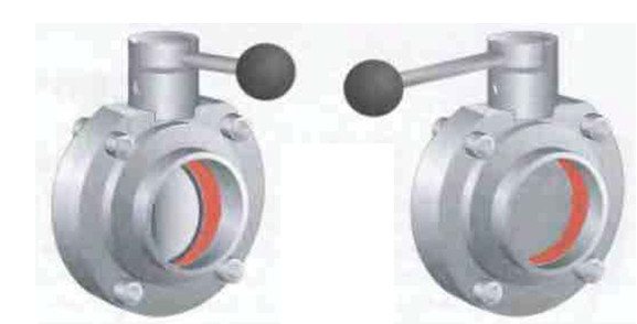
Fig. 10 Manual gate valve in open (left) and closed (right) position.
Scope of use of check valves
The check valve has two functional tasks. It restricts the reverse movement of the transported medium in the normal operation of the pipeline, which is required when installing a system of several lines, each of which is connected to a separate circulation pump.
If an emergency occurs in such a pipeline and one of the pumps fails, but the pressure on the adjacent lines remains, the valve will protect the system from water hammer, which can cause damage to the functioning equipment.
This type of protective reinforcement is used in the following cases:
- when installing pipelines with closed circulation of the working environment (heating system);
- when completing the pipeline with several circulation pumps, in order to prevent their impact on each other during simultaneous operation;
- in filtration systems on industrial reverse pipelines to ensure the movement of liquid through the filter in a given direction;
- in pipelines of any type (sewage, water supply systems), where one-way flow is required.
The location of the check valve on the pipeline
All types of protective fittings are classified into two main groups:
- check valves;
- back locks.
The differences between them lie in the design of the locking mechanism - in the valves it is represented by a spool, while in the valves a round (one or two-leaf) disc is used, called “slamming”. The valves are designed for installation on horizontal pipelines, valves - on vertical ones.
Depending on the design, the valve can be parallel (straight through) or angular, changing the direction of the line to 900. The valves are made exclusively in a parallel configuration.
How to choose a water check valve? (video)
Product marking
According to the provisions of TsKBA (Central Design Bureau of Valves), check valves are marked as 19s53nzh, wherein:
- 19 - rotary type check valve;
- c - made of carbon steel;
- 5 - mechanical drive;
- 3 - model number;
- nzh - with stainless steel sealing surfaces.
In this marking, the first number (19) indicates the type of fittings, the following number is the designation of the material of manufacture according to the table:
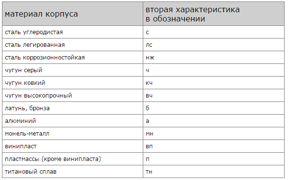
Nomenclature of materials of manufacture
The number following the body material nomenclature indicates the type of actuator.
Valve Actuator Type Nomenclature
The last letter designation indicates the material of manufacture of the sealing elements.
Nomenclature of the brand of the sealing element
Automatic control
An air drive is used for automatic control of the slide gate (Fig. 11). The following operating modes are possible:
• Spring to close / air to open (valve closed in neutral position)
• Spring open / air close (valve open in neutral position)
• Air opening and closing.
The disc rotates easily until it touches the O-ring. Further, more force is required to compress the rubber. A conventional spring-type actuator produces maximum force at the start of travel when minimum force is required,
and at the end of the stroke, when the effort should be greater, it just weakens. Therefore, it is preferable to use drives that provide the required force at every moment of operation.
Another type of gate valve is a flanged valve (see fig. 12).
In fact, it is similar to the already described type of gate valve, but differs in that it is fixed between two flanges welded to the pipeline. It functions in the same way as a conventional gate valve.During operation, it is screwed to the flanges. During maintenance, the screws are loosened and the valve can be easily removed for work.
Fig. 11 The principle of operation of the air drive of the slide damper.
Fig. 13 Two-seat plug-in, balanced-plug valve with integral movable seat. 1 Actuator 2 Upper port 3 Upper plug 4 Drain chamber 5 Hollow shaft connecting to atmosphere 6 Lower port 7 Bottom plug with balance
Advantages and Disadvantages of Flanged Type Check Valves
Since flange-type check valves are most often used to equip pipelines through which the working medium is transported with high intensity, the internal elements of such devices (in particular, the locking mechanism) experience significant shock loads during operation. In addition, the flange-type check valve, due to its significant dimensions, itself is the cause of water hammer. In the process of closing the valve flaps in the pipeline in which it is installed, the pressure inevitably rises, which leads to the formation of a water hammer.
In those pipeline systems in which water hammer is not able to significantly affect the performance of both individual elements and the system as a whole, simple type check valves are used. The diameter of the latter, as a rule, does not exceed 400 mm. In other cases, shockless check valves are used. Smooth and soft closing of the shut-off element in bumpless flanged valves can be provided by special weights or hydraulic dampers. Meanwhile, when choosing non-shock type check valves for equipping a pipeline system, it should be borne in mind that they can be installed only in horizontal sections.
Flanged Axial Shockless Valve
The most significant advantages of flanged check valves include:
- compact dimensions, which makes it possible to install such devices in almost any section of the pipeline system;
- the ability to work effectively even in those systems in which the working environment is characterized by severe pollution;
- the possibility of installation on pipelines with a large diameter.
Mixproof valves
Valves of this type (fig. 13) can be single or double-seated, but here we will talk about the double-seated option (fig. 13) as more typical for this type of valve.
The double-seated valve has two independent seats with a drainage chamber between them. This chamber must be vented to provide complete guarantees against mixing flows in the event of a leak in one of the seats. When the double seat valve is commanded to operate, the chamber between its upper and lower bodies is closed, then the valve opens, connecting the upper and lower pipelines. When the valve is closed, first the upper valve plug cuts off the liquid supply from the upper pipeline, and then the drainage chamber communicates with the atmosphere. This does not result in any significant product loss during operation.
It is important that the lower plug is hydraulically balanced to avoid opening the valve and subsequent mixing of fluids as a result of water hammer.
During washing, one of the valve closures opens or an external CIP line is connected to the drain chamber. Some valves can be connected to an external source to clean those parts of the valve that have been in contact with the product.
A single seat non-mixing valve has one or two seats, but for the same plug. The space between the two cores communicates with the atmosphere. Before this valve starts to operate, this drainage chamber is closed by small check valves.When flushing is required, an external CIP line is connected to the drain chamber through these valves.
Fig. 14 Three types of non-mixing valves. 1 Double-seat valve with a washer for a movable seat 2 Double-seat valve with an external wash 3 Single-seat valve with an external wash
Varieties of check valves
Depending on the design, check valves are classified into:
- ball;
- spool valves;
- disk;
- air and vacuum.
Spool valve diagram
The most common options are designs in which a spool is used as a shut-off element. The shut-off unit is installed in a vertical position, its opening is performed due to the pressure of the flow of circulating water, while the spool is lowered under its own weight, which makes it possible to install such products exclusively on horizontal sections of pipelines.
Ball valve diagram
If it is necessary to install vertical systems, ball valves with an additional clamping element - a spring are used. Such products are mainly used for plumbing pipes of small diameter (up to 50 mm).
Disc valves, depending on the type of design, are flap or spring-loaded. In folding products, the locking mechanism is represented by a flap, the axis of which coincides with the direction of movement of the flow circulating through the pipes. Under the pressure of the working medium, the sash moves at a certain angle, thereby opening the passage for water, and when circulation stops, the sash returns to its original position under its own weight.
Flap valve diagram
In spring-type butterfly valves, a flow-moving check disc in the seat compresses the spring, thereby opening the bore for circulation. When the pressure of the working medium decreases, the spring expands and returns the disc back. Such products can be installed on both vertical and horizontal pipelines. They are designed for installation on pipes of large diameter - from 110 mm.
Spring valve diagram
The butterfly valve has a shut-off mechanism that folds under flow pressure and opens when the circulating medium moves backward. The diameter of such products varies in the range of 50-700 mm. The household butterfly valve is not used.
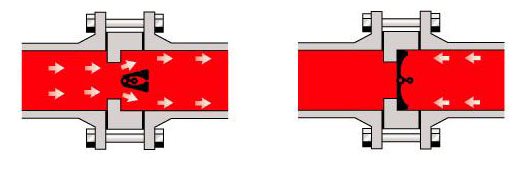
Diagram of a two-leaf valve
Air check valves
There is a separate class of products intended for installation in sewer systems. They are mounted on a riser and prevent the discharge of sewage gases into the room through the toilet bowl drain.
Depending on the design, the air valve can be:
- membrane;
- vacuum.
Membrane structures restrict air movement due to a rubber membrane that has a one-way opening. When the water is drained, it opens under the pressure of the flow, and the stops and stops do not allow it to move in the opposite direction and let the sewer gases pass.
The vacuum valve, which performs the function of pressure stabilization, is installed in sewage systems that are not equipped with a ventilation pipe. Its design consists of three elements - an air intake chamber, a stem and a double-sided membrane.
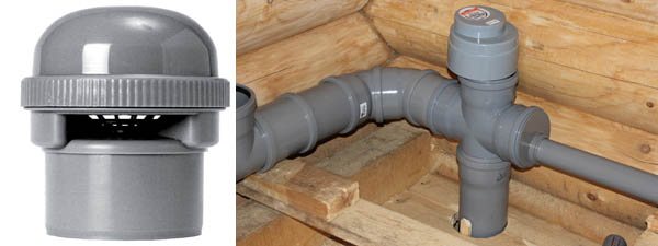
Vacuum Sewer Valve
When the pressure in the riser rises, the stem raises the rubber membrane, thereby releasing excess air from the system. In the event of the formation of reduced pressure, the membrane opens inward, thereby allowing the amount of air necessary to stabilize the system.
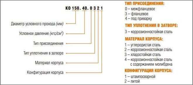
Separately, we note the pneumatic valve used in the chemical, oil and gas and automotive industries.The pneumatic valve has the KPO designation; it is available in diameters of 7, 10, 16 and 20 mm.
Technical characteristics of KPO valves:
- nominal pressure: 1-10 kgf / cm2;
- opening pressure of the locking mechanism - 0.2 kgf / cm2;
- operating temperature - 40 +80 degrees.
Technological features of installation
Depending on the method of installation on the pipeline, the valve can be:
- coupling - mounted by means of a threaded connection on pipes with a diameter of not more than 50 mm;
- flanged - installed using bolts and fixing nuts threaded into the seats - flanges (for technical pipelines of large diameter - 110 mm and more);
- wafer - clamped between the connecting flanges of the pipe line;
- welded - installed by arc welding.
In household use, a coupling valve is most often used, its installation can be done by hand, without the use of special equipment - you only need an adjustable wrench and a thread cutter (if there is no factory thread on the pipe).
In water supply systems equipped with circulation pumps, flanged or coupling fittings are always installed in front of the pumping station or behind the suction pipe ratchet. If a vibrating pump is used, the fittings must be installed before the receiver.
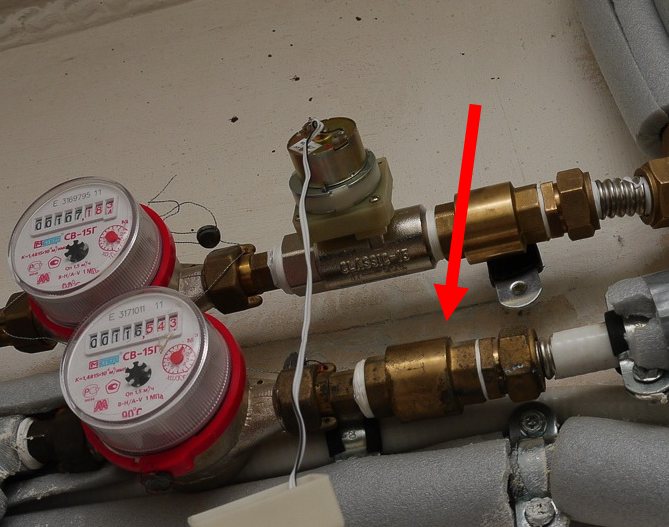
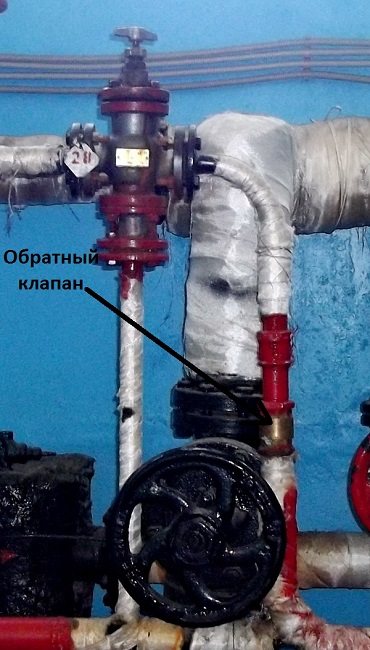
Coupling check valve on the water supply pipeline
In heating systems, protective fittings are installed if the pipeline is equipped with a bypass, which is necessary when installing forced circulation. The valve is mounted between the suction and discharge pipes of the bypass, it prevents the circulation of the coolant in a small circle and directs the liquid to the circulation pump.
How to install a Danfoss coupling valve with your own hands? Initially shut off the water circulation in the system and drain the liquid from the piping. Next, cut the pipe at the place where the fittings will be installed and, using a thread cutter, form a thread for the coupling. Wrap the resulting thread with tow or fumulent (seal layer no more than 1 mm), screw the fittings by hand and tighten with an adjustable wrench. The valve must be screwed onto the pipe at least 5 full turns.
Feedback and valve control
Position indication
Various types of devices can be installed on the valve, showing its position (see Fig. 15), depending on the control system of the entire complex. This includes microswitches, inductive proximity switches, Hall sensors. These switches send feedback signals to the control system.
When only switches are installed on the valves, it is necessary for each valve to have a corresponding solenoid valve in the wall-mounted solenoid valve cabinet. When a signal is received, the solenoid valve directs compressed air to the valve installed in the pipeline, and when the signal is interrupted, the solenoid valve stops the air supply.
In such a system (1), each valve is supplied with an individual electrical cable and its own air hose.
The combination unit (2) is usually mounted on the valve actuator. It includes the same position sensors as the above, and the solenoid valve is installed along with the sensors. This means that one air hose can supply air to several valves, but each valve still needs a separate cable.
Fig. 15 Valve position indication systems. 1 Only sensors 2 Combination unit on the valve actuator 3 Display and control system
Valve body
Depending on the method of body shaping, the valves are forged, cast, welded, stamped or combined: litho-welded (in them, body parts made by casting are connected by welding), stamp-welded (body parts obtained by stamping, forging or rolling are joined by welding), and die-welded.
Angle valves and straight-through valves are distinguished by the type of configuration of the connecting pipes. In angle valves, the axes of the inlet and outlet branch pipes are located perpendicular or at least not parallel to each other. At checkpoints, they are mutually parallel. Passing the angle valve, the flow makes one turn, so the pressure drop in it is less than in a straight-through (straight-through) valve.
The valves can have not only two nozzles ─ inlet and outlet, but also be multi-way. "Multi" is usually three (three-way valve) or four (four-way valve) nozzles.
Like other types of pipeline fittings, valves are available in full bore and partial bore. In the first case, the diameter of the seat is at least 9/10 of the diameter of the opening of the inlet pipe; in the second, the cross-sectional area of the flow path is less than this value.
Full control
It is carried out using a position sensor unit, shown in Fig. 9, which is specially designed for computer control. This unit includes a position indicator, a solenoid valve and an electronic device that can control up to 120 valves with just one cable and one air hose (item 3 in Figure 15). This unit can be centrally programmed and is inexpensive to install.
Some systems may also, without receiving external signals, open valves to flush the seats. They can also count the number of valve strokes.
This information can be used to plan service activities.
Control valves
Shut-off and diverter valves are simple - they or
open, or closed. For a control valve, the orifice diameter can change gradually. This valve is designed to accurately control flow and pressure at various points in the system.
Pressure reducing valve (in Fig. 17) maintains the required pressure in the system. If it drops, the spring presses the valve against the seat. As soon as the pressure rises to a certain level, the pressure on the valve plug overpowers the spring and the valve opens. By adjusting the spring tension, the valve can be opened at a certain hydraulic pressure.
Manual control valve (fig. 18) has a special shaped plug stem.
Turning the adjusting knob moves the valve up or down, decreasing or increasing the passage and therefore the flow rate or pressure. The valve has a graduated scale.
Fig. 19 Valve with pneumatic flow control.
Fig. 20 Constant pressure valve.
Fig. 21 Principle of operation of a constant pressure valve when regulating the pressure upstream of the valve. 1 Equilibrium between air and product 2 Product pressure decreases, the valve closes and the product pressure rises again, rising to the set level 3 Product pressure rises, the valve opens, and the product pressure drops to the set level
Fig. 22 Constant pressure valve with booster pump to regulate product pressure that exceeds the actual compressed air pressure
Pneumatic control valve (fig. 19) functions in the same way as described above. The valve-seat assembly is also similar to a manual valve. As the valve is lowered towards the seat, the flow path gradually narrows.
This type of valve is designed to automatically regulate pressure, flow and level during the process. A sensor is built into the production line that continuously reports the values of the measured parameter to the control device, which makes the necessary adjustments to the gate position in order to maintain the set value.
Constant pressure valve - one of the most commonly used (fig. 20). The compressed air is fed through a pressure reducing valve into the space above the diaphragm.The air pressure is changed by the pressure reducing valve until the product pressure gauge shows the required value. The target product pressure is then kept constant regardless of changes in operating conditions. The principle of operation of a constant pressure valve is shown in figure 21.
The valve responds instantly to changes in product pressure. Decreased product pressure results in an increased force on the diaphragm on the air pressure side, which
remains constant. The valve plug then moves downward with the diaphragm, the flow is limited and the product pressure is increased to a predetermined level.
The increased pressure of the product causes the effect it exerts on the diaphragm to exceed the pressure of the compressed air from the top. In this case, the shutter is pushed upward, increasing the diameter of the channel through which the product passes. The flow rate will increase until the product pressure drops to a predetermined level.
This valve is available in two versions - to maintain a constant pressure upstream or downstream of the valve. The valve cannot regulate the product pressure if the available air pressure is lower than the required product pressure. In such cases, a booster pump can be installed above the valve, and the valve can then operate at product pressures of double the actual compressed air pressure.
Valves providing constant upstream pressure are often installed after separators and pasteurizers. And those that maintain a constant outlet pressure are used in the lines in front of the packaging machines.
Features of choice
The main parameters that you should pay attention to when choosing a check valve (including a flanged one) are:
- working pressure at which such a device can operate;
- nominal bore diameter.
You can find out what operating pressure the check valve corresponds to by the device labeling, in which this parameter is denoted by the letters RU. The numbers in the marking after such letters indicate the operating pressure for which the device is intended. For example, the designation RU16 indicates that a flanged valve can operate at 16 bar without being exposed to excessive wear.
Check valve marking
The nominal diameter, on which it depends on which pipeline a flange-type valve can be installed, is designated by the letters ДУ. Accordingly, the numbers following in the marking after these letters indicate the value of the nominal diameter of the check valve in millimeters. When choosing a check valve for this parameter, keep in mind that such a product can only be mounted on pipeline elements that have the same dimensions. In other words, the DU80 model, for example, can be installed only on pipes or other elements of the pipeline system, the bore diameter of which corresponds to a value of 80 mm.
Valve systems
To minimize the number of dead ends and to be able to distribute the product between different parts of the dairy, the valves are grouped into blocks. Valves also isolate individual lines so that one line can be flushed while other lines are circulating product.
There must always be an open drainage hole between the product streams and cleaning solutions, as well as between the streams of different products.
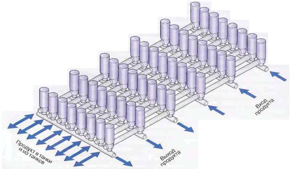
Fig. 23 Valve comb serving tanks. The valves on the tank platform are located in such a way that the flows of product and cleaning solutions entering and leaving the tanks do not intersect
Pipe brackets
The pipelines are laid two to three meters above the floor of the dairy. All units and parts of the pipeline must be easily accessible for inspection and maintenance. Piping should be slightly sloped (1: 200-1: 1000) to ensure self-draining.There should be no "bags" along the entire length of the pipelines so that product or cleaning solution does not accumulate there.
The pipes must be securely fastened. On the other hand, the fastening of the pipes should not be too rigid to exclude any displacement. At high temperatures of the product or cleaning solution, the pipes undergo significant expansion. The resulting elongation and torsional loads in bends and in the equipment must be compensated in a certain way. This circumstance, as well as the fact that various assemblies and details make the pipeline system heavier to a large extent, require high accuracy of calculations and high professionalism from the designers.
Fig. 24 Example of standard pipe supports.