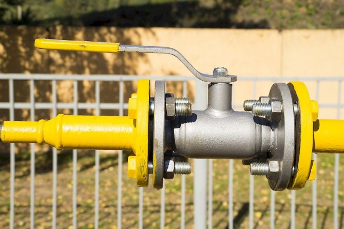
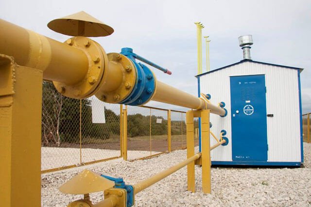
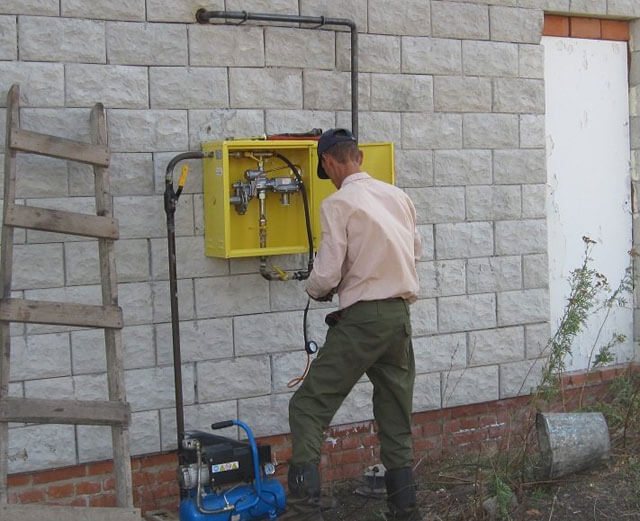
Recommendations for the selection of gas pipes
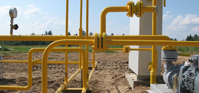
Most often, gas pipelines for honest houses and apartments are equipped with metal products. Steel pipes for gas supply are characterized by the ability to perfectly withstand internal pressure. Such a pipeline is completely sealed, which reduces the risk of gas leakage to zero. When choosing steel pipes for gas pipelines, it is necessary to take into account the pressure in the gas pipeline.
Conditions in gas pipelines can be as follows:
- With low pressure - up to 0.05 kgf / cm2.
- With an average pressure - from 0.05 to 3.0 kgf / cm2.
- With high pressure - from 3 to 6 kgf / cm2.
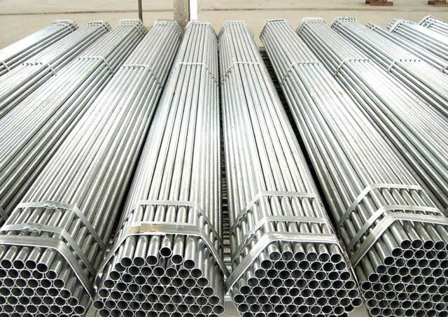
What pipes are used for the gas pipeline? The use of thin-walled metal pipes is only permitted on low pressure gas pipelines. This material is extremely lightweight, which makes it possible to equip systems with complex configurations from it. Also, thin-walled metal pipes are distinguished by good flexibility: if it is necessary to give such a product a small angle, you can do without a pipe bender, having done everything by hand.
If necessary, such a pipe for a gas pipeline is easily soldered. In addition, special connecting fittings can be used for threaded steel pipes. For connection of thin-walled bell-shaped elements, only hemp sealing fiber is used.
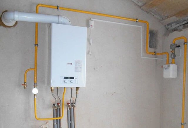
Features of different types of gas boilers
The choice of gas hot water boilers in terms of power is based on design calculations of heat consumption. When reconstructing Moscow city apartments (transferring to autonomous heating), it is rational to install suspended wall-mounted gas heat generators. This installation is due to a shortage of useful living space. In suburban cottages and mansions near Moscow, floor-standing water heating equipment is more often installed. Often, customers arrange a separate boiler room in an extension to a house or in an outbuilding.
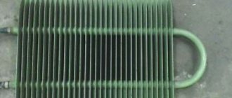
When choosing a single-circuit hot water boiler, gas heating does not provide for hot water supply. Double-circuit gas heating boilers provide heating of the house and supply the residents of the house with hot water for domestic and household needs. When choosing a boiler for gas heating, the material of the heat exchanger (copper is preferred) and the design of the combustion chamber become important criteria. Condensing gas boilers with a recuperator are distinguished by good economic characteristics.
Features of using different types of gas pipes
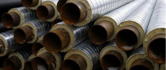
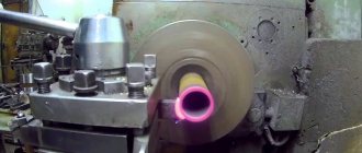
High pressure gas pipelines are equipped exclusively with massive pipes. If increased strength requirements are imposed on the line, the use of steel pipes without seams will be required. You should be prepared for the fact that welding such elements is a much more complicated procedure than brazing thin-walled pipes. From the point of view of optimal performance, copper pipes stand out: in many respects, they are preferable to thick-walled steel products. In terms of reliability, both of these varieties are almost the same, but copper weighs much less. Their high cost keeps copper pipes from mass use in everyday life.
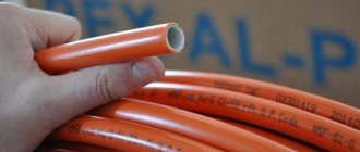
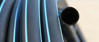
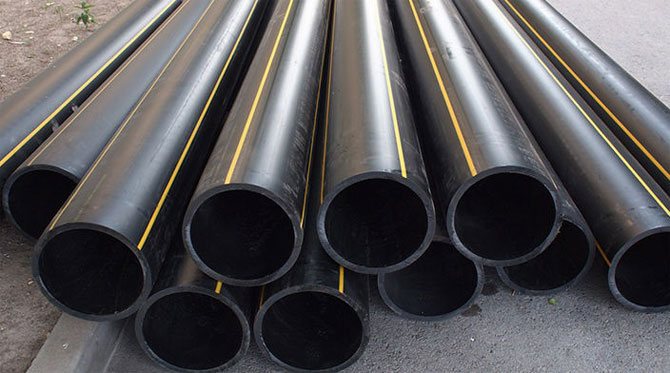
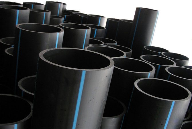
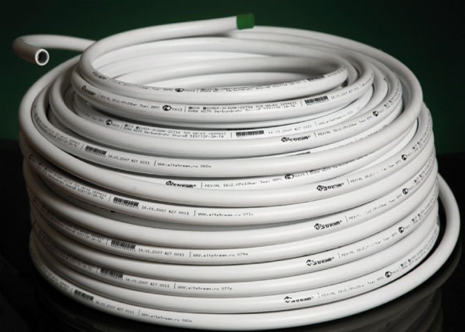
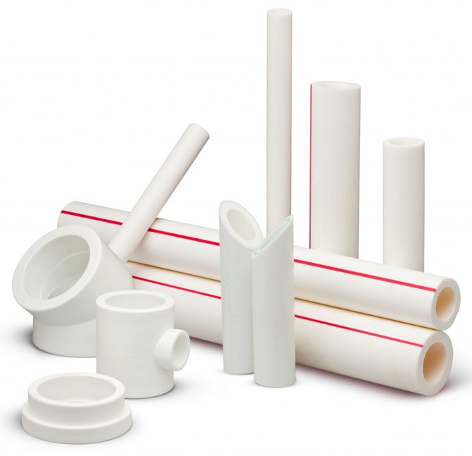
When using thin-walled pipes, one should take into account their high thermal conductivity, which is why condensation often occurs on their surface. It is recommended to coat the finished gas system with several coats of oil paint to protect against corrosion. Underground gas pipelines are organized using plastic pipes, which are characterized by flexibility, elasticity and low cost. Most often these are products made of polypropylene or polyethylene.For example, polyethylene pipes for gas perfectly tolerate underground conditions when gasifying private properties. If it is required to equip the summer cottage with a low-pressure gas pipeline, black polyethylene pipes with the corresponding yellow marking are used. High pressure polyethylene pipes are not used as a gas pipeline.
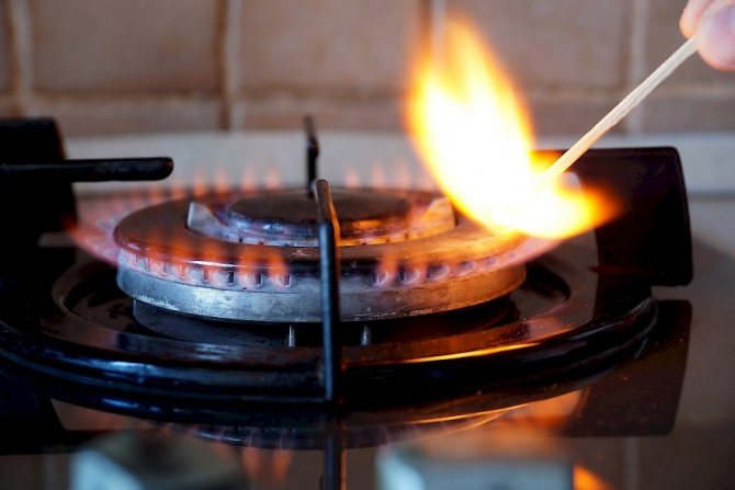
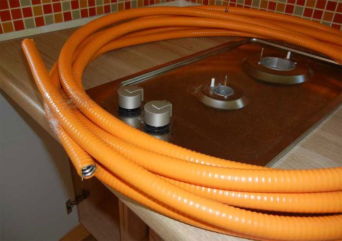
Indoor gas distribution is carried out with vulcanized rubber hoses with textile reinforcement. They are not suitable for high pressure: they are usually used to connect gas stoves to cylinders or gas water heaters.
The use of flexible hoses has the following limitations:
- If the air temperature in the area exceeds +45 degrees.
- If seismic activity of more than 6 points is possible on the territory.
- At high pressure inside the gas pipeline system.
- If you need to equip any room, tunnel or collector with a gas pipeline.
All of these situations are prohibited for using HDPE pipes as a gas pipeline. It will be safer to stop at a thin-walled or seamless type steel gas pipe.
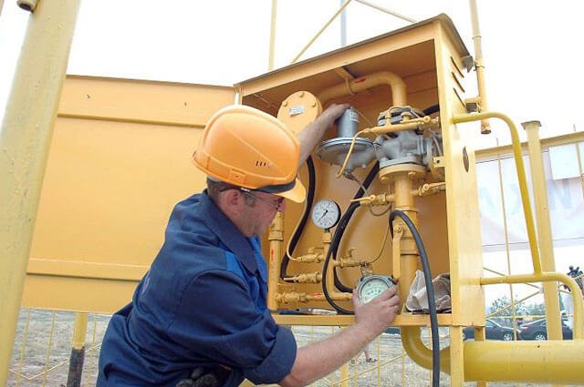
Equipment and tools used for installation
For the installation of the gas pipeline, the foremen use special equipment:
- Long-fiber flax or FUM tape for threaded connections.
- Lever wrenches with parallel jaws. They should be equipped with notches for better adhesion to the part.
- Welding machine.
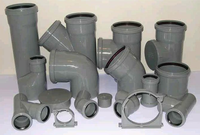
- Fittings - parts with fine threads for connecting several elements.
All tools and system elements must have a certificate from the factory that manufactures these parts. All certificates must comply with the requirements of Gosgortekhnadzor. If there are no certificates, then the use of such pipes is impossible.
Ventilation and safety
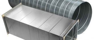
When installing a gas water heater, an exhaust pipe must be used (read: "The nuances of installing exhaust pipes for a gas water heater - expert advice"). It is prohibited to use a flexible corrugated pipe made of aluminum for these purposes. Discharge pipes for the column can only be steel or galvanized. It is recommended to equip a gas column, like any other heating device, with fuses: they will cut off the gas supply in the event of a flame extinguishing.
Features of the arrangement of a gas pipeline in the kitchen from thin-walled metal pipes:
- Work begins by shutting off the gas supply valve.
- If the gas pipe in the kitchen needs to be moved, the gas pipe must be pre-purged to remove the remaining gas from the system.
- The gas pipe on the wall must be very well secured. To do this, the product includes clamps and brackets: they are used taking into account the diameter and length of the pipeline.
- When passing an electric cable near the gas pipeline, a distance of 25 cm should be observed between them.The gas system and the electrical switchboard should be 50 cm apart from each other.
- The gas piped kitchen system should not be adjacent to refrigeration appliances such as a refrigerator or freezer. If you close the gas pipes with a refrigerator, its radiator is likely to overheat.
- When installing thin-walled gas pipes, the heaters and the gas stove should be removed.
- It is forbidden to lay gas pipes in the kitchen on the floor surface, under the sink, near the dishwasher.
- When carrying out repair work, it is advisable not to use artificial light sources. The room must be constantly ventilated.
These standards can be guided by the operation of both ready-made gas systems and the installation or transfer of gas pipelines.
Gasification standards for a private house
Notify the local gas service before starting work. The responsibility of this organization includes the provision of technical specifications to determine the procedure for gasification.When the technical agreement is completed, an individual project is being developed for the upcoming work. Permission for laying gas communications should also be obtained from representatives of the automobile inspection.
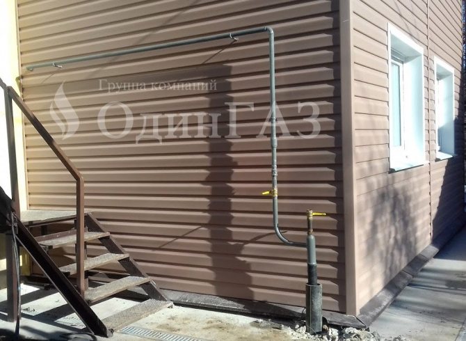
If some houses in this area are already gasified, then you only need to connect a gas pipe to the main highway. In this case, the gas service is obliged to notify about the parameters of the working pressure in the main pipeline. This will make it possible to choose the right pipes for arranging your site. The gas supply system can be autonomous or central: it depends on which source the given section will be supplied from. Private houses can be equipped with aboveground and underground gas pipelines. It is not very difficult to assemble and install gas pipes on the site - it is usually done much faster than obtaining the appropriate permits.
When laying the gas pipeline, the following sequence should be observed:
- Lay the piping from the distributor to the dwelling. If necessary, a tie-in is carried out into the main gas pipeline (for more details: "How is a tie-in into a gas pipe - a step by step guide").
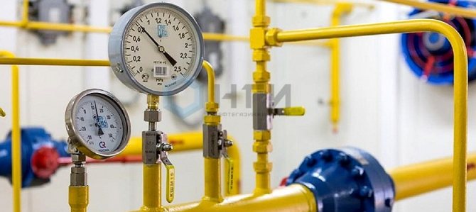
- To enter the pipe inside the house, a cabinet with a pressure reducing reducer is used.
- Next, you need to organize the piping around the premises (kitchen, boiler room). For this, a pipe for a low pressure gas pipeline is used.
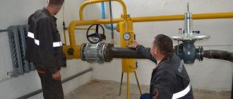
- Carry out commissioning procedures, commissioning of equipment, check the gas stove and the column for operability. Most often, this requires the presence of a gas inspector.
The structure of a gas pipeline in a private house consists of the same points as a similar system in an apartment.
Requirements for the materials used and the installation of the gas network in a private building
Gas installation in a private house and the reliable functioning of the gas network is impossible without observing a number of conditions and norms. We guarantee it 100%.
- All materials used in the construction process, regardless of their further purpose (pipes, valves, electrodes), are of high quality, confirmed by the relevant documents.
- Our masters place collapsible connections in open areas to ensure free access. This makes it possible at any time to assess the state of the connection, to carry out repairs if necessary.
- It is strictly forbidden to embed pipes and other nodes of the gas network into the walls, into the foundation of the structure. In certain cases, permission is given to lay a pipe in a channel specially made in the wall, but only after the approval of the project.
- It is also forbidden to fix the gas pipeline to the frames of windows and doors, transoms and platbands, plywood partitions.
- The presence of distortions when laying local pipelines for supplying gas to premises and to the territory is categorically unacceptable.
- For horizontal sections, an inclination towards the equipment within 0.002-0.005 meters is permissible, and any inclination is excluded in vertical places.
- A slope within 2mm / 1 meter is allowed only on the riser located on the staircase or in the kitchen space.
- Our craftsmen install the cranes by placing the axis of the plug parallel to the wall, on which the thrust nut cannot be.
Maintaining the required distances is a very important safety factor.
- The minimum distance from the pipe to the floor can be 2.2 meters, to the ceiling - from 10 cm.
- The distance between the wall and the pipe is usually specified in the design documentation.
- Its minimum value is equal to the radius of the pipe, and the maximum is 10 cm.
For the construction of a local gas pipeline, we use pipes made of low-carbon or low-alloy steel with a diameter of 150 mm and a wall thickness of 5 mm.We use both welded and seamless products, which are connected to each other only by gas welding using high-quality electrodes.
We recommend installing not only the main, but also a control gas meter when connected to the mains, at least one meter for autonomous gasification. During operation, you can not only monitor the real gas consumption, but also look for options to save fuel.
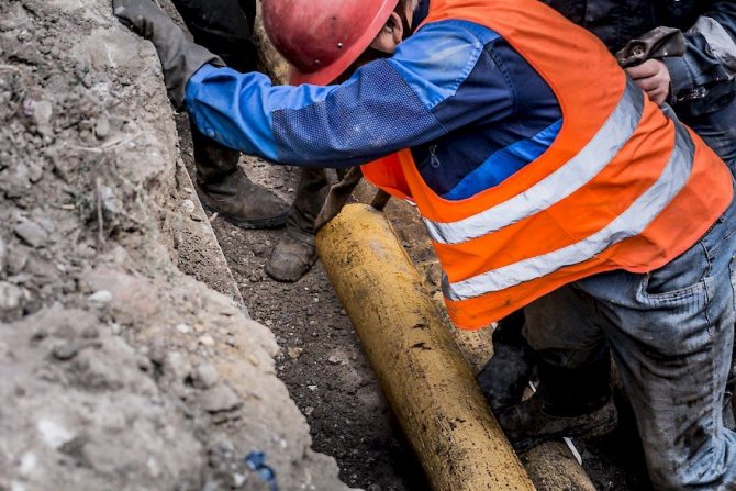
Sequence and installation rules
Installation work should be carried out according to the following rules:
- When laying gas pipes underground, the optimum depth is 1.25 - 2 m.
- At the section where the pipe is inserted into the house, the depth should be reduced to 0.75 - 1.25 m.
- Liquefied gas can be transported at a depth below the depth of soil freezing.
- When installing a gas boiler, it should be borne in mind that one piece of equipment must have a room area of 7.5 m2.
- To install boilers and dispensers with a capacity of less than 60 kW, rooms of at least 2.4 m will be required.
An autonomous gas source in the backyard area is carried out in accordance with specific safety standards. This will ensure the normal functioning of the stove, column and boiler. The underground reservoir should be located no closer than 15 m from the well, 7 m from the outbuildings, and 10 m from the house. The most popular types of such tanks are 2.7 - 6.4 m3.
Rules for laying underground gas pipelines:
- What pipes are used for a gas pipeline in this case? With a positive result of a soil test for corrosiveness, it is better to refrain from laying underground communications. The exception is situations when high-voltage lines pass nearby: in this case, the pipes are carried underground using additional insulation.
- If a polyethylene pipeline is being laid, products with high strength (PE-80, PE-100) are used for this. PE-80 pipes are able to withstand working pressure up to 0.6 MPa: if this figure is higher, it is better to use PE-100 products or steel pipes for high-pressure gas pipeline. The depth of penetration into the ground is at least one meter.
- Communications with a working pressure above about 6 MPa are allowed to be equipped with reinforced polyethylene pipes. Requirements for the depth of the bookmark here are also from one meter.
- In areas where arable work or abundant irrigation will be carried out, the depth of the gas pipeline will increase to 1.2 m.
If you adhere to all the above requirements and rules, you can do the construction of an underground gas pipeline with your own hands.
SNiP 42-01-2002: External gas pipelines
Scope Normative references Terms and definitions General requirements for gas distribution systems
5.1.1 The placement of external gas pipelines in relation to buildings, structures and parallel adjacent engineering networks should be carried out in accordance with the requirements of SNiP 2.07.01, and on the territory of industrial enterprises - SNiP II-89.
When laying underground gas pipelines with a pressure of up to 0.6 MPa in cramped conditions (when the distances regulated by regulatory documents are not possible to fulfill), on certain sections of the route, between buildings and gifts of buildings, as well as gas pipelines with a pressure of over 0.6 MPa when they are brought together with detached ancillary buildings (buildings without the constant presence of people), it is allowed to reduce the distances specified in SNiP 2.07.01 and SNiP II-89 by up to 50%. At the same time, in the areas of convergence and at a distance of at least 5 m in each direction from these areas, the following should be applied:
seamless or electrically welded steel pipes, laid in a protective case, with 100% physical control of factory welded joints;
polyethylene pipes laid in a protective case, without welded joints or connected by parts with embedded heaters (ZN), or butt-welded with 100% control of joints by physical methods.
When laying gas pipelines at distances corresponding to SNiP 2.07.01, but less than 50 m from public railways in the area of convergence and 5 m in each direction, the depth of laying must be at least 2.0 m.Butt welded joints must pass 100% - control by physical methods.
In this case, the wall thickness of steel pipes should be 2-3 mm more than the calculated one, and polyethylene pipes should have a safety factor of at least 2.8.
5.1.2 Laying of gas pipelines should be provided for underground and surface.
In justified cases, above-ground laying of gas pipelines is allowed along the walls of buildings inside residential yards and quarters, as well as on certain sections of the route, including at sections of crossings through artificial and natural barriers when crossing underground utilities.
Aboveground and aboveground gas pipelines with embankment can be laid in rocky, permafrost soils, in swampy areas and under other difficult soil conditions. The material and dimensions of the embankment should be taken on the basis of the heat engineering calculation, as well as ensuring the stability of the gas pipeline and the embankment.
5.1.3 Laying gas pipelines in tunnels, collectors and channels is not allowed. An exception is the laying of steel gas pipelines with a pressure of up to 0.6 MPa in accordance with the requirements of SNiP II-89 on the territory of industrial enterprises, as well as in channels in permafrost soils under roads and railways.
5.1.4 Pipe connections should be provided as one-piece. Connections of steel pipes with polyethylene and
in places of installation of fittings, equipment and instrumentation (instrumentation). Detachable joints of polyethylene pipes with steel pipes in the ground can only be provided if a case with a control tube is installed.
5.1.5 Gas pipelines at the points of entry and exit from the ground, as well as gas pipelines inlets to buildings should be enclosed in a case. The space between the wall and the case should be filled up to the full thickness of the structure to be crossed. The ends of the case should be sealed with elastic material.
5.1.6 Entries of gas pipelines into buildings should be provided directly to the room where the gas-using equipment is installed, or to an adjacent room connected by an open opening.
Gas pipelines are not allowed to enter the premises of the basement and basement floors of buildings, except for natural gas pipelines in single-family and blocked houses.
5.1.7 Disconnecting devices on gas pipelines should include:
in front of detached or blocked buildings;
to disconnect risers of residential buildings above five floors;
in front of outdoor gas-using equipment;
in front of gas control points, except for hydraulic fracturing of enterprises, on the branch of the gas pipeline to which there is a disconnecting device at a distance of less than 100 m from the hydraulic fracturing;
at the exit from gas control points looped by gas pipelines;
on branches from gas pipelines to settlements, separate microdistricts, quarters, groups of residential buildings, and if the number of apartments is more than 400, to a separate house, as well as on branches to production consumers and boiler houses;
when crossing water barriers with two or more lines, as well as one line with a water barrier width with a low-water horizon of 75 m or more;
at the intersection of railways of the general network and highways of categories I-II, if the disconnecting device that ensures the cessation of gas supply at the crossing section is located at a distance of more than 1000 m from the roads
5.1.8 Disconnecting devices on overground gas pipelines laid along the walls of buildings and on supports should be placed at a distance (within a radius) from door and opening window openings at least:
for low pressure gas pipelines - 0.5 m;
for gas pipelines of medium pressure - 1 m;
for high-pressure gas pipelines of the II category - 3 m;
for high-pressure gas pipelines of category I - 5 m.
Installation of disconnecting devices on the sections of transit laying of gas pipelines along the walls of buildings is not allowed.
5.2.1 Laying of gas pipelines should be carried out at a depth of at least 0.8 m to the top of the gas pipeline or case. In places where the movement of vehicles and agricultural machinery is not foreseen, the depth of laying steel gas pipelines can be at least 0.6 m.
5.2.2 The vertical distance (in the light) between the gas pipeline (case) and underground utilities and structures at their intersections should be taken taking into account the requirements of the relevant regulatory documents, but not less than 0.2 m.
5.2.3 At the intersection of gas pipelines with underground communication collectors and channels for various purposes, as well as at the places where gas pipelines pass through the walls of gas wells, the gas pipeline should be laid in a case.
The ends of the case should be brought out at a distance of at least 2 m in both directions from the outer walls of the structures and utilities to be crossed, when crossing the walls of gas wells - at a distance of at least 2 cm. The ends of the case should be sealed with waterproofing material.
At one end of the case, at the upper point of the slope (except for the intersection of the walls of the wells), a control tube should be provided that goes under the protective device.
In the annular space of the case and the gas pipeline, it is allowed to lay a service cable (communication, telemechanics and electrical protection) with a voltage of up to 60 V, intended for servicing gas distribution systems.
5.2.4 Polyethylene pipes used for the construction of gas pipelines must have a safety factor of at least 2.5 in accordance with GOST R 50838.
Laying of gas pipelines from polyethylene pipes is not allowed:
on the territory of settlements at a pressure of over 0.3 MPa;
outside the territory of settlements at a pressure of over 0.6 MPa;
for transportation of gases containing aromatic and chlorinated hydrocarbons, as well as the liquid phase of LPG;
at a gas pipeline wall temperature under operating conditions below minus 15 ° C.
When using pipes with a safety factor of at least 2.8, it is allowed to lay polyethylene gas pipelines with a pressure of more than 0.3 to 0.6 MPa in the territories of settlements with mainly one-two-story and cottage residential buildings. On the territory of small rural settlements, it is allowed to lay polyethylene gas pipelines with a pressure of up to 0.6 MPa with a safety factor of at least 2.5. In this case, the laying depth must be at least 0.8 m to the top of the pipe.
5.3.1 Aboveground gas pipelines, depending on pressure, should be laid on supports made of non-combustible materials or along structures of buildings and structures in accordance with Table 3
Table 3
| Placement of aboveground gas pipelines | Gas pressure in the gas pipeline, MPa, not more |
| 1. On freestanding supports, columns, overpasses and deck houses | 1.2 (for natural gas); 1.6 (for LPG) |
| 2. Boiler houses, industrial buildings with rooms of categories B, D and D and buildings of the GNS (GNP), public and domestic buildings for industrial purposes, as well as built-in, attached and roof boiler houses to them: | |
| a) on the walls and roofs of buildings of I and II degrees of fire resistance of fire hazard class CO (SNiP 21-01) | 1,2* |
| II degree of fire resistance class C1 and III degree of fire resistance class CO | 0,6* |
| b) on the walls of buildings of III degree of fire resistance of class C1, IV degree of fire resistance of class CO | 0,3* |
| IV degree of fire resistance of classes C1 and C2 | 0,005 |
| 3. Residential, administrative, public and service buildings, as well as built-in, attached and roof boiler rooms | |
| on the walls of buildings of all degrees of fire resistance | 0,005 |
| in cases where ShRP is placed on the outer walls of buildings (only ShRP) | 0,3 |
| * The gas pressure in the gas pipeline laid in the building structure must not exceed the values indicated in Table 2 for the respective consumers. |
5.3.2 Transit laying of gas pipelines of all pressures along the walls and over the roofs of buildings of children's institutions, hospitals, schools, sanatoriums, public, administrative and residential buildings with a mass presence of people is not allowed.
It is prohibited to lay gas pipelines of all pressures along the walls, above and below rooms of categories A and B, determined by fire safety standards [1], with the exception of hydraulic fracturing buildings.
In justified cases, transit laying of gas pipelines not higher than average pressure with a diameter of up to 100 mm is allowed along the walls of one residential building not lower than III degree of fire resistance of class CO and at a distance of at least 0.2 m from the roof.
5.3.3 High-pressure gas pipelines should be laid along blank walls and sections of walls or at least 0.5 m above window and door openings of the upper floors of industrial buildings and administrative and household buildings interlocked with them. The distance from the gas pipeline to the roof of the building must be at least 0.2 m.
Low and medium pressure gas pipelines can also be laid along the bindings or imposts of non-opening windows and cross the window openings of industrial buildings and boiler rooms filled with glass blocks.
5.3.4 The height of the laying of aboveground gas pipelines should be taken in accordance with the requirements of SNiP 11-89.
5.3.5 On pedestrian and road bridges built of non-combustible materials, it is allowed to lay gas pipelines with a pressure of up to 0.6 MPa from seamless or electric-welded pipes that have passed 100% inspection of factory welded joints by physical methods. The laying of gas pipelines on pedestrian and road bridges built of combustible materials is not allowed.
5.4.1 Underwater and surface gas pipelines in places where they cross water barriers should be located at a distance from bridges horizontally in accordance with Table 4.
5.4.2 Gas pipelines at underwater crossings should be laid with deepening into the bottom of the crossed water barriers. If necessary, according to the results of calculations for ascent, it is necessary to ballast the pipeline. The elevation of the top of the gas pipeline (ballast, lining) should be at least 0.5 m, and at crossings through navigable and floatable rivers - 1.0 m lower than the predicted bottom profile for a period of 25 years. When performing works using the directional drilling method - not less than 2.0 m below the predicted bottom profile.
5.4.3 On underwater crossings the following should be applied:
steel pipes with a wall thickness of 2 mm more than the calculated one, but not less than 5 mm;
polyethylene pipes having a standard dimensional ratio of the outer diameter of the pipe to the wall thickness (SDR) no more than 11 (according to GOST R 50838) with a safety factor of at least 2.5 for transitions up to 25 m wide (at the level of maximum water rise) and at least 2.8 otherwise.
When laying a gas pipeline with a pressure of up to 0.6 MPa by directional drilling, in all cases, polyethylene pipes with a safety factor of at least 2.5 can be used.
5.4.4 The height of the gas pipeline surface crossing from the design level of water rise or ice drift according to SNiP 2.01.14 (high water horizon - GWV or ice drift - GVL) to the bottom of the pipe or superstructure should be taken:
at the intersection of ravines and beams - not lower
Table 4
| Water barriers | Bridge type | Horizontal distance between the gas pipeline and the bridge, not less, m, when laying the gas pipeline | |||||
| above the bridge | below the bridge | ||||||
| from the surface gas pipeline with a diameter, mm | from an underwater gas pipeline with a diameter, mm | from the surface gas pipeline | from the underwater gas pipeline | ||||
| 300 or less | over 300 | 300 or less | over 300 | all diameters | |||
| Shipping freezing | All types | 75 | 125 | 75 | 125 | 50 | 50 |
| Shipping non-freezing | Also | 50 | 50 | 50 | 50 | 50 | 50 |
| Non-navigable freezing | Multi-span | 75 | 125 | 75 | 125 | 50 | 50 |
| Non-navigation non-freezing | ” | 20 | 20 | 20 | 20 | 20 | 20 |
| Non-navigable for gas pipelines pressure: low, medium and high | One- and two-span | 2 5 | 2 5 | 20 20 | 20 20 | 2 5 | 10 20 |
| NOTE Distances are from bridge protruding structures. |
0.5 m above the hot water supply with 5% coverage;
when crossing non-navigable and non-floating rivers - at least 0.2 m above the GWV and GVL of 2% supply, and if there is a grubber on the rivers - taking it into account, but not less than 1 m above the GWV of 1% supply;
when crossing navigable and floating rivers - not less than the values established by the design standards for bridge crossings on navigable rivers.
Stop valves should be placed at a distance of at least 10 m from the boundaries of the transition. The places where the gas pipeline crosses the high water horizon with 10% coverage are taken as the border of the crossing.
5.5.1 Distances horizontally from the intersection of underground gas pipelines of tram and railway tracks and highways must be at least:
to bridges and tunnels on public railways, tramways, highways of categories I – III, as well as to pedestrian bridges, tunnels through them - 30 m, and for non-public railways, highways of IV – V categories and pipes - 15 m ;
to the turnout zone (the beginning of the wits, the tail of the crosspieces, the points of connection to the rails of the suction cables and other crossings) - 4 m for tram tracks and 20 m for the railways;
to the overhead supports - 3m.
It is allowed to reduce the specified distances in agreement with the organizations in charge of the crossed structures.
5.5.2 Underground gas pipelines of all pressures at intersections with railway and tram tracks, highways of categories I-IV, as well as main streets of city-wide importance should be laid in cases. In other cases, the question of the need for the device of the cases is decided by the design organization.
Cases must meet the conditions of strength and durability. A test tube should be provided at one end of the case, which extends under the protective device.
5.5.3 The ends of the cases when crossing gas pipelines of public railways should be removed at a distance from them not less than the established SNiP 32-01. When laying inter-settlement gas pipelines in cramped conditions and gas pipelines on the territory of settlements, it is allowed to reduce this distance to 10 m, provided that an exhaust plug with a sampling device is installed at one end of the case, brought out at a distance of at least 50 m from the edge of the roadbed (the axis of the outer rail at zero marks).
In other cases, the ends of the cases should be spaced at a distance:
not less than 2 m from the extreme rail of the tramway and 750 mm gauge railways, as well as from the edge of the carriageway of streets;
not less than 3 m from the edge of the drainage structure of roads (ditch, ditch, reserve) and from the extreme rail of non-public railways, but not less than 2 m from the foot of the embankments.
5.5.4 When gas pipelines cross public railway lines of 1520 mm gauge, the gas pipeline laying depth must comply with SNiP 32-01.
In other cases, the depth of laying the gas pipeline from the foot of the rail or the top of the road surface, and in the presence of an embankment, from its bottom to the top of the case, must meet safety requirements, but not less than:
when performing work by an open method –1.0 m;
when performing works by punching shear or directional drilling and shield penetration –1.5 m;
when performing work by the puncture method - 2.5m.
5.5.5 The wall thickness of the pipes of a steel gas pipeline when it crosses public railways should be 2–3 mm more than the calculated one, but not less than 5 mm at distances of 50 m in each direction from the edge of the roadbed (the axes of the outer rail at zero marks) ...
For polyethylene gas pipelines in these sections and at the intersections of categories I – III highways, polyethylene pipes of no more than SDR 11 with a safety factor of at least 2.8 should be used.
5.6.1 Gas supply to cities with a population of over 1 million people. with seismicity of the terrain more than 6 points, as well as cities with a population of more than 100 thousand people. if the seismicity of the terrain is more than 7 points, it should be provided from two or more sources - main gas distribution stations with their placement on opposite sides of the city. At the same time, high and medium pressure gas pipelines should be designed as looped-through with their separation into sections by disconnecting devices.
5.6.2 Crossings of gas pipelines through rivers, ravines and railway tracks in excavations, laid in areas with seismicity more than 7 points, should be provided for aboveground. The structures of the supports should provide the ability to move gas pipelines that occur during an earthquake.
5.6.3 During the construction of underground gas pipelines in seismic areas, in undermined and karst areas, at the intersection with other underground utilities, at the corners of gas pipelines with a bend radius of less than 5 diameters, at the branching points of the network, the transition from underground to aboveground, the location of permanent connections "Polyethylene-steel", as well as within settlements on linear sections 50 m apart, control tubes should be installed.
5.6.4 The depth of laying gas pipelines in soils of an unequal degree of heaving, as well as in bulk soils, should be taken to the top of the pipe - not less than 0.9 of the standard freezing depth, but not less than 1.0 m.
With uniform heaving pounds, the depth of the gas pipeline to the top of the pipe should be:
not less than 0.7 standard freezing depth, but not less than 0.9 m for medium-porous soils;
not less than 0.8 of the standard freezing depth, but not less than 1.0 m for strongly and excessively heaving soils.
5.6.5 For LPG tank installations with underground reservoirs in heaving (except for slightly heaving), medium and strongly swelling soils, an overground laying of liquid and vapor gas pipelines connecting the reservoirs shall be provided.
5.6.6 If the seismicity of the area is more than 7 points, in undermined and karst areas, in areas of permafrost, for polyethylene gas pipelines, pipes with a safety factor of at least 2.8 should be used. Butt welded joints must be 100% tested by physical methods.
5.7.1 For restoration (reconstruction) of worn-out underground steel gas pipelines outside and on the territory of urban and rural settlements, the following should be used:
at a pressure of up to 0.3 MPa inclusively, pulling polyethylene pipes in a gas pipeline with a safety factor of at least 2.5 without welded joints or connected using parts with ZN, or butt-welded using welding equipment of a high degree of automation;
at a pressure of 0.3 to 0.6 MPa, inclusive, pulling polyethylene pipes in a gas pipeline without welded joints or connected using parts with ZN or butt welding using welding equipment of a high degree of automation with a safety factor for gas pipelines in the territory of settlements of at least 2, 8, and outside settlements - not less than 2.5. The space between the polyethylene pipe and the steel worn out gas pipeline (frame) along the entire length must be filled with a sealing (sealing) material (cement-sand mortar, foam material);
at a pressure of up to 1.2 MPa, lining (using the Phoenix technology) of the cleaned inner surface of gas pipelines with a synthetic fabric hose on a special two-component glue, subject to confirmation in the established order of their suitability for these purposes at the specified pressure or in accordance with the standards (technical conditions) ; the scope of which applies to this pressure.
5.7.2 The restoration of worn-out steel gas pipelines is carried out without changing the pressure, with an increase or decrease in pressure in comparison with the existing gas pipeline.
At the same time, it is allowed to save:
intersection of rehabilitated areas with underground utilities without installing additional cases;
the depth of the restored gas pipelines;
the distance from the restored gas pipeline to buildings, structures and utilities according to its actual location, if the pressure of the restored gas pipeline does not change or when the pressure of the restored gas pipeline rises to 0.3 MPa.
The restoration of worn-out steel gas pipelines with an increase in pressure to high is allowed if the distances to buildings, structures and utilities meet the requirements for a high-pressure gas pipeline.
5.7.3 The ratio of the sizes of polyethylene and steel pipes during reconstruction by the pulling method should be selected based on the possibility of free passage of polyethylene pipes and parts inside steel pipes and ensuring the integrity of polyethylene pipes. The ends of the reconstructed sections between the polyethylene and steel pipes must be sealed.
Gas control points and installations Internal gas pipelines Tank and cylinder installations of liquefied hydrocarbon gases Gas filling stations (points) of liquefied hydrocarbon gases (HPS) Construction supervision and acceptance of work performed Appendix A List of regulatory documents referenced in SNiP 42-01-2002 Appendix B Acceptance certificate of the completed construction of the gas distribution system object Appendix B Bibliography