Gas column Proton-1M
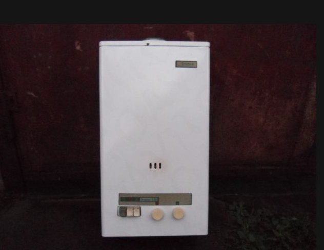
The factory name for these models is VPG - 1712 - V11 - UHL4.2. The appearance of the apparatus is shown in Fig. 1. Dimensions (height X width X depth) are 719X360X230 mm, weight - 13 kg, productivity - 5 liters of hot water per minute. The functional diagram of the gas column is shown in Fig. 2.
Let's take a closer look at the principle of operation of the device.
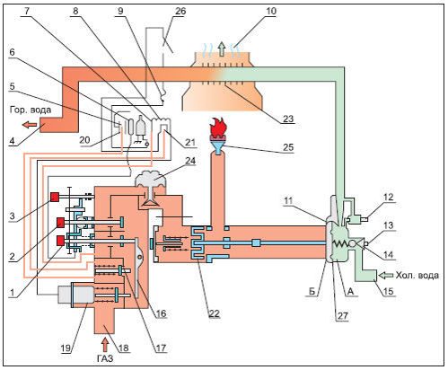
Cold water from a water pipe or a well under a pressure of 2.0 ... 2.5 kg / cm2 from inlet 15 enters the heat exchanger 23. Here the water is heated to a predetermined temperature and through outlet 4 goes into the hot water supply system of the premises. Natural gas from the main through the inlet 18 enters the valve 19. The purpose of the valve 19 is to interrupt the gas supply in the event of an emergency failure in the column or insufficient gas pressure in the inlet main. Having passed the valve, the gas enters the reducer, which reduces the excess pressure, and then through the valve 22 - to the central burner 25. The central burner is ignited by the flame of the pilot burners 7, 20, 21.
When you turn off the device with button 1 and hold it down for 3 seconds. Lever 16 opens valve 19 and valve 17. Gas enters the fast ignition burner 20. Button 1 contains a piezo ignition device connected to spark plug 5. At the moment of pressing button 1, a spark is generated between the central pin of the spark plug and the body, igniting the gas in burners 7, 20, 21. After a short time (2-3 seconds), an emf appears on the thermocouples 6, 8, which keeps the valve 19 open. When button 2 "Open" is pressed, gas flows through the reducer 24 and valve 22 to the main burner 25. In the initial state, the valve is closed and opens if there is a flow of hot water.
The stability of the water temperature at the outlet of the apparatus is ensured by a pressure reducing valve 24 and a valve 14, which maintain constant gas and water pressure, set by a regulator located on the front panel of the apparatus. In the "Proton-1M-1" model, a thermometer is additionally installed for visual control of the water temperature. The device is switched off by pressing button 3 "Extinguishing" mechanically connected with button 1 "Ignition" and button 2 "Opening". After the first click, the main burner turns off. The device switches to standby mode when only the pilot burner is on. Then, upon further pressing, after the second click, the ignition burner is also turned off. To transfer the gas water heater from standby mode to working mode, it is enough to open the tap in the hot water supply system. Consider the operation of the column automation system in various emergency situations.
Proton gas column malfunctions
# 1. Ignition burner has gone out
Possible reasons: short-term interruption of gas supply, blowing out of the flame with a gust of air, thermocouple malfunction. As a result, thermocouple 6 stops heating, the voltage at its outputs decreases to zero. The solenoid valve 19 is turned off by a spring and interrupts the gas supply to the apparatus. The column turns off.
# 2. Lack of draft in the chimney
Possible reasons: chimney clogging, mechanical damage. In this case, the outflow of hot gas through the chimney is sharply reduced. The temperature of the thermostat 26 rises above 900C and the thermostat turns off. As a result, the voltage supply circuit to the valve 19 is broken and the device is turned off.
No. 3. Lack of water in the heat exchanger
A possible cause is a violation of the tightness of the heat exchanger. The temperature of the heat exchanger 23 rises sharply.At temperatures above 1300C fuse 9, located on the thermostat, melts. The voltage supply circuit to valve 19 is broken and the column is turned off.
No. 4. Short-term interruption of gas supply from the main
Possible reasons - repair work on the gas main. As a result, the ignition burner 7 goes out, the thermocouple 6 stops generating emf, and the solenoid valve 19 interrupts the gas supply. When the supply is resumed, the gas will not be able to enter the device, since the valve 19 is closed. To resume work, you must turn on the column again. This is done in the usual way.
No. 5. Interruption of water supply or pressure drop below 25kPa (0.25 kg / cm2)
A decrease in pressure in the city water supply system occurs mainly among consumers living on the upper floors of high-rise buildings during the hours of maximum water intake. For a country house, there are possible reasons: a decrease in the debit (productivity) of a well, a malfunction of a water supply station. To prevent an accident, the device has a device called a "water unit". The device works as follows. When the water is turned off, the pressure in cavities A and B are equalized. Membrane 27 moves to the right and valve 22 cuts off the gas supply to the main burner. The column switches to standby mode.
In order to ensure the reliability of the gas water heater, the elements of the automation circuit are completed with parts produced by well-known foreign companies, for example, the thermostat is manufactured by the English company Elmwood Sensor, and the solenoid valve and thermocouple are manufactured by the Czech company Mora Moravia. To protect against the ingress of foreign objects, filters are installed at the gas and water inlets. The fact that Proton - 1M is the winner of the competition "100 best goods of Russia" also testifies to the reliability and quality of the device.
Gas column "Proton - 3 / 3-1"
The factory name of these models is "VPG-17 12-V11-UHL 4.2". They have a power of 17 kW, overall dimensions 809 X 360 X 250 mm, weight - 15 kg and productivity - 5 liters of hot water per minute. The functional diagram of the apparatus is shown in the figure.
Let's consider the principle of operation of the Proton - 3 / 3-1 apparatus.
To turn on the gas column, press the button 3 of the solenoid valve all the way. While holding down the button 3, the button 1 of the piezoelectric ignition is pressed. Gas from the line passes through valve 5, filter 23 and enters the ignition burner 18. The spark on the spark plug 17 ignites the gas. After that, the button 1 is released. Keep button 3 pressed (for about 30 seconds). During this time, the thermocouple 16 heats up. At its output, an emf appears, which keeps the solenoid valve 6 open. Now button 3 can be omitted. Radiator. Gas will begin to flow to the main burner 19 only after the hot water tap in the system is opened. This will open valves 9, 10 and the burner will light up. The device has a water reducer 13, which allows you to maintain a constant inlet water temperature when the pressure in the water supply changes. The device has a thermometer to control the temperature of hot water. On the front panel of the column there are knobs for adjusting the gas supply to the main burner and the water flow rate. The operation of the automation system in the event of emergency situations (similar to that discussed earlier in the "Proton - 1 M" apparatus).
Disadvantages of the gas column "Proton - 3/3 - 1" in comparison with "Proton - 1M":
- due to the absence of an additional thermocouple, the column turn-on time increased from 3 to 30 sec;
- due to the absence of a gas reducer, the change in gas pressure in the inlet line is not monitored, which leads to an increase in the instability of the hot water temperature;
- insufficient mechanical strength of the solenoid valve activation button.
The advantages of "Proton - 3 / 3-1" include a lower price with a high degree of reliability of the automation circuit.
Overview of Tula speakers
"Proton-1M"
Production designation VPG-1712-V11-UHL4.2. Dimensions - 71.9x36x23 cm (height / width / depth). The device weighs a little - 13.5 kg. Heated water is dispensed at a rate of 5 l / min.
"Proton 2"
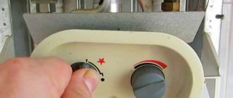
17 kW. 15 kg - weight. The technical characteristics are the same as in the previous version. They differed in their lower cost. The price reduction was achieved by simplifying the design of the gas-water unit. There are no reducers - therefore there is no parameter stability. A thermometer is also not provided. On the facade - a push-button piezo-ignition lever and a mechanical regulator.
The device can operate at low pressure in water pipes - this fact is important for consumers without centralized water supply. The minimum is set with an adjusting screw located directly on the water reducer.
Constructive simplicity and the absence of blockers is a fact that forces users to follow the instructions of the instructions as accurately as possible. It is strictly forbidden to ignite the main burner if the DHW taps are open. This situation causes the accumulation of fuel in the column - if you then turn on the piezo ignition, it can explode.
"Proton 3"
Their power is 17 kW. They weigh 15 kg and heat 5 liters of water every minute. Functional and electrical diagram and protection systems are similar to the previous models. But when compared with the 1M modification, the third model has several disadvantages:
- Holding the push-button lever has increased tenfold - you have to hold it for half a minute.
- There is no gas reducer - it is impossible to track how the pressure in the gas pipeline changes. The result is that it is not possible to stabilize the heating in the hot water supply; it is difficult for the owners of such a column to wash comfortably.
- Pushbutton levers are not strong enough and tend to break.
Plus - a low price with a fairly reliable automatic protection.
Gas columns "Proton-2 / 2-1"
The factory name for these models is "VPG 17 12-V11UHL 4.2". They have a power of 17 kW, overall dimensions 809 X 360 X 250 mm, weight - 15 kg, productivity - 5 liters of hot water per minute.
The functional diagram is shown in the figure.
These are budget models. Compared to the previous devices, they have a simpler design and a gas-water unit of domestic production. Due to the absence of water and gas reducers in the circuit, the temperature of the heated water changes depending on the pressure of water and gas in the supply lines. A hot water thermometer is not provided. On the front panel of the device, there is a piezo ignition button 1 and a gas supply adjustment knob for the main burner. To turn on the gas column, the gas supply adjustment knob is moved from the extreme left position to the ignition sector. The hot water tap in the system must be closed. Press button 1 all the way. Piezo ignition of the pilot burner takes place. The burner flame is clearly visible through the cutout on the front panel. After a short time (about 20 seconds) required for the thermocouple to warm up, the button is released.
I turn on the hot water tap. The central burner then lights up. Set the desired water thermocouple with the gas supply knob. "Proton 2 / 2-1" refers to devices capable of operating at reduced water pressure (from 4 kPa). This is especially important if there is no centralized water supply. The value of the minimum pressure is set using the adjusting screw, which is located on the housing of the water reducer. It should be noted that due to the simplified design of the apparatus and the absence of additional locking devices in the automation circuit, it is necessary to strictly follow the rules for operating the gas column.
It is strictly forbidden to turn on the column in the sector of the main burner when the hot water tap is open! In this case, a large amount of gas from the mainline can accumulate in the device and an explosion is possible when the piezo ignition is turned on.
If you smell gas in the room, turn off the column and close the gas valve installed on the gas pipeline in front of the device. Do not perform actions that could lead to the formation of a spark: do not light a fire, do not turn on electrical appliances and lighting, do not smoke. It is necessary to ventilate the room. This precaution is necessary! A mixture of gas with air forms an explosive mixture that can explode from the slightest spark. The location of the gas leak is determined using a soap solution.
Checking with a lit match is prohibited! The most common cause of malfunctions of the gas columns listed above is a leak in the plug valve at the inlet of the column. Over time, the lubricant inside the tap dries out and the tightness is broken. To eliminate the malfunction, shut off the gas supply from the main line and disassemble the valve. Old grease is removed with kerosene or another solvent.
If there are deep scratches during the repair of the gas water heater, grind the tap cone with fine sandpaper. Then the cone is abundantly lubricated with a thick grease, inserted into the valve body and tightened the nut. For lapping, turn the tap round and round several times. In ball valves, the defect is much less common. Leakage at the pipe joint is eliminated by additional tightening of couplings and nuts.
Repair and service
The main malfunctions of the VPG-23 column include:
1. The main burner does not light up:
- little water pressure;
- deformation or rupture of the membrane - replace the membrane;
- clogged venturi nozzle - clean the nozzle;
- the stock came off the plate - replace the stock with a plate;
- misalignment of the gas part in relation to the water part - align with three screws;
- the stem does not move well in the stuffing box - lubricate the stem and check the nut tightness. If the nut is loosened more than necessary, water may leak from under the stuffing box.
2. When the water intake is stopped, the main burner does not go out:
- dirt has got under the safety valve - clean the seat and valve;
- the cone spring is weakened - replace the spring;
- the stem does not move well in the stuffing box - lubricate the stem and check the nut tightness. If the pilot flame is present, the solenoid valve is not held open:
3. Violation of the electrical circuit between the thermocouple and the electromagnet (open circuit or short circuit). Possible reasons are as follows:
- lack of contact between the terminals of the thermocouple and the electromagnet - clean the terminals with sandpaper;
- violation of the insulation of the copper wire of the thermocouple and its short circuit with the tube - in this case, the thermocouple is replaced;
- violation of the insulation of the turns of the coil of the electromagnet, their closure to each other or to the core - in this case, the valve is replaced;
- disruption of the magnetic circuit between the armature and the core of the electromagnet coil due to oxidation, dirt, grease, etc. It is necessary to clean the surfaces with a piece of coarse cloth. It is not allowed to clean the surfaces with files, sandpaper, etc.
4. Insufficient heating of the thermocouple:
- the working end of the thermocouple is smoked - remove soot from the hot junction of the thermocouple;
- the igniter nozzle is clogged - clean the nozzle;
- the thermocouple is incorrectly positioned relative to the igniter - position the thermocouple relative to the igniter so as to ensure sufficient heating.