The good old oil heater is broken. What to do? Logic suggests: "Take it for repair", and ingenuity: "Look on the Internet and do it yourself!"
Well, right! Repairing oil heaters is not easy, but it may require little maintenance. Therefore, without checking, do not rush to throw away the device and buy a new one!
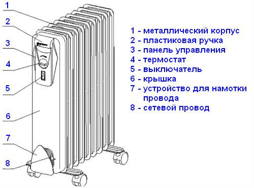
Device device
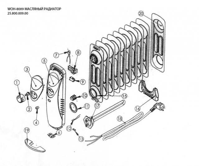
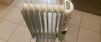
Oil cooler Watt WOH-80
The components of an oil heater are:
- Hermetic body in the form of an accordion, consisting of two panels welded to each other. Technical oil is pumped inside, and in almost all models small amounts of air remain. But this does not harm the device, because oil, when it comes into contact with air, does not create conditions for corrosion. If there was water instead, the probability of rupture of metal structures would be very high.
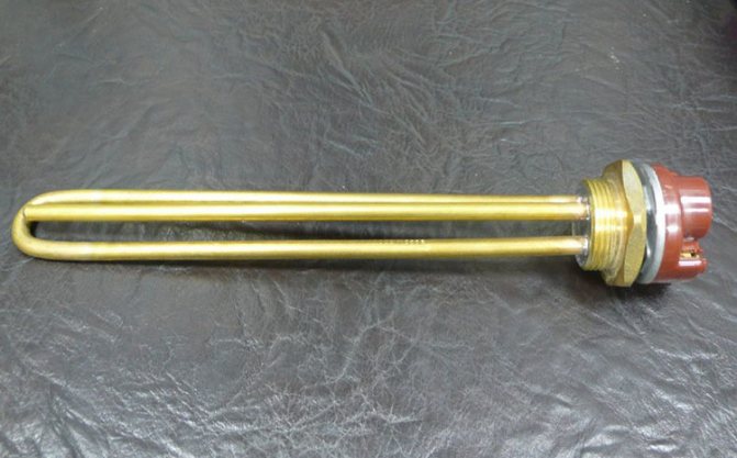
- In the lower part, a heating element is inserted into the device on the side. It is with its help that the oil and the radiator itself are heated.
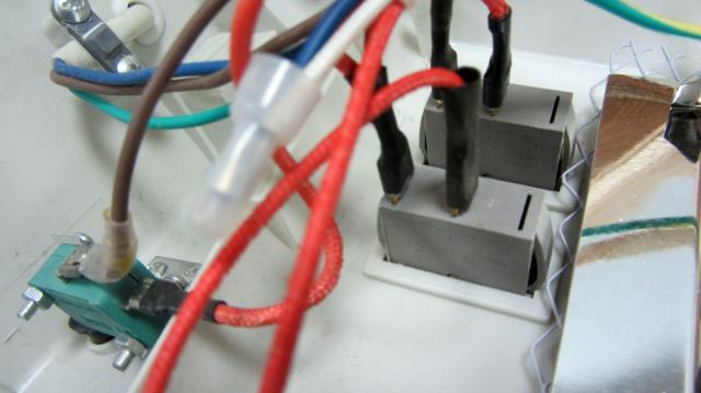
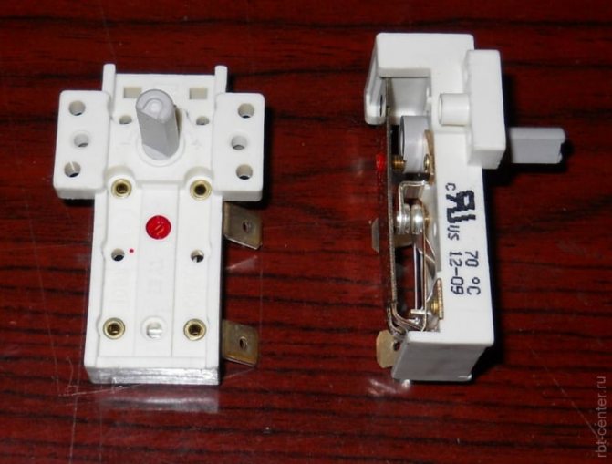
- A control and safety unit is installed next to the heating element. Its main and important element is a thermostat with a fuse. The first is responsible for setting the required temperature regime, and the second is responsible for the safety of operation. If, for any reason, oil begins to flow out of the housing, the fuse will work and stop the supply of electricity to the heating element.
Today manufacturers use disposable wire-type fuses or reusable bimetallic pills. As for the control relays, in oil heaters they are similar to an electric kettle, and not to irons. In the design, the relay hangs in the air without touching the device case.
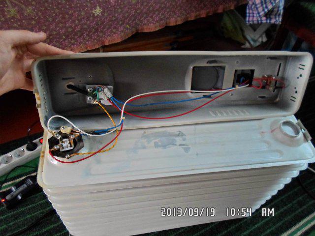
- Each device has two switches. Three wires are suitable for each - a phase, zero from the heating element and a wire from a thermal relay. Three wires are required for the backlighting of the switches to work.
The electrical circuit of an oil heater is practically the same as in irons, electric kettles and other heating devices. It is simple yet reliable. Usually, all these heaters have two heating elements, and when both are turned on at once, the power consumption increases greatly. But at the same time, the time to reach the operating temperature increases. If the temperature in the rooms is low, then even with two heating elements turned on, the device can work without turning off.
The metal case, which covers the power and safety unit of the device, has ventilation slots at the top and bottom. If you close them, the device will not suffer from this, but it will be difficult to work. It will turn off faster, but not turn on so soon. Therefore, it is recommended not to hang items to dry on the radiator. If this happens, try not to cover the ventilation gaps.
Major malfunctions
There are not so many reasons why the oil heater does not work. They can be conditionally divided into two parts - electrical and mechanical. Failure in the operation of electrical equipment most often occurs in the heating element and control communications - thermal relay, switch, thermal fuses. There may be a problem in the wiring, but this is extremely rare.
Mechanical damage includes various holes in the case, as well as the formation of cavities on it through which oil flows out. As a rule, these are the fruits of corrosion activity. Determining the type of malfunction is not difficult. Mechanical breakdowns are always associated with oil stains under the heater.All other faults are related to the electrical part.
We repair the heater
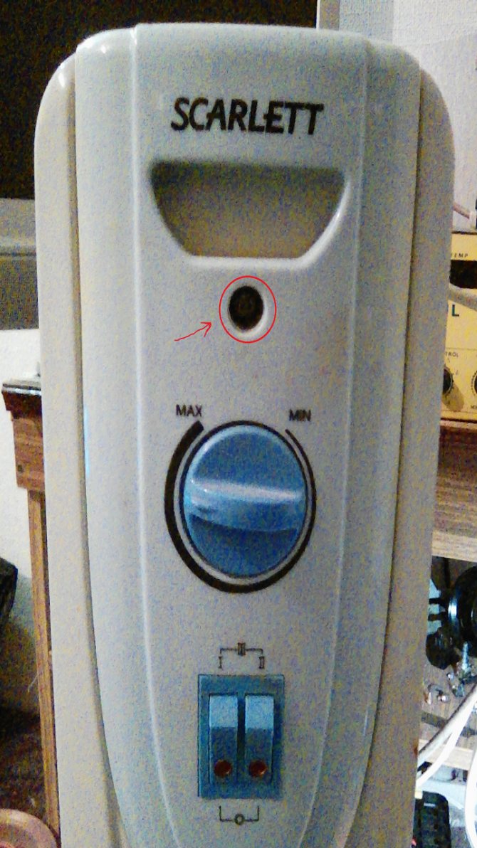
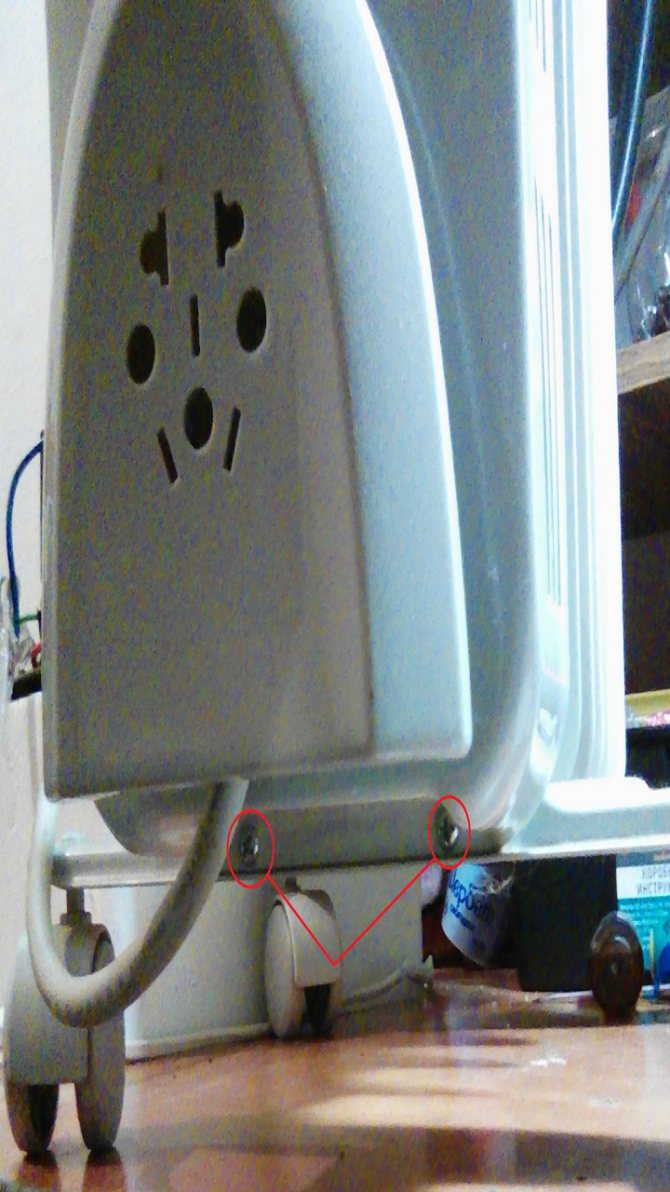
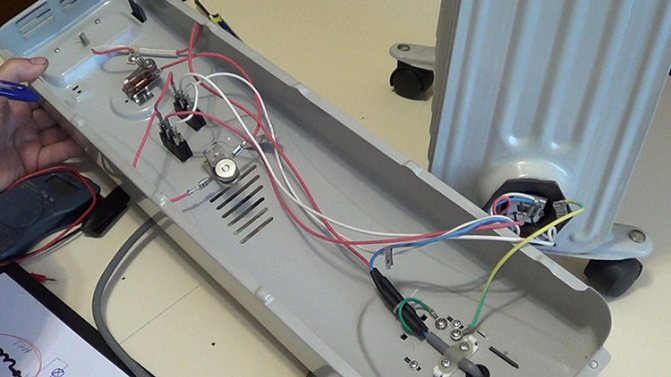
The appearance of the heater gives the impression that it is a single whole, that is, the electric unit and the body are connected by means of a rolling. But this is only an appearance. Pay attention to the inscription "do not cover" - there are several screws under it, with which the cover is held on the case. They need to be unscrewed, but the lid will not come off, because a spring is installed at its bottom that holds it. Just remove it and remove the cover.
Now pay attention to the heating element. It is sealed tightly and hermetically. The manufacturers did this on purpose so that the curious would not go in there. These tubular heating elements last for decades, so there is no point in touching them. If one of them is out of order, then it is better to purchase a new oil heater. No one can repair such a breakdown with their own hands. To do this, you will have to replace the elements, but at home and even in some workshops, it is impossible to roll the heating element back into the case with 100% tightness. The bottom line is constantly leaking oil, which can lead to big trouble.
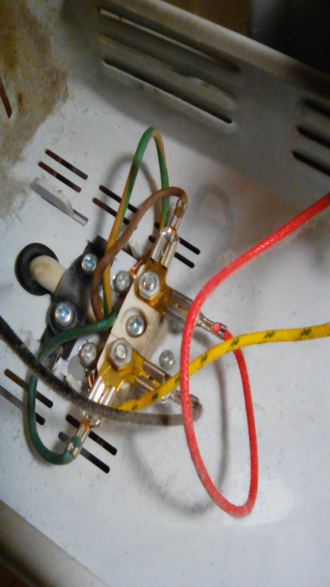
But everyone can wipe the connection elements with alcohol. All of them are made in the form of terminals, so it will not be a big problem to disconnect, wipe and reconnect them. It is important here not to confuse anything by installing the wire to a specific terminal.
The same goes for replacing parts of the power supply and security. It will be difficult to repair any of them with your own hands. And if you are not a specialist in this matter, then you are unlikely to succeed. Therefore, there is only one way out - to replace the failed elements with new ones. All of them are held by screws or brackets, so it won't be too difficult to remove them. Again, we remind you that your main task is not to confuse the connection wires. After all, the electrical circuit of the radiator is the basis for its correct and efficient operation.
How to disassemble an oil heater
At first glance, it seems that oil heaters are a monolith that is not intended for disassembly. But this is not so, you can disassemble it.
What can be useful for repairing an oil heater with your own hands and associated maintenance:
- a wedge-shaped object with which you can pry a plastic panel;
- screwdriver;
- tester or multimeter;
- sandpaper;
- soft cloth;
- alcohol, cologne or the like;
- file;
- brush.
Of course, the models of heaters are different, therefore, the standard parsing algorithm cannot be described. Inspect the heater control panel. Sometimes there are screws, brackets. Then the disassembly process will begin with them.
However, most often the plastic panel is secured by a spring latch. It is necessary to walk around the perimeter of the panel with a plastic (or any other, if only not to scratch the case) object. Gently, without sudden movements, so as not to break. By touch, you can determine where the latch is and, by pressing harder, bend it.
If you do not disassemble equipment very often, it is better to put a camera next to you and shoot the entire disassembly process. Then putting everything back together will be much easier. In addition, bolts and nuts are advised to be laid out in a row during disassembly. It will be easier to understand what was extracted for what.
But do not rush to disassemble the heater! Some breakdowns can be detected without looking into the device.
Tank repair
Oil heater Forte EW-RD
Although it is not recommended to repair the tank with your own hands, some DIYers still try to fix it. What do you need to know so that the result does not disappoint you?
- The oil is drained first. Pay attention to its grade. The fact is that when the body of the oil heater is repaired, some of the oil will spill out, and it will have to be replenished.At the same time, it is impossible to mix mineral oil with synthetic one. Its volume should be such that an air cushion remains inside the case. It is needed to expand the oil.
- Usually the metal body of the radiator is welded or soldered. The first option is preferable. But not every home craftsman has this opportunity, so many people choose soldering. Please note that when brazing the oil cooler, use silver, brass, or copper-phosphorus solder. Tin can not be used. A burner is required. During the soldering process, water is poured into the tank. After the end of the work, the case must be dried
- Oil is not poured into the repaired tank as usual. It must be evaporated at a temperature of + 90C. It is not recommended to do a higher temperature, as the oil will begin to oxidize.
Sometimes small holes in the body are closed with a threaded connection. The repair method is not very reliable, but it is acceptable as a temporary option. It is important here to seal the joint well. In the process of a reusable cycle - heating and cooling - any sealant will begin to crack, so that smudges cannot be avoided.
Repair of heating elements in the heater
As for replacing the heating element with your own hands, then this heating element is selected by power. And if you do decide to change it yourself, you will have to sweat. Flaring will not be so difficult, but re-flaring is a big problem. Some models of oil heaters are equipped with removable heating elements, which makes them easier to repair. But even in this case, it is necessary to devote a lot of time and attention to the junction of the case and the heating element. Any gaskets and sealants will not last long, and the likelihood that you will return to repair work again is very high.
It is better to use electric welding to close the hole in the tank. To do this, you need a thin sheet inverter. Before starting welding work, it is imperative to remove rust from the edges of the crack or hole. Repairing the tank in this way is the best option, which increases your chances of success.
Electric heater repair instructions
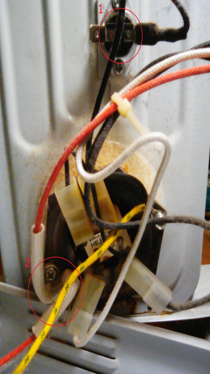
Repair of any electrical appliance begins with an external inspection. The first step is to check the power plug. It should not have visible mechanical damage, darkened plastic and cracks in the case. The pins of the plug must be firmly fixed in the body and free from blackening. The power supply cord must not be mechanically damaged. Especially carefully you need to inspect the place of the cord where it exits the plug body. At this point, the cords are often frayed.
It is also necessary to look through the mesh or perforation inside the heater body and make sure that there are no torn or burnt wires in the visible space, the wires are not burnt at the points of connection to the connectors and fixing with nuts, the heat heating elements (heating elements or nichrome spiral) do not have mechanical damage.
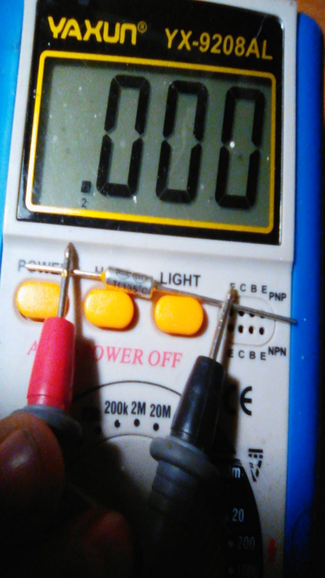
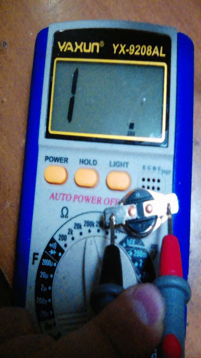
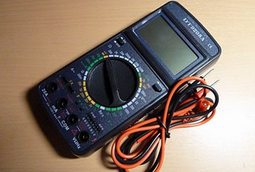
If an external examination did not reveal obvious defects, then a measuring device will be needed to further search for the causes of heater failure. The best for these purposes is a dial tester or multimeter, included in the low resistance measurement mode.
Without disassembling the heater, using a tester, you can check the serviceability of the power cord at the point where it exits the plug housing. To do this, set the heater switches (if any) to the operating position, connect the ohmmeter probes to the pins of the plug (conveniently using a crocodile clip), and press the cord to the plug body along the line of its exit from the plug, shake it from side to side. If the needle of the tester or the readings of the multimeter change even for a moment, then the repair is almost over. All that remains is to replace the plug.The resistance value of the heating element is, depending on the power of the heater, 10–150 Ohm and, if desired, you can calculate it accurately using the online calculator below.
Heater wiring diagrams
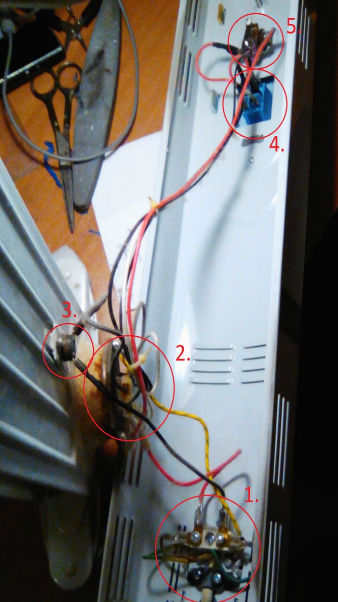
The photo below shows five standard, widely used electrical heater circuits.
Scheme No. 1 is the simplest, it is a power plug with a cord that is connected to the heating element directly or through a terminal block using a threaded connection or union terminals. According to this scheme, a tram stove type heater is assembled. To turn on a heater made according to this scheme, it is enough to insert the plug into the socket.
Scheme No. 2 differs from the previous scheme by installing a switch for convenience on the body of the electric heater. As a result, during operation, it is no longer necessary to insert and remove the plug from the socket every time to turn on or off the heater.
Heaters, assembled according to scheme No. 3, are supplemented with a thermal fuse, which will open the heater's power supply circuit if it overheats when it falls on the side or if things are placed on the heater for drying in violation of operating rules. In some models, in addition, in series with the thermal fuse, a position sensor is also installed, which turns off the heater if its position deviates from the operating one. Typically, the operating position of the heater is vertical.
Scheme 4 has two heating elements and an additional switch. Heating elements can be of the same power or different. Such a circuit solution allows you to adjust the power of the heater by simply turning on or off the switches, thereby regulating the heat generated by it. For example, if the heater is equipped with two heaters of 1000 and 2000 watts. Then, when On1 is turned on, the power will be 1 kW, when On2 is turned off, but On1 is turned on, the power will be 2 kW, and when On1 and On2 are turned on, it is already 3 kW.
For convenience, in some types of heaters, a wafer switch is installed. Turning the knob clockwise increases the power by 1 kW with each click.
According to the scheme No. 5, electric heaters of the type of fan heaters are made. An electric motor with an impeller is additionally installed in them. To prevent overheating of the heating elements, it is impossible to turn them on without turning on the fan. This is ensured by the additionally installed ON1 switch. In fan heaters, a self-healing thermal fuse must be installed to turn off the heating elements in the event of a fan failure. The fan heater can be used, if the heating elements are not turned on, like a normal fan for cooling in hot weather.
In expensive models of electric heaters, you can find a temperature controller. When the regulator sets the preset air temperature, when it is reached, the heater will turn off and turn on only after the air temperature drops below the preset value.
Indicators of operating modes on neon bulbs or LEDs can be installed in the electric heater circuit. In some models, illuminated switches are installed in which neon lights are already mounted. Indicators of direct participation in the operation of the heater do not take, but only signal about the mode of its operation.
How to disassemble an electric heater
If the heater stops heating and the external examination does not allow to establish the cause of the malfunction, then it will have to be disassembled for repair.
Consider the repair sequence using the example of a modern micathermic heater Bimatek PH300 (photo at the beginning of the article), assembled according to the most complex of the above electrical circuits. Knowing how to repair such a heater, simpler ones can be repaired without difficulty.
It is necessary to start disassembling from the side of the power cord entrance. Usually the cord will enter the cover from the side. To remove the side cover from the Bimatek PH300 heater, remove all visible screws holding the cover and two more countersunk screws. One of them is covered with a decorative cover, which is located below the control knobs.
To remove the plug, pry the plug from the side of the retainer with a screwdriver or knife blade, and move the retainer inward. The plug will come out easily.
A hole will open, in which there is a screw for the side fastening of the cover to the base. The second secret wine was hidden under a sticky sticker, next to which was another yellow sticker with a warning message “If the seal is damaged, the warranty is invalid!”.
So if the heater is still under warranty service and you are not confident in your abilities, if possible, it is better to contact the service center with a repair under warranty.
The side cover has been removed and all contacts of the controls and heating elements are now accessible. It remains only, with the help of a tester, to find and replace the failed part.
Principle of operation and complete set
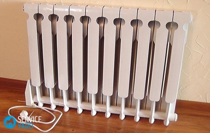
The device is based on a container filled strictly to a certain level with mineral oil.
Tubular electric heaters (heating elements) are located inside this container. Heating elements must be constantly immersed in oil, therefore, the installation of an oil heater is allowed only in a vertical position. If the heater falls and the heating elements are exposed, the latter may fail.
Work related to the replacement of heating elements, which means that with the need to drain and replace the oil, is usually carried out in specialized workshops (if you have experience and clean transformer oil, you can risk doing it yourself). If the oil tank is depressurized, it is better to trust the professionals, since this cannot be eliminated at home. Sometimes it will be cheaper to purchase a new heater.
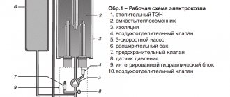
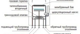
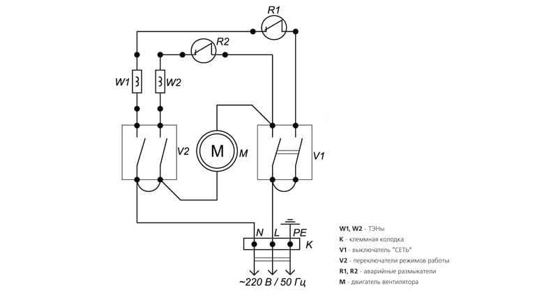
A simplified diagram of an oil heater is shown in Figure 1. A heating element consisting of 2 oil heaters, EK1 and EK2, is connected via a power switch V1 located on the oil heater housing. Depending on the number of heating elements turned on, its power consumption changes (the heating element switching circuit is shown conditionally and may differ).
The heated oil transfers heat to the housing, which acts like a normal radiator. The more sections it has, the faster heat transfer occurs. The air temperature level in the room can be smoothly changed, it is set using a bimetallic thermostat, indicated in the diagram as SK1. The heater must not be covered from above, otherwise the thermostat will simply turn off the device, reacting to the accumulation of hot air. Some models have special stands for drying clothes, but in general it is ineffective to use an oil cooler for drying.
The heating element connection diagram also contains a thermal switch (SK2), which protects the device body itself from overheating. A feature of oil heaters is the gradual heating of the air. In order to speed up this process somewhat, some models are equipped with built-in fans. The connection point of the fan motor M in the diagram is conventionally shown with arrows, since it is not an obligatory element of the device. The SA1 mains switch supplies power to the HL1 signal lamp.
From the author:
hello dear readers.Electric oil heaters are popular units in everyday life, characterized by a budget price and durability. But power surges, active or incorrect operation create a number of technical problems. Is it possible to repair an oil heater with your own hands or assemble it from available tools? The article lists the main types of unit malfunctions and how to resolve them.
Elimination of the most simple breakdowns
These breakdowns are oxidation, loosening of contacts, failure of the plug.
After disassembling the radiator, you need to check each wire. This is done with a multimeter or tester. First, check the serviceability of the plug. For this, one terminal of the tester is applied to one end of it. The second terminal of the tester must be attached to the connection between the thermal relay and the wire coming from the plug.
Sometimes there may be an extra connection on the power cable. It is done immediately after the cable enters the housing. Further from this connection the wires go to the thermostat and the heating element. The second terminal of the tester must be applied to each wire in this connection. Check both plug outputs.
If the tester did not give a signal when alternately applying the second terminal of the tester to the end of the input phase and neutral wire, then the plug is faulty. You need her replace.
After that, all other wires are checked with a tester. One of its terminals is always attached to the plug. The other applies to all terminals. The check sequence is as follows:
- thermostat contacts;
- thermal fuse contacts;
- contacts of the heating element operation regulator;
- contacts of the heating element.
During the check, the thermostat must be in such a position in which the heating element will work. It is exposed to a temperature that is higher than the available one.
If, when checking the output contact of the thermal relay, there is no tester signal, then the contact may be poor or the thermal relay has broken, or rather bimetallic plate... First pay attention to the contact. The wire terminal is pulled and checked. If it is clean, there is no oxidation or soot, then it is serviceable, and the problem lies in the base of the terminal attachment or thermal relay. If the terminal has the listed disadvantages, then it needs to be cleaned. In extreme cases, it is replaced with a new one.
All contacts can be visually checked. If the terminals are clean and undamaged, then the problem is not with them. Some of the contacts may be weakened. Then they are screwed up or the base into which the terminal is inserted is flattened or more flattened.
Repair of thermal relay and thermal fuse
This process consists in replacing the bimetallic plate or the whole item. The bimetallic plate must be replaced when it is strongly deformed, and any position of the relay wheel does not close the contact.
The bimetallic plate is changed as follows:
- Set the lowest heating temperature.
- Remove the regulator knob.
- Unscrew the nuts, dismantle the frame.
- Remove the bimetallic plate, put a new one in its place.
- Assemble the regulator.
- Check that the plate is working properly. This requires turn the regulator knob, changing the position of the plate and setting a certain temperature level... Next, the plate is heated with a hairdryer or fan heater to the set temperature level. If it bends and the contact is disconnected, then it is well seated. Otherwise, the replacement is incorrect. The difficulty must be solved by weakening the pressure of the plate on the contact, which corresponds to the lowest heating temperature.
Placing the plate in the desired position is a lengthy process. It's easier to buy a new thermostat.
Perform similar actions with a broken thermal fuse.
How to repair a breakdown?
So, to make it clearer for you how to proceed, we will provide instructions step by step:
What to do if the button doesn't work
Major breakdowns of electric convectors
That's all that I wanted to tell you about how to repair a convector with your own hands at home. We hope the provided tips helped you in solving the problem!
Checking the mode switch
If the power cord is in order, then proceed to check the heater operating mode switch.
The switch terminal, to which the brown wire fits, is common and is supplied with supply voltage. To check the switch, you need to set it to position III, in which the common terminal should be connected to the remaining two outputs. Now it is enough to measure the resistance between the common terminal and the other two, it should be equal to zero. If the switch is set to position II, the middle contact will remain connected to only one of the other two. In position I, only with untested contact. In the zero position, no contact should be connected to the other. If the switch is in order, then you need to look for the cause of the heater breakdown elsewhere.
Checking the operation of the bimetallic thermostat
A bimetallic thermostat is installed next to the mode switch. Its principle of operation is based on the properties of different metals, increase or decrease in size when the temperature changes in different ways. If you connect two plates of different metals into one whole, then when the temperature changes, the resulting plastic will begin to bend. And if an electrical contact is established on such a plate, then, thanks to the bending of the plate, it will be possible to control the temperature of turning on or off electrical appliances, depending on the ambient temperature. Each of us faces the useful property of bimetallic plates every day. For example, an electric kettle is turned off by a bimetallic plate heated by the steam of boiling water.
To check the health of the thermostat, just touch the multimeter probes to its terminals and turn the knob from stop to stop in either direction. In almost the entire range of rotation, the resistance of the thermostat should be zero. If this is not the case, then it is usually sufficient to clean the contacts, which are clearly visible from the side, with fine sandpaper.
If you need to remove the thermostat, for example, for replacement or repair, you must first remove the adjustment knob. It is kept on the axis due to a tight fit. To remove the handle, you must gently pry it on both sides with flat screwdriver blades. The handle is removed from the axle with a little effort.
There are two screws under the handle. It is enough to unscrew them and the thermostat mechanism will be released.
Checking the health of the heating elements
It is now the turn to check the heating elements connected to the switch and thermostat using a hinged six-pin connector.
As it turned out, the micathermic heating element is composite and consists of two. One has a resistance of 60 ohms, the other 100 ohms. To test the heating element, it is sufficient to measure the resistance between the red, blue and brown wires. The check showed the serviceability of the micathermic heater.
Vertical position sensor check
The position sensor is a weight attached to a lever with a balance spring engaged on the opposite end of the lever. When the heater is in an upright position, the weight stretches the spring and presses on the built-in microswitch. The supply voltage is supplied to the heating elements. If the heater is tilted on its side, the force of gravity will reduce the impact on the spring, the spring will move the lever away from the microswitch, the circuit will break, and the current will stop flowing to the heating elements.
There are two wires from the position sensor, white and brown. To check, it is enough to measure the resistance between them with a multimeter.When the heater is in a vertical position, the resistance of the position sensor should be zero. When tilted - infinity. The position sensor was found to be working properly.
Checking the health of the thermal fuse
It remains to check the thermal fuses connected in series, of which there were three and they were all installed behind the plate of the micrometric heater. A pair of white wires went from the thermal fuses to the six-pin connector, to the same one as the wires from the micathermic heater. A dialing test with a multimeter showed an open circuit in the thermal fuse circuit. It became clear that one of the thermal fuses was faulty.
It took further disassembly of the heater. To do this, I had to remove the second side cover and a protective mesh, which is removed after releasing the screws by shifting to the side. Access for testing two self-healing thermal fuses is now open.
To check the thermal fuses, you need to touch the white wire that fits the six-pin connector with one end of the multimeter probe, and with the second probe, piercing the insulation with the needle pressed against it, touch the wire connecting the thermal fuses. The test showed the serviceability of the fuses available for testing. All elements have been tested except for the thermal fuse behind the micathermic heating element. It means it is defective.
I had to remove the heating element, for which it was enough to unscrew four screws in the corners and take it to the side. The following view opened up.
The thermal fuse was located in a fiberglass tube and was attached to the heater body with a screw using a metal clamp.
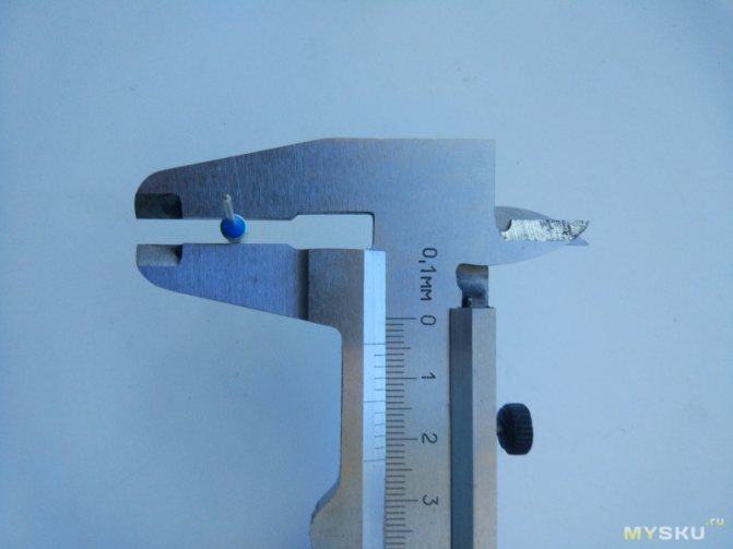
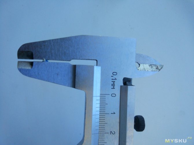
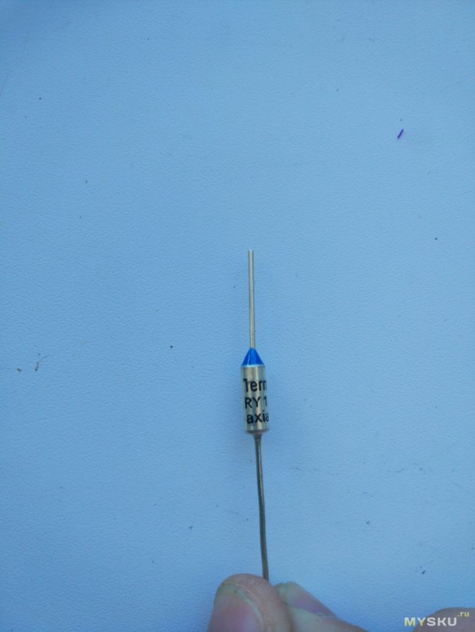
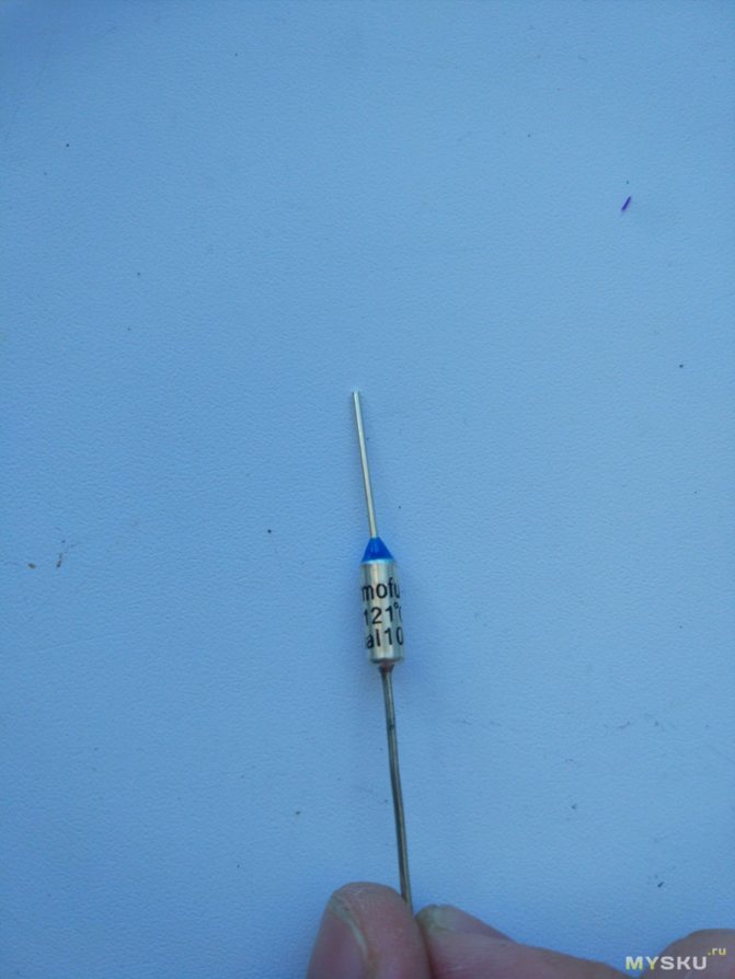
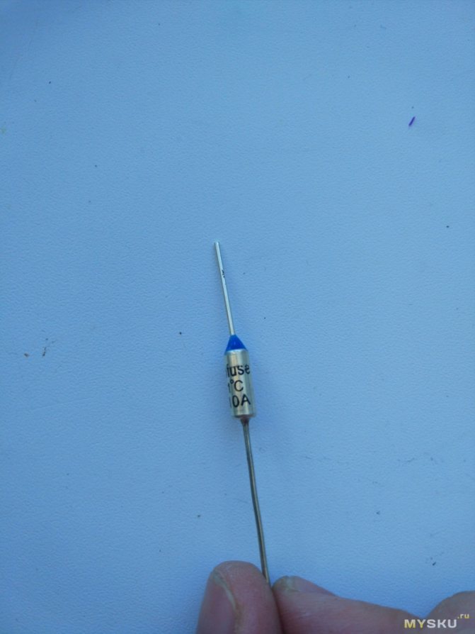
As it turned out, there was a self-healing SF192E thermal fuse in the tube, designed for a response temperature of 133 ° C and a load current of up to 10 A at a voltage of up to 250 V. An additional check with a multimeter confirmed the failure of the thermal fuse.
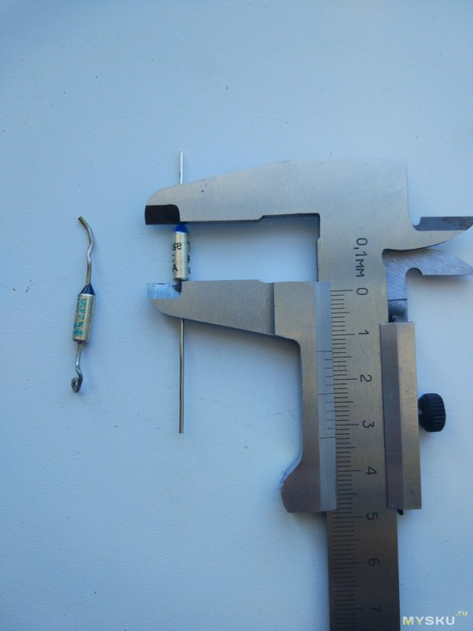
The thermal fuse was connected to the wires by crimping with a brass strip. Using an awl, the end of the strip on the side of the thermal fuse was bent, the thermal fuse was removed and a similar one, type G4A00, was pressed in its place, designed for a response temperature of 128 ° C and a load current of up to 10 A at a voltage of up to 250 V. The response temperature of the installed thermal fuse is 5 degrees lower than out of order. But taking into account the maximum heating of the heater body of only 65 ° C, such a replacement will not affect the protective functions and performance of the heater.
Before assembling the heater, all the connectors were connected to each other, the multimeter probes were connected to the pins of the power plug, and all operating modes of the heater were checked. The resistance in the position of the mode switch 0 was infinite, in position I it was 156 ohms, in position II –100 ohms and in position III - 56 ohms, which indicated that the heater was in full working order.
After assembly, the heater was connected to the network and confirmed to be operational. The repair of the heater is over and only traces from the tool left on the plastic plugs remind of its malfunction.