- Ultrasonic humidifiers of the LAURO series A novelty of the season - the ultrasonic humidifiers ROYAL Clima of the LAURO series are available for shipment ...
- Novelty 2020 ROYAL Clima VISTA Breeze - Climatic systems presented a novelty for 2020 - split-system ROYAL Clima VISTA series ...
- Annual conference on marketing OOO ‘BDR Thermia Rus’ on August 24 held the second annual Conference on marketing for ...
- Techno exhibition hall is open for guests Techno trade mark distributor LLC Trading House TechnoKlimat-SeveroZapad opened in St. Petersburg ...
- Updated Uponor Smatrix Wave range Today, the updated Smatrix Wave range allows you to control more than just underfloor heating and cooling ...
- Renga MEP. Let's get acquainted! Renga Software begins to introduce users to the new BIM software product Renga MEP, so that potential ...
- Aquatherm Almaty 2020 Exhibition Exhibitors will present a wide range of equipment and solutions from 170 leading global manufacturers and suppliers from 19 countries ...
- Expansion of the range of room thermostats Siemens has expanded the range of room thermostats for retail and shops….
- Vitovent 300-W air handling unit In August 2020, Viessmann presented a compact air handling unit in Russia ...
- The leadership of the REHAU group of companies changed. William Christensen became the new Chief Executive Officer of the concern, and ...
- Huge Sun Ray Collector for 220 Households in Melbourne What if the renewable energy infrastructure was functional and beautiful? ...
- In wind power, as opposed to solar, downtime ... Vaisala has long recommended a balanced portfolio of renewables ...
- Leaders of the world fuel and energy complex will meet in Moscow 130 businessmen have already confirmed their participation in the Russian Energy Week International Forum ...
- The championship is over. Long live the Championship! Exactly one year remains to prepare for the WorldSkills World Championship ...
- BOILERS AND BURNERS - 2020 On October 2-5, St. Petersburg will host the 16th International Exhibition on Thermal Power Engineering, which will present the most modern ...
- Lemax does not hide anything from its consumer. The manufacturer of heating and water heating equipment conducts study tours ...
- TVZ was interested in PROFACTOR TM products. The company's engineering plumbing was interested in Tver Carriage Works OJSC ...
- Top honors for Wilo Two of the largest corporate reporting and brand management agencies have recognized the company with the prestigious Platinum and Gold Awards ...
- Evolution program promotes competitiveness Lumière du Soleil marketing agency has launched the Evolution gratis program for Russian enterprises ...
- The 300th FRISQUET boiler was installed in the Glagolevo Park settlement. The boiler was supplied by, which specializes in designing ...
- We invite you to the opening of Techno representative office In St. Petersburg on August 23 at 12:00 a showroom will open, where Techno convectors will be presented ...
- There will be 40 million charging stations in the world by 2030 Due to the growing demand for electric vehicles around the world, the demand for recharging will increase and it will be installed before ...
- Will mass production of assemblies reduce the cost of foundations for offshore wind turbines? How can a prototype remain as strong ...
- Danfoss Eco ™ Recognized for Best Design Again The Danfoss thermostat, already recognized by several prestigious juries, has won a new Red Dot ...
- New impeller for improved suction performance KSB has developed a special impeller for multistage pumps ...
- LG Electronics specialists summed up the results of the past year LG Electronics specialists and HVAC equipment professionals summed up the results ...
- A Practical Guide to Roof Boiler Houses The BDR Thermia Rus company has issued a guide to roof boilers summarizing the experience of using ...
forum.c-o-k.ru
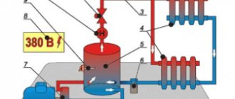
The role of the collector in heating
When arranging a water pumping unit, it is necessary to adhere to the rule: the total sum of the diameters of all branches should not exceed the diameter of the supply line.
We apply this law to the heating system, but it will look like this: the boiler outlet nozzle with a diameter of 1 "is allowed for use in a two-circuit system with pipes with a diameter of ½".
For a house with a small cubic capacity that is heated exclusively by radiators, this kind of system is considered productive.
In practice, a private cottage is equipped with a more modernized heating circuit, where additional circuits are equipped:
- underfloor heating system;
- heating of several floors;
- utility rooms, etc.
When the branch is connected, the level of the operating pressure in the circuits becomes insufficient for high-quality heating of all radiators, respectively, and the comfortable atmosphere mode will be violated.
In this case, a balancing unit is equipped with a distribution manifold for a branched heating main. Using this method, it is possible to compensate for the cooling of the heated coolant, which is characteristic of traditional one- and two-pipe schemes.
By means of equipment and valves, the required parameters of the coolant temperature are set for each of the lines.
Hydraulic calculation of heating pipelines using programs
Calculating the heating of a private house is a rather complicated procedure. However, special programs make it much easier. Today, a selection of several online services of this type is available. The output is the following data:
- required diameter of the pipeline;
- a specific valve used for balancing;
- dimensions of heating elements;
- pressure drop sensor values;
- control parameters of thermostatic valves;
- numerical settings of the regulating parts.
Oventrop co program for the selection of polypropylene pipes. Before starting it, it is necessary to determine the required equipment elements and set the settings. At the end of the calculations, the user receives several options for the implementation of the heating system. Changes are made to them iteratively.
Calculation of the heating network allows you to choose the right pipes and find out the flow rate of the coolant
This hydraulic calculation software allows you to select the pipe elements of the pipeline of the required diameter and determine the flow rate of the coolant. It is a reliable assistant when calculating both one-pipe and two-pipe designs. Convenience of work is one of the main advantages of Oventrop co. The set of this program includes ready-made blocks and catalogs of materials.
HERZ CO program: calculation taking into account the collector. This software is freely available. It allows you to make calculations regardless of the number of pipes. HERZ CO helps to create projects for renovated and new buildings.
Note! There is one caveat here: a glycol mixture is used to create structures. The program is also focused on the calculation of one- and two-pipe heating systems
With its help, the action of the thermostatic valve is taken into account, as well as the pressure loss in heating devices and the indicator of resistance to the flow of the coolant are determined.
The program is also focused on the calculation of one- and two-pipe heating systems. With its help, the action of the thermostatic valve is taken into account, as well as the pressure loss in the heating devices and the indicator of the resistance to the flow of the coolant are determined.
The calculation results are displayed graphically and schematically. Help function is implemented in "HERZ CO". The program has a module that performs the function of finding and localizing errors. The software package contains a catalog of data on heating devices and fittings.
Instal-Therm HCR software product. With this software it is possible to calculate radiators and surface heating. Its delivery set includes the Tece module, which contains subroutines for designing various types of water supply systems, scanning drawings and calculating heat losses. The program is equipped with various catalogs that contain fittings, batteries, thermal insulation and a variety of fittings.
The length of the pipeline is important for calculations
Computer program "TRANSIT". This software package allows for multivariate hydraulic calculation of oil pipelines, in which there are intermediate oil pumping stations (hereinafter referred to as OPS). The initial data are:
- absolute roughness of pipes, pressure at the end of the line and its length;
- elasticity and kinematic viscosity of saturated oil vapors and its density;
- brand and number of pumps switched on both at the head station and at intermediate pump stations;
- pipe layout according to the size of the diameter;
- pipeline profile.
The result of the calculation is presented in the form of data on the characteristics of the gravity sections of the mainline and on the pumping flow rate. In addition, the user is given a table displaying the pressure value before and after any of the NPS.
In conclusion, it must be said that the simplest calculation methods were given above. Professionals use much more complex schemes.
Main characteristics of the collector system
The main difference between the collector and the standard linear method of redistribution of the heat carrier is the division of flows into several channels independent from each other. Various modifications of collector units can be used, differing in configuration and size range.
The design of the welded manifold is quite simple. The required number of nozzles is connected to the comb, which is a round or square pipe, which, in turn, are connected to the individual lines of the heating circuit. The collection unit itself is interfaced with the main pipeline.
Also, shut-off valves are installed, through which the volume and temperature of the heated liquid in each of the circuits is regulated.
The positive aspects of operating a heating system based on a distribution manifold are as follows:
- The centralized distribution of the hydraulic circuit and temperature indicators is uniform. The simplest model of a two- or four-loop type ring comb can balance the performance quite effectively.
- Regulation of operating modes of the heating main. The process is reproduced due to the presence of special mechanisms - flow meters, mixing unit, shut-off and control valves and thermostats. However, their installation requires correct calculations.
- Convenience of service. The need for preventive or repair measures does not require shutting down the entire heating network. Due to the sliding pipeline fittings mounted on each separate circuit, it is possible to easily shut off the flow of the coolant in the required area.
However, there are also disadvantages to such a system. First of all, the pipe consumption increases. Compensation of hydraulic losses is carried out by installing a circulation pump. It is required to be installed on all collector groups. In addition, this solution is relevant only in closed-type heating systems.
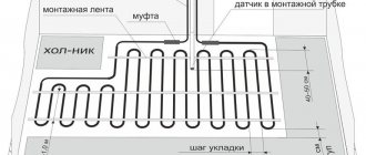
How many solar collectors do you need to heat your home?
Regardless of which heating system is installed in the house, the heat loss will be the same. For an accurate calculation, it is better to contact the specialists, but to obtain approximate data, you can use the online services https://teplo-info.com/otoplenie/raschet_teplopoter_online.
By dividing the data obtained by the P value calculated using the last formula, you will find out how many solar collectors or square meters of collectors you need to heat your house in winter.
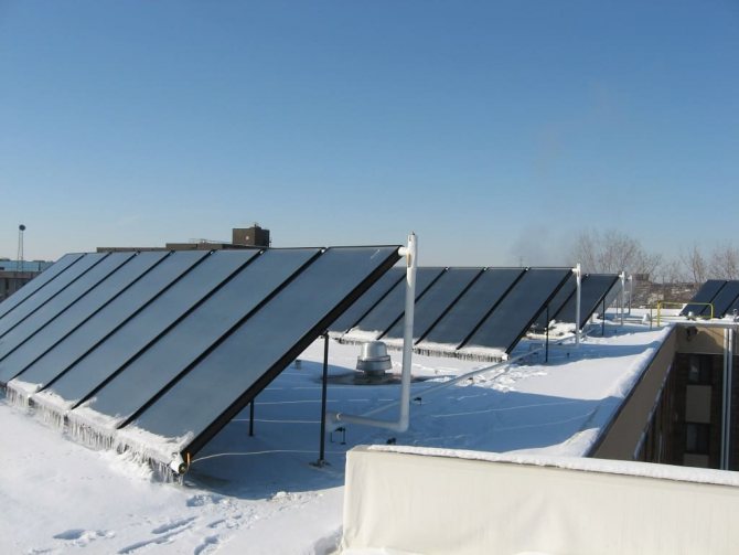
Separately, it is worth recalling that in the cold season there are nuances with the operation of solar collectors. You can learn more about this in the article "How a solar collector works in winter - efficiency, problems and solutions."
The main problem with the snake is to clean the collectors from the cold.
Manifold unit modifications
Before proceeding with the collection of the manifold assembly, it is necessary to determine its functional load. The equipment can be installed in several sections of the heating main. Based on this, the necessary equipment, dimensions and level of automation of the working cycle are selected.
In fact, two devices are required for the full operation of such a node. With the help of a comb, the heat carrier is distributed along the contours from the central supply pipeline. The return collector channel is represented by a collection mechanism and a point where the cooled liquid is sent to the boiler.
The installation of a home-made distribution group may be required when arranging water-heated floors or to prepare standard heating with radiators.
Distinctive features of both options are their sizes and accessories:
- Boiler room... The welded manifold group is manufactured from pipes with a diameter of up to 100 mm. A circulation pump and shut-off valves are installed on the supply. The return ring is equipped with shut-off ball valves.
- Underfloor heating system... A similar equipment is present in this mixing unit. With its help, it is possible to significantly save on the consumption of the heat carrier, especially if additional flow meters are installed.
Each of these solutions provides for an individual installation scheme. Correct installation of all elements can be carried out only after detailed calculations of all parameters of the operating point.
There are also differences in the required number of circulation pumps. In the boiler room, each line is equipped with this device. For underfloor heating only one is provided.
On the Internet and in general all over the world there is a total delusion in the calculations of the hydraulic arrow. The diameter of the hydraulic arrow is selected based on the diameters of the inlet nozzles. That is, the diameter of the hydraulic arrow is equal to three diameters of the inlet pipe. This is a total delusion of calculation.
Because of this well-promoted calculation, everyone has a stupor about the work of the hydro-shooters.
In the video, I told and showed examples of calculating the diameters of hydraulic arms and collectors. It turns out that the diameter of the hydraulic arrow can be reduced to the diameters of the inlet pipes. And create simple tee water arrows. Do you now understand how many people in the world are mistaken?
Make no mistake gentlemen plumbers ...
Watch the video:
Can't watch the video?
More about the program
| Like |
| Share this |
| Comments (1) (+) [Read / Add] |
A series of video tutorials on a private house
Part 1. Where to drill a well? Part 2. Arrangement of a well for water Part 3. Laying a pipeline from a well to a house Part 4. Automatic water supply
Water supply
Private house water supply. Principle of operation. Connection diagram Self-priming surface pumps. Principle of operation.Connection diagram Calculation of a self-priming pump Calculation of diameters from a central water supply Pumping station of water supply How to choose a pump for a well? Setting the pressure switch Pressure switch electrical circuit Principle of operation of the accumulator Sewerage slope for 1 meter SNIP Connecting a heated towel rail
Heating schemes
Hydraulic calculation of a two-pipe heating system Hydraulic calculation of a two-pipe associated heating system Tichelman loop Hydraulic calculation of a single-pipe heating system Hydraulic calculation of a radial distribution of a heating system Diagram with a heat pump and a solid fuel boiler - logic of operation Three-way valve from valtec + thermal head with a remote sensor Why does the heating radiator in a multi-apartment building do not heat well? home How to connect a boiler to a boiler? Connection options and diagrams DHW recirculation. Principle of operation and calculation You do not correctly calculate the hydraulic arrow and collectors Manual hydraulic calculation of heating Calculation of a warm water floor and mixing units Three-way valve with a servo drive for DHW Calculations of DHW, BKN. We find the volume, power of the snake, warm-up time, etc.
Water supply and heating constructor
Bernoulli's equation Calculation of water supply for apartment buildings
Automation
How servos and three-way valves work Three-way valve to redirect the flow of the heating medium
Heating
Calculation of the heat output of heating radiators Radiator section Overgrowth and deposits in pipes worsen the operation of the water supply and heating system New pumps work differently ... connect an expansion tank in the heating system? Boiler resistance Tichelman loop pipe diameter How to choose a pipe diameter for heating Heat transfer of a pipe Gravitational heating from a polypropylene pipe Why do they not like single-pipe heating? How to love her?
Heat regulators
Room thermostat - how it works
Mixing unit
What is a mixing unit? Types of mixing units for heating
System characteristics and parameters
Local hydraulic resistance. What is CCM? Throughput Kvs. What it is? Boiling water under pressure - what will happen? What is hysteresis in temperatures and pressures? What is infiltration? What are DN, DN and PN? Plumbers and engineers need to know these parameters! Hydraulic meanings, concepts and calculation of heating systems circuits Flow coefficient in a one-pipe heating system
Video
Heating Automatic temperature control Simple top-up of the heating system Heating technology. Walling. Underfloor heating Combimix pump and mixing unit Why choose underfloor heating? Water heat-insulated floor VALTEC. Video seminar Pipe for underfloor heating - what to choose? Warm water floor - theory, advantages and disadvantages Laying a warm water floor - theory and rules Warm floors in a wooden house. Dry warm floor. Warm Water Floor Pie - Theory and Calculation News to Plumbers and Plumbing Engineers Are you still doing the hack? First results of the development of a new program with realistic three-dimensional graphics Thermal calculation program. The second result of the development of Teplo-Raschet 3D Program for thermal calculation of a house through enclosing structures Results of the development of a new program for hydraulic calculation Primary secondary rings of the heating system One pump for radiators and underfloor heating Calculation of heat loss at home - orientation of the wall?
Regulations
Regulatory requirements for the design of boiler rooms Abbreviated designations
Terms and Definitions
Basement, basement, floor Boiler rooms
Documentary water supply
Sources of water supply Physical properties of natural water Chemical composition of natural water Bacterial water pollution Requirements for water quality
Collection of questions
Is it possible to place a gas boiler room in the basement of a residential building? Is it possible to attach a boiler room to a residential building? Is it possible to place a gas boiler room on the roof of a residential building? How are boiler rooms divided according to their location?
Personal experiences of hydraulics and heat engineering
Introduction and acquaintance. Part 1 Hydraulic resistance of the thermostatic valve Hydraulic resistance of the filter flask
Video course Calculation programs
Technotronic8 - Hydraulic and thermal calculation software Auto-Snab 3D - Hydraulic calculation in 3D space
Useful materials Useful literature
Hydrostatics and hydrodynamics
Hydraulic Calculation Tasks
Head loss in a straight pipe section How does head loss affect the flow rate?
miscellanea
Do-it-yourself water supply of a private house Autonomous water supply Autonomous water supply scheme Automatic water supply scheme Private house water supply scheme
Privacy Policy
Distribution unit design
There is simply no universal scheme for a beam-type heating project. Each case is individual, therefore, the unit is completed with the necessary devices in a private way. However, it is worth reading the general guidelines and rules.
Comb installation rules
Collector installation is not possible in the apartment. However, there is an exception to the rule - in some houses, when arranging all communications, additional valves are mounted, through which the heating circuits are connected. Such a device allows for individual manifold wiring.
The schematic arrangement of heating should be drawn up in such a way that the location of the Mayevsky tap is on the comb. This option is considered optimal, since over time, accumulated air will need to be released from the circuits.
Features of the beam group
The beam wiring group has many features, but some of them are also characteristic for heating of another modification:
- The circuit must include a compensation tank with a volume of more than 10% of the total volume of the heat carrier.
- The optimal location of the expansion tank is on the return pipeline in front of the circulation pump, since there is a lower temperature regime.
- If a thermo-hydraulic distribution is used, the circuit is designed so that the tank is located in front of the main pump, which is responsible for the forced movement of water in the boiler piping.
- The circulation pump is installed in a strictly horizontal position. If you do not adhere to this rule, at the first airlock, the device will lose cooling and lubricant.
The distribution group can be assembled from various materials: polypropylene or metal. The selection is carried out based on the skills of work and the availability of tools for connecting parts.
The process of selecting pipes for the installation of a distribution group is also considered important. The main factors taken into account when choosing contour elements:
- Purchase of pipes only as a solid element - in coils. Due to this, connections are not made in the wiring installed under the concrete screed.
- Heat resistance and tensile strength must be determined individually, based on the technical data of the heating system.
Due to the predictability of the performance of autonomous heating, polypropylene pipes can be used. They have no unwanted connections and are sold in one-piece 200m lines.
The material is thermally stable and can withstand up to 95 ° C with an allowable burst pressure of 10 kg / 1 cm2.
For a multi-storey building, it is preferable to choose a stainless steel corrugated pipe.This material shows excellent technical capabilities to cope with such a load:
- heated coolant up to 100 ° C, which is more than enough for the heating circuit;
- pressure up to 15 atm .;
- breaking pressure up to 210 kg / 1 cm2.
Fittings designed for polypropylene can be plastic or made of brass. The spigot connection is equipped with a retaining ring, which is threaded onto the pipeline.
An important characteristic of polypropylene pipes is memory for mechanical processing, as a result of which plastic deformation of the substance occurs.
For example, when the pipes are stretched with an extender and the fitting is inserted into the connector, after a certain time the pipe will return to its previous state and crimp the part. The contact can be fixed with a retaining ring.
Calculation of the heating manifold
Initially, for the manufacture of a thermo-hydraulic comb, you will need to calculate its main parameters - the length, cross-sectional diameter of the branch pipes and the number of branches of the heating main. You can calculate these characteristics yourself or use special software.
The hydraulic balance of the structure is the main condition to be observed. Applying the rule of three diameters for the hydraulic separator, it is necessary to perform the following action - sum up the cross-sectional diameter of the connected circuits.
As a result, we get an amount equal to the diameter of the main pipe connecting to the supply line. The use of this principle reduces the likelihood of imbalance in the entire heating system.
A special cabinet or case is used as a place for a distribution unit. When arranging the system, it is necessary to adhere to the permissible minimum distance between the two heat-conducting lines of the inlet and outlet - 6 diameters.
The issue of the correct selection of the performance of the circulation pump is also relevant. To do this, it is necessary to calculate the specific rate of water consumption of the system and, based on the results, select the pump. If the scheme is complicated by several combs, the calculation is performed for each individual contour and in general for the entire system.
Self-assembly of equipment can be carried out by means of a pipe with any kind of cross-section. This aspect does not affect the functioning of the device and does not increase local losses. They will be compensated by the circulation pump.
Node calculation
Before drawing up a drawing of the unit, it is necessary to calculate the number of heating circuits: radiator, underfloor heating, water heating for domestic needs. Each circuit has a supply and return of the coolant, respectively, a scheme with two combs and the required number of inlet and outlet nozzles is calculated.
Next, you need to make a preliminary drawing of the comb. The principle of calculating the comb diameter implies the use of the generally accepted formula (as an example, a 4-contour node is used):
D0 = D1 + D2 + D3 + D4, where
D0 - diameter of the comb pipe,
D1… 4 - cross-sectional diameters of the branch pipes.
The formula is also universal when making a collector with your own hands.
Then the final assembly diagram is drawn up, where each pipeline group and additional devices are precisely indicated.
It is advisable to install the manifold for heating in a special cabinet. The purpose of the cabinet is to hide the node, close unauthorized access and provide an opportunity to decorate the room without obstacles.
The cabinet model can be external or built-in. Based on the drawing drawn up, you need to calculate the width of the comb plus the dimensions of additional devices (hydraulic pump, hydraulic arrow, etc.), then determine the height of the comb - this will be the minimum cabinet height. It is imperative to add up to 50 cm to the resulting dimensions and choose a cabinet according to these parameters or make it yourself.
Component selection rules
After completing all the calculations, the next step will be the selection of the required set of mechanisms. The simplest set consists of valves. However, with such a device, it is difficult to regulate the power of individual heating lines.
To solve this problem, crane axle boxes are installed on the feed comb, through which smooth adjustment is possible. Rotameters are mounted on the return manifold.
For warm water floors, the configuration will be different. The assembly will require the following elements:
- Shut-off and control valve. Installation is carried out on connecting pipes. With the help of this valve, a complete or partial stop of the flow of the coolant is carried out. It is recommended to use automatic modification.
- Rotameters. Such elements are mounted on a return manifold. They perform a similar function as the previous element, only in the return pipe.
- Mixing unit. By mixing the streams of hot and cold water, the preset operating mode of heating is optimized.
The manifold kit is necessarily equipped with a safety group headed by a pressure gauge, an air valve, a thermostat and a circulation pump. It can be supplemented with servos, the control of which is reproduced through the control electrical unit. Thus, the work of the system can be automated.
The subtleties of self-assembly
Before making the collector, it is necessary to draw up a diagram with the location of all the elements of the assembly. It is better to choose steel pipes with a square section as a material of manufacture. This type is easy to process, which significantly reduces labor costs for the installation of nozzles.
The step-by-step production process for the prefabricated switchgear assembly is as follows:
- Layout and cutting of the main body. According to the design scheme, it is necessary to mark the profile pipe. With the help of a gas cutter, holes are made in the marked areas.
- Preparation of connections. A thread is cut on the branch pipes by means of a die.
- Completion. Next, the prepared pipe sections are welded to the body. Their fixation must be carried out by tacking spot welding. Then, in the main welding, the workpieces are welded along the edges.
- Fasteners. Brackets for fastening are welded to the block.
- Cleaning and finishing. After stripping, the body is primed and covered with heat-resistant paint for metal products. The supply and return circuits are painted with two different colors for ease of identification.
If polypropylene pipes are used for manufacturing, you should pay attention to the presence of a reinforcing layer in them. In its absence, the plastic structure may be subject to deformation from the existing temperature regime.
For those who do not have special tools available, a comb can be assembled from individual pre-fabricated elements. It is better to select components from the same company.
Installing a comb in the heating system
The primary task is to check the distribution manifold for tightness of the connections. The installation is implemented according to the design scheme. Depending on the material used for the manufacture of the main unit, the connection conditions are determined.
The choice of connection technology depends entirely on the modification of the device used.
In addition to maintaining the level, during installation it is necessary to follow the following rules:
- electric and gas boilers are connected to the upper or lower branch pipes;
- a circulation pump is mounted at the end of the structure;
- the connection of the circuits can be carried out at the top or bottom of the comb;
- indirect heating devices and boilers operating on solid fuels must be connected to the distribution group from the side;
- the entire hydraulic separation unit for the underfloor heating system is placed in a protective box - this reduces the risk of damage to the constituent elements of the collector.
At the final stage, it is necessary to carry out a control start of heating in order to timely determine the hidden or obvious shortcomings of the design made.
Design features of the heating comb
The collector device is actually two combs (supply and return). What can be included in its design:
- Combs directly;
- Flowmeters;
- Thermal heads;
- Terhokhodovye valves;
- Hydrostrel;
- Air vent;
- Cranes;
- Shut-off valves;
- Galvanized brackets.
Depending on the complexity of the unit and the number of circuits, the equipment and device may vary. The main parts are the distribution manifold of the heating system, valves and taps. Flowmeters can also be useful, the principle of which is visual adjustment of the flow rate of the coolant, especially for systems in which there are several circuits.
The collector can be designed with your own hands, for which you will need polypropylene parts (pipes, tees, etc.) and a set of valves, as well as any other device at the discretion of the homeowners. Polypropylene pipes must be soldered. You can use the simplest stainless steel comb with taps on one side. However, it should be understood that, at first glance, a simple structure may require complex repairs after a short period of time or complete replacement, which will entail large costs.
Advice! You should not save on the heating comb, since this is the basis of the unit, it is better to choose a multifunctional comb and put plugs on unnecessary pipes and outlets than to endlessly repair the collector with your own hands.
Useful video on the topic
Detailed technical process for assembling the manifold group:
Ready-made combs for arranging underfloor heating, equipped with not always the necessary functionality, due to their high cost, are not available to the wide masses of users. Let's see how to assemble a budget version of the design with our own hands:
The distribution group can also be implemented using polypropylene pipes. How to do this, you can learn from the video:
Correct selection of all components and installation of the manifold assembly is the key to efficient and reliable operation of the heating main. Due to the minimum number of connections, the possibility of leaks is minimized. Special comfort comes from the ability to control and adjust each heating circuit.
sovet-ingenera.com
Calculation formula
In the form of a formula, the area rule will look like this:
S0 = S1 + S2 + S3 + Sn,
where S0 is the cross-sectional area of the comb,
S1-Sn - cross-sectional areas of outgoing branches.
The pipelines included in the hydrocollector are not taken into account.
This formula can be brought into a more understandable form, remembering the school geometry course. The section is calculated using the formula S = π * r², but for simplicity and convenience, it is better to calculate the collector through the diameter: S = π * d2 / 4. Following this formula, the original equality is converted to this construction:
π * d02 / 4 = π * d12 / 4 + π * d22 / 4 + π * d32 / 4 + π * dn2 / 4,
where d0 denotes the diameter of the comb,
d1-dn - internal dimensions of the branch branches.
Reducing the number Pi and putting everything under the square root sign, you can greatly simplify the calculations:
d0 = 2 * √ (d1² / 4 + d2² / 4 + d3² / 4 + dn² / 4).
This is how a universal formula is derived, suitable for calculating a hydrocollector of any complexity and configuration. If all the outgoing heating branches are of the same size, the equality becomes even more simplified:
d0 = 2 * √ (d1² / 4 * N),
where N denotes the number of branches branching from the comb.
In addition to the dimensions of the collector pipes, the distances between them must also be taken into account. So, the distance between the inlet and outlet groups of branches should be equal to six diameters, and the branches of the heating circuits should be separated from each other by three sizes.
Let's connect hot water supply?
In addition to heating, hot water can be connected to the solar collector system.To do this, let's calculate how much heat energy you need to spend every day. The formula for calculating the solar collector for DHW is simple:
Pw = 1.163 x V x (T - t) / 24
Legend:
- Pw is the amount of heat required to heat water;
- V is the average volume of hot water consumed per day;
- T is the temperature to which you need to heat the water;
- t is the temperature from which water enters the system.
To calculate the required number of additional DHW collectors, divide this value by the solar collector capacity P, obtained using the last formula.
Choosing the right pipe diameter
H2_2
It is not enough to disassemble the calculation scheme for the comb diameter in order to assemble an effective hydrocollector. It is also necessary to understand what diameter the pipes must be in order to maintain the balance of the system. The selection of pipes is based on their inner diameter, which determines the cross-sectional area and throughput, that is, the amount of water that can pass through the heating system per unit of time.
It is believed that in order to ensure a comfortable temperature, the branches extending from the collector should give off 1 kW of heat for every 10 m2 of the room. Usually, a 20% margin is provided in case of excessive frost, that is, 1.2 kW is needed for every 10 m.Taking into account that the optimal speed of movement of the coolant is 0.4-0.7 m / s, and its temperature is 80 degrees, for a room with an area of 20 m2, pipes with a cross section of about 10 mm are needed. The flow rate of water leaving the hydrocollector will be 110 l / h.
The calculation of all these figures is carried out according to a complex formula, which is easier to replace with a table. Using the table, you can easily correlate the size of the room with the required size of the pipelines, knowing the required heat output of the system.
The simplified calculation scheme looks like this: D = √354 ∙ (0.86 ∙ Q: Δt): V, where:
- D is the pipe diameter in centimeters;
- Q is the thermal power of heating in kilowatts (1.2 kW for every 10 m2);
- Δt is the temperature difference between the supply from the comb (80 degrees) and the return (usually 65-70 degrees);
- V - water speed in m / s (0.4-0.7 m / s in the optimal version).
Separately, it is worth noting the required power of the pumping unit installed in the hydrocollector. It makes the water circulate inside the heating system. It is based on the flow rate, which, in turn, depends on the water flow rate and pipe diameter and is measured in m3 / h.
Notes (edit)
If the table with calculations of solar energy in various regions of the Russian Federation does not contain accurate information about the region in which you live, then you can use the information that is indicated on the insolation map of Russia. This will allow you to find out the approximate value of the received heat energy per square meter.
Empirically determined: to calculate the insolation for the most optimal angle of inclination of the solar collector, the data indicated for the selected area should be multiplied by a factor of 1.2.
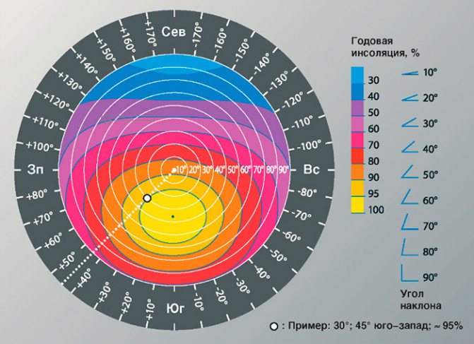
Determination of the angle of inclination of solar collectors
For example, the table indicates that for Moscow the value of energy that is available during daylight hours is 2.63 kW * h / m2. In other words, the available annual energy is 2.63 * 365 = 960 kW * h / m2.
Thus, with the optimal slope of the site in Moscow, the collector will generate approximately 1,174 kWh / m2.
Of course, this calculation method is not highly scientific, however, on the other hand, the data obtained can be used to determine the required number of vacuum tubes at the household level.
Calculation example
To make the reservoir calculation formula more clear and understandable, it is worth considering an example situation. Let's say you have a house with an area of 100 sq. m., which has two heating circuits and one heating circuit for domestic use. Accordingly, three branches will be included in the hydrocollector. It is necessary to calculate the required size of the comb so that there is enough hot water for all circuits of the system.
The inner diameter of the collector pipes can be found from the tables of correspondence of diameters and materials from which they are made, or you can calculate it yourself using a simple ruler. For example, let's take a size equal to 20 mm. All three pipes of the system will be the same for us. You need to substitute the number 20 in the previously derived formula, and then it turns out:
d0 = 2 * √ (202/4 * 3) = 2 * √300 ≈ 36 mm
Important! Note that if a fractional number is obtained after extracting the root, it should be rounded up so that the size of the comb will probably fit.
In the example shown, the internal diameter of the collector must be at least 36 mm. You can choose the right material for the pipe that forms the hydrocollector from the same tables, or by consulting in hardware stores.
domotopim.ru
Unfortunately, it is impossible to explain in detail on all points within the framework of the forum, and citing evidence. And although some people usually take offense at such an answer, all the same, I have to say that the only way to understand all this is to read, read and read the textbooks again. It is impossible to copy and paste all the textbooks here in response.
Therefore, I tried to show you the directions where you made a mistake and where you should go, so that you can figure it out on your own with the help of search engines and textbooks.
But in a nutshell it is impossible to teach this, excuse me. For example, a trainer at a fitness club has advised you to work out certain muscle groups. But the coach will not be able to work them out for you.
On some points you immediately began to argue. But there is neither time nor desire to argue with you and prove something. Just think that if you were given advice, then there was a reason for it. It's up to you to use them or not. And only you decide whether you need to study these issues or not. But since you are doing the project yourself, and have not hired a competent designer, then I assume that you still need it.
Additional answers:
1. Yes. Up to +75 on the boiler feed for a cold five-day period. If you do not want the pipes to crack after a while. 2. Only you know if you will have all the pipes covered with thermal insulation. And what kind of insulation. And where will be laid. If the pipes are not thermally insulated, then the value should also be 0%. And as you indicated, the thermal insulation of ALL pipes is absolutely 80%, but this cannot be. This means that this is a gross mistake that will lead to incorrect results, including the wrong choice of the power of the OP. I hope you don’t start asking why this cannot be. 3. Why was it necessary to make such long "guts" dead-end branches around the perimeter of the house? Couldn't it have been divided into two "dead-end" lines on each floor? 4. Once you started designing a heating system, you should know the terms. What, for example, is a radio engineer who asks to explain to him what Ohm's law is, and what are current, voltage and resistance? If you take up the development of CEA, then referring to ignorance of Ohm's law is generally nonsense. Now you don't need to walk around the reading rooms, as we did in the early 80s. Find and read with a search engine (textbooks, not forums) without taking your fifth point off your chair. 5. So read in the textbooks what the terms indicated in the calculation parameters of the system mean. And set their values not thoughtlessly, but realizing what you want to get, and how these parameters will affect the calculation. 6. And who should study and understand this for you? For example, when using propylene glycol antifreeze with a concentration of 30%, it is prohibited to make a setting of more than +70 degrees at the boiler feed. You consider the boiler feed setpoint +90 !!! And instead of immediately asking counter-questions "Why?" or "And why does my neighbor stand and not fall ...?" - open literature and study. Who will work on your own muscle groups for you? 7. "Silently" serve. Generally a strange question. And they themselves must understand why GB cannot be installed after the shut-off valve.If you do not understand, then it is unlikely that anyone will want to write explanations on many pages. Take and finally read literature, not forums. 8. Well, if you think the need to use a parachute when jumping from an airplane is a marketing move, then you can jump without a parachute. Even when I cite an excerpt from SNIP, even then a large number of stubborn installers-hackers begin to talk, they say SNIP was written by idiots, but they are smarter than all the designers put together. https://master-otoplenie.ru/otoplenie/47-ki...emost-trub.html
You can consider the oxygen permeability of the pipe stupid and get something like this -
Post has been edited Inchin
— 20.4.2015, 14:46
forum.abok.ru
Solar collector power calculation
As an example, the calculations of the reservoir for the Moscow region will be given.
Calculation data:
- Place of application - Moscow region Absorption area - 2.35 m2 (based on the table on the average amount of solar energy input for the regions of the Russian Federation)
- The amount of insolation in the Moscow region - 1173.7 kW * hour / m2
- Efficiency - from 67% to 80% (minimum indicators that are relevant for outdated collectors will be used, so the results will be slightly underestimated).
- Reservoir Tilt Angle - Optimal tilt angle data will be used in calculations.
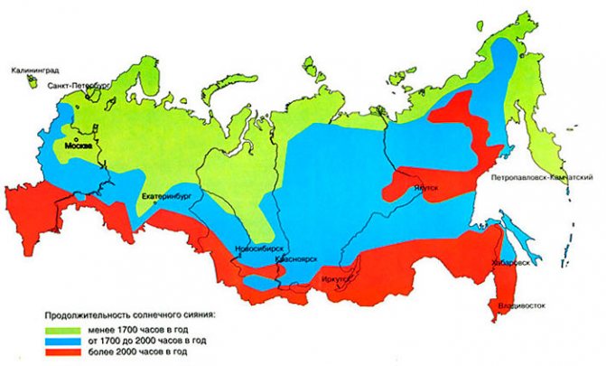
insolation map of russia
We calculate the absorption area for one tube:
15 pipes = 2.35 square meters; 1 tube = 2.35 / 15 = 0.15 sq.
Now that we know the area that is absorbed by one tube, we determine the number of tubes, which is 1 square meter. collector surface: 1 / 0.15 = 6.66. In other words, 7 collector tubes are required per meter of absorption surface.
Next, we calculate the thermal power of one collector tube. This will make it possible to calculate the number of tubes required to obtain sufficient heat energy for periods of one day and one year:
The received power per day is calculated as follows: 0.15 (S absorption of 1 tube) x 1173.7 (insolation value in the Moscow region) x 0.67 (solar collector efficiency) = 117.95 kW * h / m. sq..
To calculate the annual efficiency of one tube in the selected region, the annual insolation data should be used in the formula for calculating the daily capacity. In other words, in place of 1173, 7 it is necessary to put regional values of insolation.
The power generated by one tube in Moscow ranges from 117.95 (using an efficiency of 67%) to 140 kW * hour / sq. M. (when using an efficiency of 80%).
On average, one vacuum tube of the heat collector generates 0.325 kW * hour per day.
In the sunniest months (June, July) one tube will produce 0.545 kWh.
The operation of a solar collector without light is impossible, for this reason, these indicators should be used when calculating daylight hours.
How much electricity can be saved in Moscow using one square meter? collector (as we found out, these are 7 vacuum tubes)?
The annual energy savings will be:
117.95 kW * hour / m2 * 7 = 825.6 kW * hour / sq. M.
The solar collector will generate the highest capacity in the summer months. For example, in June when using 1 sq. M. collector power generation will be about 115-117 kW * hour / sq. m.
In other words, the energy benefit when using a solar collector with 15 vacuum tubes, where S = 2.35 sq.m. for the period from March to August with the total value of insolation for the entire specified period of 874.2 kW * hour / sq. m. will be: 874.2 * 2.35 * 0.67 = 1376 kW, that is, almost 1.4 Megawatts. energy, which is approximately 8 kW per day.
Let us recall the statistical information given in the first part of the article - a household uses from 2 to 4 kW of energy when one person consumes hot water every day. These indicators imply the use of a manifold for heating hot water and, in particular, such needs as taking a shower, washing dishes, etc.
Calculations of the solar collector, consisting of 15 vacuum tubes, allow us to conclude that in the garden season this device will be enough to provide hot water for a family of three. As a result, taking into account all unfavorable circumstances, such as cloudy or rainy weather, it is possible to save very good money on the electricity used to heat the water.
If we talk about optimal conditions (sunny weather and no rain), then in this case, the production of thermal energy by a solar collector will generally avoid the need to pay for electricity.