Calculation of the heat exchanger currently takes no more than five minutes. Any organization that manufactures and sells such equipment, as a rule, provides everyone with its own selection program. You can download it for free from the company's website, or their technician will come to your office and install it for free. However, how correct is the result of such calculations, is it possible to trust it and is the manufacturer not cunning when fighting in a tender with its competitors? Checking an electronic calculator requires knowledge or at least an understanding of the calculation methodology for modern heat exchangers. Let's try to figure out the details.
What is a heat exchanger
Before calculating the heat exchanger, let's remember, what kind of device is it? A heat and mass exchange apparatus (aka a heat exchanger, aka a heat exchanger, or TOA) is a device for transferring heat from one heat carrier to another. In the process of changing the temperatures of the coolants, their densities and, accordingly, the mass indicators of substances also change. That is why such processes are called heat and mass transfer.
Basic concepts of heat transfer for calculation
Heat exchangers are calculated using basic information on heat exchange laws.
In this article, we will look at some of the concepts used in such calculations.
- Specific heat is the amount of heat energy required to heat 1 kilogram of a substance per 1 degree Celsius. Based on the information on the heat capacity, it is shown how much heat is accumulated. For calculations of heat energy, the average value of the heat capacity is taken in a certain range of temperature indicators.
- The amount of heat energy required to heat 1 kg of a substance from zero to the required temperature is called specific enthalpy.
- Specific heat of chemical transformations is the amount of heat energy released in the process of chemical transformation of any unit of weight of a substance.
- Specific heat of phase transformations determines the amount of thermal energy absorbed or released during the transformation of any unit of mass of a substance from solid to liquid, from liquid to gaseous state of aggregation, etc.
An online calculator for calculating a heat exchanger from will help you get a solution in 15 minutes. Or you can use the theory for a plate-type heat exchanger, which is outlined below in this article, and make the necessary calculations yourself.
Types of heat transfer
Now let's talk about the types of heat transfer - there are only three of them. Radiation - the transfer of heat through radiation. As an example, you can think of sunbathing on the beach on a warm summer day. And such heat exchangers can even be found on the market (tube air heaters). However, most often for heating living quarters, rooms in an apartment, we buy oil or electric radiators. This is an example of another type of heat transfer - convection. Convection can be natural, forced (exhaust hood, and there is a recuperator in the box) or mechanically induced (with a fan, for example). The latter type is much more efficient.
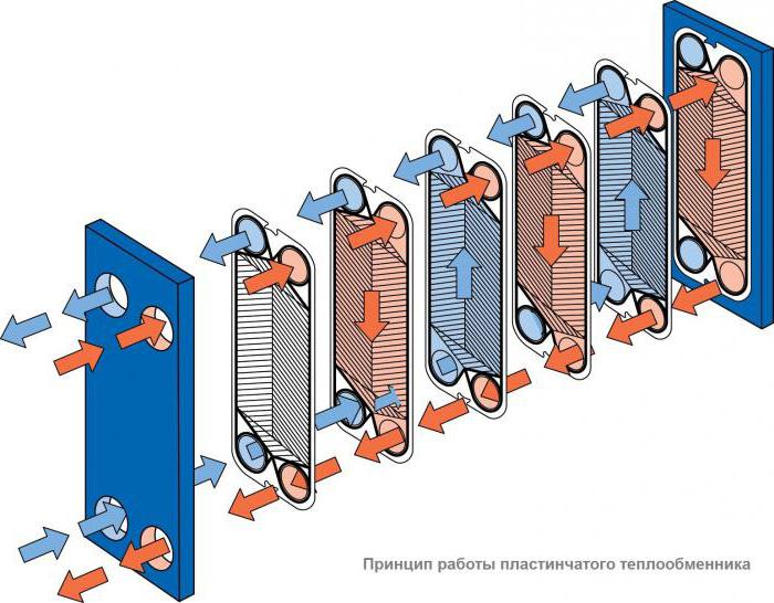
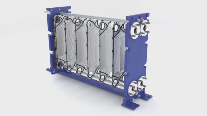
However, the most efficient way of transferring heat is thermal conductivity, or, as it is also called, conduction (from the English conduction - "conduction"). Any engineer who is going to carry out a thermal calculation of a heat exchanger, first of all, thinks about choosing efficient equipment in the smallest possible dimensions.And this is achieved precisely due to thermal conductivity. An example of this is the most efficient TOA today - plate heat exchangers. Plate TOA, by definition, is a heat exchanger that transfers heat from one coolant to another through the wall separating them. The maximum possible contact area between two media, together with correctly selected materials, the profile of the plates and their thickness, allows you to minimize the size of the selected equipment while maintaining the original technical characteristics required in the technological process.
Heat exchanger types
Before calculating the heat exchanger, they are determined with its type. All TOA can be divided into two large groups: recuperative and regenerative heat exchangers. The main difference between them is as follows: in recuperative TOA, heat exchange occurs through a wall separating two coolants, and in regenerative TOA, the two media have direct contact with each other, often mixing and requiring subsequent separation in special separators. Regenerative heat exchangers are divided into mixing and heat exchangers with packing (stationary, falling or intermediate). Roughly speaking, a bucket of hot water exposed to frost or a glass of hot tea placed in the refrigerator to cool (never do that!) Is an example of such a mixing TOA. And by pouring tea into a saucer and cooling it in this way, we get an example of a regenerative heat exchanger with a nozzle (the saucer in this example plays the role of a nozzle), which first contacts the ambient air and takes its temperature, and then takes some of the heat from the hot tea poured into it. , seeking to bring both media into thermal equilibrium. However, as we have already found out earlier, it is more efficient to use thermal conductivity to transfer heat from one medium to another, therefore, TOA that are more useful in terms of heat transfer (and widely used) today are, of course, recuperative.
Heat exchanger calculation example
To calculate the required power (Q0), the heat balance formula is used. Here Wed acts as a specific heat capacity (tabular value). To simplify the calculations, you can take the reduced level of heat capacity
It should be borne in mind that in accordance with the formula, regardless of the side on which the calculation is carried out.
Next, you need to find the required surface area based on the basic heat transfer equation, where k is the heat transfer coefficient, and ΔTav log. - average logarithmic temperature head, calculated by the formula:
With an uncertain heat transfer coefficient, a plate-type heat exchanger is calculated using a more complex method. The formula can be used to calculate the Reynolds criterion.
Having found in the table the value of the Prandtl criterion that we need, we can calculate the Nusselt criterion of the formula, where n = 0.3 - when cooling the liquid, n = 0.4 - when heating the liquid.
Further, based on the formula, you can calculate the heat transfer coefficient from any heat carrier to the wall, and in accordance with the formula, determine the heat transfer coefficient substituted into the formula, with which the heat transfer surface area is calculated.
Thermal and structural calculation
Any calculation of a recuperative heat exchanger can be made based on the results of thermal, hydraulic and strength calculations. They are fundamental, mandatory in the design of new equipment and form the basis of the calculation method for subsequent models of the line of the same type of apparatus. The main task of the thermal calculation of TOA is to determine the required area of the heat exchange surface for stable operation of the heat exchanger and maintaining the required parameters of the media at the outlet.Quite often, in such calculations, engineers are given arbitrary values of the mass and size characteristics of the future equipment (material, pipe diameter, plate dimensions, beam geometry, type and material of finning, etc.), therefore, after the thermal one, a constructive calculation of the heat exchanger is usually carried out. Indeed, if at the first stage the engineer calculated the required surface area for a given pipe diameter, for example, 60 mm, and the length of the heat exchanger thus turned out to be about sixty meters, then it is more logical to assume a transition to a multi-pass heat exchanger, or to a shell-and-tube type, or to increase the diameter of the tubes.
Hydraulic calculation
Hydraulic or hydromechanical, as well as aerodynamic calculations are carried out in order to determine and optimize the hydraulic (aerodynamic) pressure losses in the heat exchanger, as well as to calculate the energy costs to overcome them. The calculation of any path, channel or pipe for the passage of the coolant poses a primary task for a person - to intensify the heat transfer process in this area. That is, one medium should transfer, and the other should receive as much heat as possible at the minimum interval of its flow. For this, an additional heat exchange surface is often used, in the form of a developed surface ribbing (to separate the boundary laminar sublayer and enhance flow turbulization). The optimal balance ratio of hydraulic losses, heat exchange surface area, weight and size characteristics and removed heat power is the result of a combination of thermal, hydraulic and constructive calculation of TOA.
Verification calculation
Calculation of the heat exchanger is carried out in the case when it is necessary to lay a margin for power or for the area of the heat exchange surface. The surface is reserved for various reasons and in different situations: if this is required according to the terms of reference, if the manufacturer decides to add an additional margin in order to be sure that such a heat exchanger will go into operation, and to minimize errors made in the calculations. In some cases, redundancy is required to round off the results of design dimensions, in others (evaporators, economizers), a surface margin is specially introduced into the calculation of the heat exchanger's capacity for contamination with compressor oil present in the refrigeration circuit. And the low quality of water must be taken into account. After some time of uninterrupted operation of heat exchangers, especially at high temperatures, scale settles on the heat exchange surface of the apparatus, reducing the heat transfer coefficient and inevitably leading to a parasitic decrease in heat removal. Therefore, a competent engineer, when calculating the water-to-water heat exchanger, pays special attention to additional redundancy of the heat exchange surface. The verification calculation is also carried out in order to see how the selected equipment will work in other, secondary modes. For example, in central air conditioners (air supply units), first and second heating heaters, used in the cold season, are often used in the summer to cool the incoming air by supplying cold water to the tubes of the air heat exchanger. How they will function and what parameters they will give out allows you to evaluate the verification calculation.
Required data
To calculate the heat exchanger, it is necessary to provide the following data:
- inlet and outlet temperatures on both circuits. The greater the difference between them, the smaller the dimensions and price of a suitable heat exchanger;
- the maximum level of pressure and temperature of the working medium. The lower the parameters, the cheaper the unit;
- indicator of the mass flow rate of the coolant in both circuits. Determines the throughput of the units.Water consumption is most often indicated. If you multiply the figures for throughput and density, you get the total mass flow;
- thermal power (load). Determines the amount of heat that the unit gives off. The calculation of the heat load of the heat exchanger is carried out according to the formula P = m × cp × δt, where m means the flow rate of the medium, cp is the specific heat capacity, and δt is the temperature difference at the inlet and outlet of the circuit.
To calculate the heat transfer of the heat exchanger, additional characteristics will need to be taken into account. The type of working medium and its viscosity index determine the material of the heat exchanger. You will need data on the average temperature head (calculated by the formula) and on the level of contamination of the working environment. The latter parameter is rarely taken into account, since it is required only in exceptional cases.
Calculation of the heat exchanger power requires accurate information about the above parameters. Information can be obtained from the TU or the contract from the heat supply organization, as well as the TOR of the engineer.
Research calculations
Research calculations of TOA are carried out on the basis of the obtained results of thermal and verification calculations. As a rule, they are necessary for making the latest amendments to the design of the projected apparatus. They are also carried out in order to correct any equations laid down in the implemented calculation model TOA, obtained empirically (according to experimental data). Performing research calculations involves tens, and sometimes hundreds of calculations according to a special plan developed and implemented in production according to the mathematical theory of experiment planning. According to the results, the influence of various conditions and physical quantities on the performance indicators of TOA is revealed.
Other calculations
When calculating the area of the heat exchanger, do not forget about the resistance of materials. The TOA strength calculations include checking the designed unit for stress, torsion, for applying the maximum permissible operating moments to the parts and assemblies of the future heat exchanger. With minimal dimensions, the product must be durable, stable and guarantee safe operation in various, even the most stressful operating conditions.
Dynamic calculation is carried out in order to determine the various characteristics of the heat exchanger at variable modes of its operation.
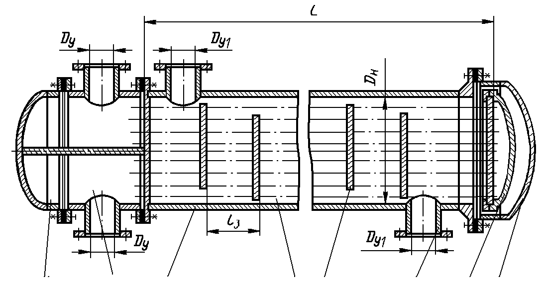
Tube-in-tube heat exchangers
Let's consider the simplest calculation of a pipe-in-pipe heat exchanger. Structurally, this type of TOA is simplified as much as possible. As a rule, a hot coolant is let into the inner pipe of the apparatus to minimize losses, and a cooling coolant is launched into the casing, or into the outer pipe. The task of the engineer in this case is reduced to determining the length of such a heat exchanger based on the calculated area of the heat exchange surface and given diameters.
It should be added here that the concept of an ideal heat exchanger is introduced in thermodynamics, that is, an apparatus of infinite length, where the coolants work in a counterflow, and the temperature difference is fully triggered between them. The tube-in-tube design comes closest to meeting these requirements. And if you run the coolants in a counterflow, then it will be the so-called "real counterflow" (and not crossflow, as in plate TOA). The temperature head is most efficiently triggered with such an organization of movement. However, when calculating a pipe-in-pipe heat exchanger, one should be realistic and not forget about the logistics component, as well as the ease of installation. The length of the eurotruck is 13.5 meters, and not all technical rooms are adapted to the skidding and installation of equipment of this length.
Connection diagrams
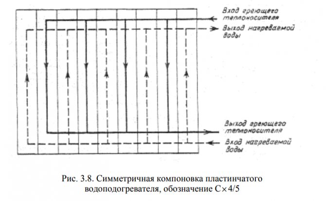
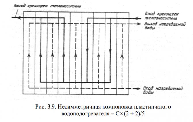
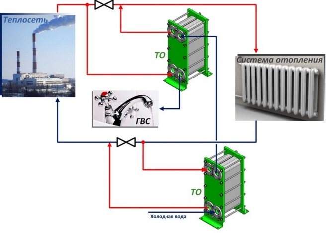
A heat exchanger operating on the water-to-water principle has several different connection schemes, however, the primary type loops are mounted to the distribution pipes of the heating network (it can be private or sold by city services), and the secondary type loops are mounted to the water supply pipeline.
Most often, it depends only on the decisions on the project what type of connection is allowed to be used. Also, the installation scheme and its choice are based on the norms of "Designing of heating units" and in the joint venture standard under the number 41-101-95. If the ratio and difference of the maximum possible water heat flow for hot water supply to the heat flow for heating is determined in the range from ≤0.2 to ≥1, then the basis is the connection diagram in one stage, and if from 0.2≤ to ≤1, then of two degrees ...
Standard
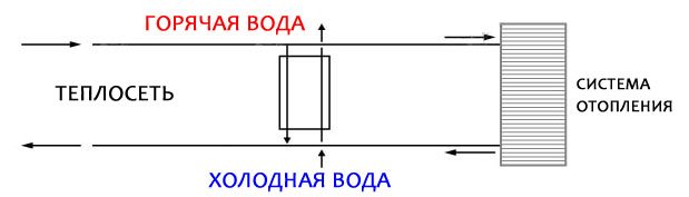
The simplest and most cost effective scheme to implement is parallel. With this scheme, the heat exchangers are mounted in series with respect to the control valves, that is, the shut-off valve, as well as parallel to the entire heating network. In order to achieve maximum heat exchange within the system, high consumption rates of heat carriers are required.
Two-stage scheme
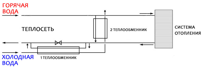
Two-stage mixed system
If you use a two-stage scheme, then with it, water is heated either in a pair of independent devices, or in a monoblock installation. It is important to remember that the installation scheme and its complexity will depend on the overall network configuration. On the other hand, with a two-stage scheme, the level of efficiency of the entire system increases, and the consumption of heat carriers also decreases (up to about 40 percent).
With this scheme, water preparation takes place in two steps. During the first step, thermal energy is applied, heating the water to 40 degrees, and during the second step, the water is heated to 60 degrees.
Serial type connection
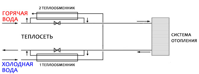
Two-stage sequential scheme
Such a scheme is implemented within the framework of one of the devices for heat exchange of hot water supply, and this type of heat exchanger is much more complicated in design when compared with standard schemes. It will also cost a lot more.
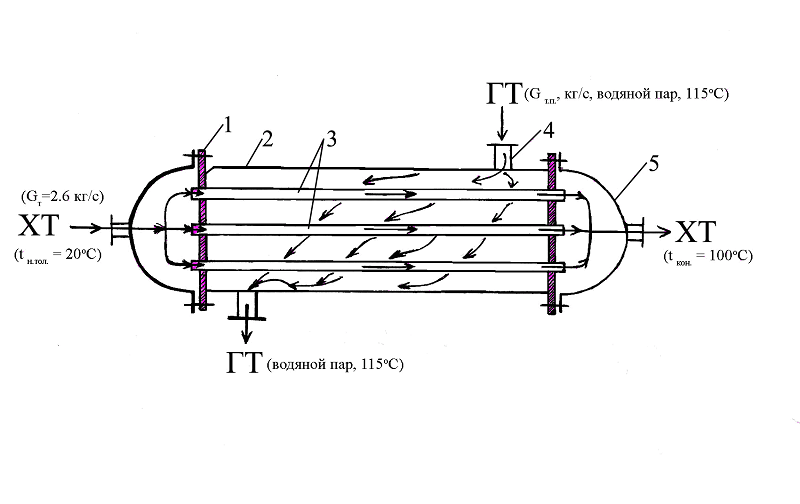
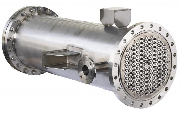
Shell and tube heat exchangers
Therefore, very often the calculation of such an apparatus smoothly flows into the calculation of a shell-and-tube heat exchanger. This is an apparatus in which a bundle of pipes is located in a single casing (casing), washed by various coolants, depending on the purpose of the equipment. In condensers, for example, the refrigerant is run into the jacket and the water into the pipes. With this method of moving media, it is more convenient and more effective to control the operation of the apparatus. In evaporators, on the contrary, the refrigerant boils in the tubes, and at the same time they are washed by the cooled liquid (water, brines, glycols, etc.). Therefore, the calculation of a shell-and-tube heat exchanger is reduced to minimizing the size of the equipment. While playing with the diameter of the casing, the diameter and number of inner pipes and the length of the apparatus, the engineer reaches the calculated value of the area of the heat exchange surface.
Determination of the heat transfer coefficient
For preliminary calculations of heat exchange equipment and various kinds of checks, approximate values of the coefficients are used, standardized for certain categories:
- heat transfer coefficients for the condensation of water vapor - from 4000 to 15000 W / (m2K);
- heat transfer coefficients for water moving through pipes - from 1200 to 5800 W / (m2K);
- heat transfer coefficients from vaporous condensate to water - from 800 to 3500 W / (m2K).
The exact calculation of the heat transfer coefficient (K) is carried out according to the following formula:
In this formula:
- α1 is the heat transfer coefficient for the heating medium (expressed in W / (m2K));
- α2 is the heat transfer coefficient for the heated heat carrier (expressed in W / (m2K));
- δst - parameter of pipe wall thickness (expressed in meters);
- λst - coefficient of thermal conductivity of the material used for the pipe (expressed in W / (m * K)).
Such a formula gives an “ideal” result, which usually does not correspond 100% to the real state of affairs. Therefore, another parameter is added to the formula - Rzag.
This is an indicator of the thermal resistance of various contaminants that form on the heating surfaces of the pipe (i.e. ordinary scale, etc.)
The formula for the pollution indicator looks like this:
R = δ1 / λ1 + δ2 / λ2
In this formula:
- δ1 is the thickness of the sediment layer on the inner side of the pipe (in meters);
- δ2 is the thickness of the sediment layer on the outside of the pipe (in meters);
- λ1 and λ2 are the values of the thermal conductivity coefficients for the corresponding layers of pollution (expressed in W / (m * K)).
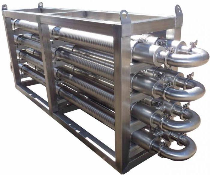
Air heat exchangers
One of the most common heat exchangers today is the finned tubular heat exchangers. They are also called coils. Wherever they are not installed, starting from fan coil units (from the English fan + coil, ie "fan" + "coil") in the internal blocks of split systems and ending with giant flue gas recuperators (heat extraction from hot flue gas and transfer it for heating needs) in boiler plants at CHP. That is why the design of a coil heat exchanger depends on the application where the heat exchanger will go into operation. Industrial air coolers (VOPs), installed in blast freezing chambers of meat, in freezers of low temperatures and at other objects of food refrigeration, require certain design features in their performance. The distance between the lamellas (fins) should be as large as possible to increase the continuous operation time between defrost cycles. Evaporators for data centers (data processing centers), on the contrary, are made as compact as possible, clamping the spacing to a minimum. Such heat exchangers operate in "clean zones" surrounded by fine filters (up to the HEPA class), therefore, such a calculation of the tubular heat exchanger is carried out with an emphasis on minimizing the size.
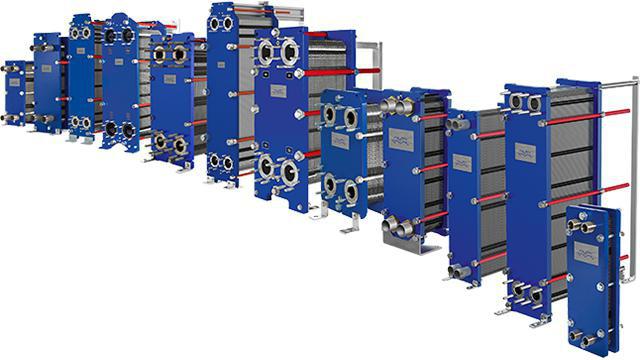
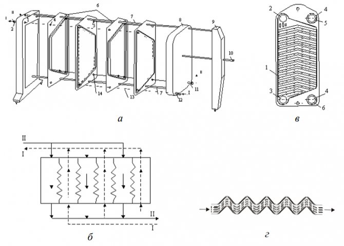
Plate heat exchangers
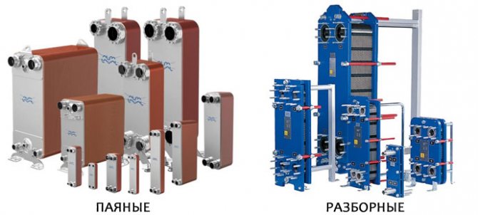
Currently, plate heat exchangers are in stable demand. According to their design, they are completely collapsible and semi-welded, copper-brazed and nickel-brazed, welded and brazed by the diffusion method (without solder). The thermal design of a plate heat exchanger is flexible enough and not particularly difficult for an engineer. In the selection process, you can play with the type of plates, the punching depth of the channels, the type of ribbing, the thickness of steel, different materials, and most importantly - numerous standard-size models of devices of different dimensions. Such heat exchangers are low and wide (for steam heating of water) or high and narrow (separating heat exchangers for air conditioning systems). They are often used for phase change media, that is, as condensers, evaporators, desuperheaters, pre-condensers, etc. It is a little more difficult to carry out the thermal calculation of a heat exchanger operating according to a two-phase scheme than a liquid-liquid heat exchanger, but for an experienced engineer, this task is solvable and not particularly difficult. To facilitate such calculations, modern designers use engineering computer bases, where you can find a lot of necessary information, including diagrams of the state of any refrigerant in any scan, for example, the CoolPack program.

Calculation of a plate heat exchanger - how to determine the parameters correctly?
General principles of the design of heat supply schemes
The heat supply system is a system for transporting heat energy (in the form of heated water or steam) from a heat source to its consumer.
The heat supply system basically consists of three parts: a heat source, a heat consumer, a heat network - which serves to transport heat from a source to a consumer.
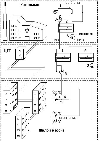
- Steam boiler at a CHP or boiler room.
- Network heat exchanger.
- Circulation pump.
- Heat exchanger of the hot water supply system.
- Heating system heat exchanger.
Role of circuit elements:
- boiler unit - a heat source, transfer of the heat of combustion of the fuel to the coolant;
- pumping equipment - creating a circulation of the coolant;
- supply pipeline - supply of heated coolant from the source to the consumer;
- return pipeline - return of the cooled heat carrier to the source from the consumer;
- heat exchange equipment - conversion of heat energy.
Temperature charts
In our country, high-quality regulation of heat supply to consumers has been adopted. That is, without changing the flow rate of the coolant through the heat-consuming system, the temperature difference at the inlet and outlet of the system changes.
This is achieved by changing the temperature in the flow pipe depending on the outside temperature. The lower the outdoor temperature, the higher the flow temperature. Accordingly, the temperature of the return pipe also changes according to this relationship. And all systems that consume heat are designed with these requirements in mind.
The graphs of the temperature dependence of the coolant in the supply and return pipelines are called the temperature graph of the heat supply system.
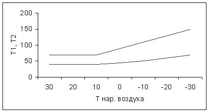
The temperature schedule is set by the heat supply source depending on its capacity, the requirements of heating networks, and the requirements of consumers. Temperature curves are named according to the maximum temperatures in the supply and return pipelines: 150/70, 95/70 ...
Cutting off the graph in the upper part - when the boiler room does not have enough capacity.
Cutting off the graph in the lower part - to ensure the operability of the DHW systems.
The heating systems operate mainly according to the 95/70 schedule to ensure an average temperature in the heater of 82.5 ° C at -30 ° C.
If the required temperature in the supply pipe is provided by the heat source, then the required temperature in the return pipe is provided by the heat consumer with his heat-consuming system. If there is an overestimation of the temperature of the return water from the consumer, then this means the unsatisfactory operation of his system and entails fines, since it leads to a deterioration in the operation of the heat source. At the same time, its efficiency decreases. Therefore, there are special control organizations that monitor that the heat-consuming systems of consumers give out the return water temperature according to the temperature schedule or lower. However, in some cases, such an overestimate is allowed, for example. when installing heating heat exchangers.
The 150/70 schedule will allow the transfer of heat from a heat source with lower heat carrier consumption, however, a heat carrier with a temperature above 105 ° C cannot be supplied to house heating systems. Therefore, the schedule is lowered, for example, by 95/70. Lowering is carried out by installing a heat exchanger or mixing return water into the supply pipeline.
Heating network hydraulics
The circulation of water in heat supply systems is carried out by network pumps at boiler houses and heating points. Since the length of the lines is quite large, the pressure difference in the supply and return pipelines, which the pump creates, decreases with distance from the pump.
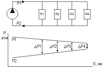
It can be seen from the figure that the most remote consumer has the smallest available pressure drop. Ie.for the normal operation of its heat-consuming systems, it is necessary that they have the lowest hydraulic resistance to ensure the required water flow through them.
Calculation of plate heat exchangers for heating systems
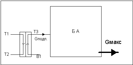
Heating water can be prepared by heating in a heat exchanger.
When calculation of a plate heat exchanger to obtain heating water, the initial data are taken for the coldest period, that is, when the highest temperatures are required and, accordingly, the highest heat consumption. This is the worst case for a heat exchanger designed for heating.
The peculiarity of calculating a heat exchanger for a heating system is an overestimated return water temperature on the heating side. This is allowed on purpose, since any surface heat exchanger, in principle, cannot cool the return water to the temperature of the graph, if water with the temperature of the graph enters the inlet to the heat exchanger on the heated side. Usually a difference of 5-15 ° C is allowed.
Calculation of plate heat exchangers for DHW systems
When calculation of plate heat exchangers for hot water systems The initial data are taken for the transition period, that is, when the temperature of the supply coolant is low (usually 70 ° C), the cold water has the lowest temperature (2-5 ° C) and the heating system is still working - these are May-September months. This is the worst mode for the DHW heat exchanger.
The design load for DHW systems is determined based on the availability at the facility where the heat exchangers of the storage tanks are installed.
In the absence of tanks, plate heat exchangers are designed for maximum load. That is, heat exchangers must provide heating of water even at maximum water intake.
With storage tanks, plate heat exchangers are designed for an hourly average load. The accumulator tanks are constantly replenished to compensate for the peak draw-off. The heat exchangers should only provide replenishment of the tanks.
The ratio of the maximum and average hourly load in some cases reaches 4-5 times.
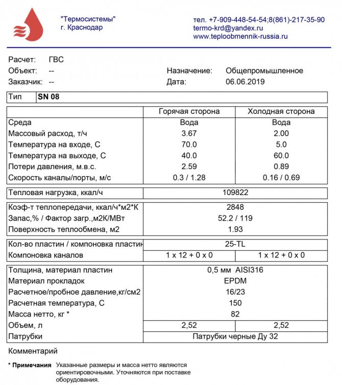
Please note that it is convenient to calculate plate heat exchangers in our own calculation program "Ridan".