Here you will find out:
- When you need a controller
- Solar controller functions
- How the Battery Charge Controller Works
- Device characteristics
- Types
- Selection options
- Ways to connect controllers
- Homemade controller: features, accessories
- How can I replace some components
- Principle of operation
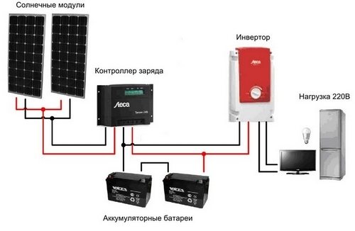
The solar battery charge controller is a mandatory element of the power system on solar panels, except for the batteries and the panels themselves. What is he responsible for and how to make it yourself?
When you need a controller
Solar energy is still limited (at the household level) to the creation of photovoltaic panels of relatively low power. But regardless of the design of the solar-to-current photoelectric converter, this device is equipped with a module called a solar battery charge controller.
Indeed, the solar light photosynthesis setup includes a rechargeable battery, which stores the energy received from the solar panel. It is this secondary energy source that is primarily serviced by the controller.
Next, we will understand the device and the principles of operation of this device, and also talk about how to connect it.
When the battery is at its maximum charge, the controller will regulate the current supply to it, reducing it to the required amount of compensation for the self-discharge of the device. If the battery is completely discharged, the controller will disconnect any incoming load to the device.
The need for this device can be boiled down to the following points:
- Multi-stage battery charging;
- Adjustment of turning on / off the battery when charging / discharging the device;
- Battery connection at maximum charge;
- Connecting charging from photocells in automatic mode.
The battery charge controller for solar devices is important because performing all of its functions in good working order greatly increases the life of the built-in battery.
What are battery charge controllers for?
If the battery is connected directly to the terminals of the solar panels, then it will be charged continuously. Ultimately, a fully charged battery will continue to receive current, causing the voltage to rise by several volts. As a result, the battery is recharged, the temperature of the electrolyte rises, and this temperature reaches such values that the electrolyte boils, there is a sharp release of vapors from the battery cans. As a result, the electrolyte can completely evaporate and the cans dry out. Naturally, this does not add "health" to the battery and dramatically reduces the resource of its performance.
Controller in the solar battery charging system
Here, in order to prevent such phenomena, in order to optimize the charging / discharging processes, controllers are needed.
Solar controller functions
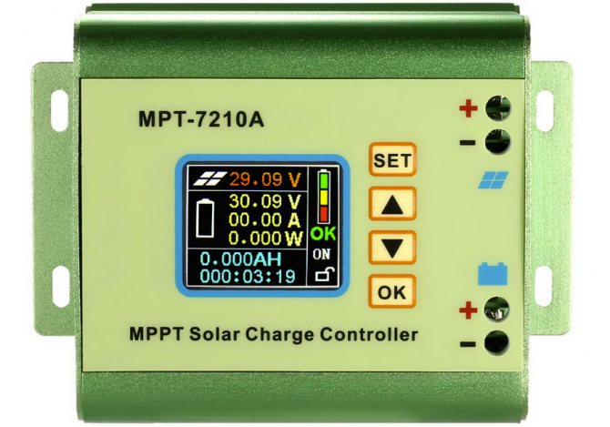
The electronic module, called the solar battery controller, is designed to perform a variety of monitoring functions during the charging / discharging process of the solar battery.
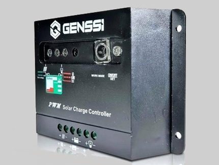
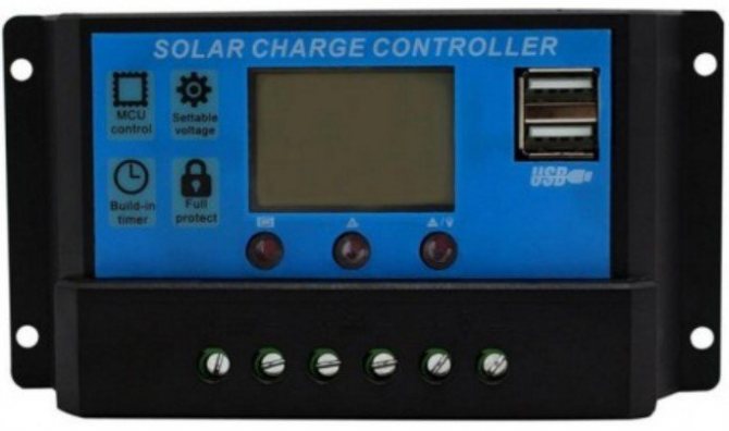
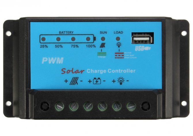
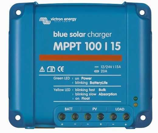
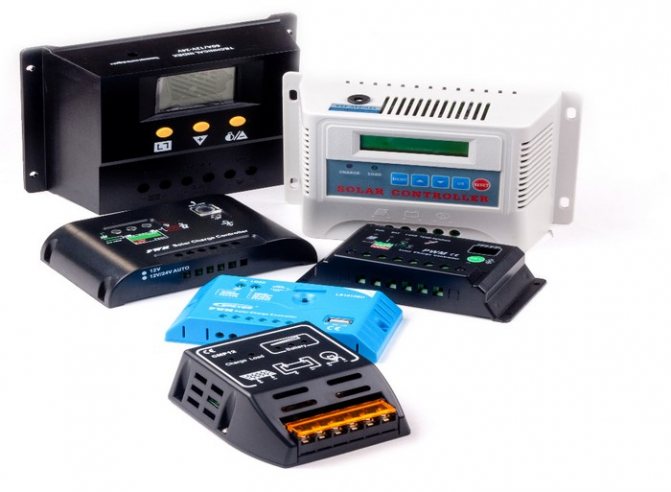
This looks like one of the many existing models of charge controllers for solar panels. This module belongs to the development of the PWM type
When sunlight falls on the surface of a solar panel installed, for example, on the roof of a house, the photocells of the device convert this light into electric current.
The resulting energy, in fact, could be fed directly to the storage battery.However, the process of charging / discharging the battery has its own subtleties (certain levels of currents and voltages). If we neglect these subtleties, the battery will simply fail in a short period of time.
In order not to have such sad consequences, a module called a charge controller for a solar battery is designed.
In addition to monitoring the battery charge level, the module also monitors energy consumption. Depending on the degree of discharge, the battery charge controller circuit from the solar battery regulates and sets the level of current required for the initial and subsequent charging.
Depending on the capacity of the solar battery charge controller, the designs of these devices can have very different configurations.
In general, in simple terms, the module provides a carefree "life" for the battery, which periodically accumulates and releases energy to consumer devices.
Why charge control and how does a solar charge controller work?
Main reasons:
- It will allow the battery to work longer! Overcharging can trigger an explosion.
- Each battery operates at a specific voltage. The controller allows you to select the desired U.
Also, the charge controller disconnects the battery from consumption devices if it is very low. In addition, it disconnects the battery from the solar cell if it is fully charged.
Thus, insurance occurs and the operation of the system becomes safer.
The principle of operation is extremely simple. The device helps maintain balance and does not allow the voltage to fall or rise too much.
Types of controllers for solar battery charging
- Homemade.
- MRRT.
- On / Of.
- Hybrids.
- PWM types.
Below we briefly describe these options for lithium devices and other batteries
DIY controllers
When you have experience and skills in electronics, this device can be made independently. But such a device is unlikely to have high efficiency. A homemade device is most likely suitable if your station has low power.
To build this charging device, you will have to find its circuit. But keep in mind that the margin of error must be 0.1.
Here is a simple diagram.
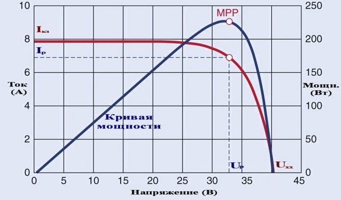
MRRT
Capable of tracking the highest charging power limit. Inside the software there is an algorithm that allows you to monitor the voltage and current levels. It finds a certain balance in which the entire installation will operate at maximum efficiency.
The mppt device is considered one of the best and most advanced today. Unlike PMW, it increases system efficiency by 35%. Such a device is suitable when you have a lot of solar panels.
Instrument type ON / OF
It is the simplest one on sale. It doesn't have as many features as the others. The device turns off recharging the battery as soon as the voltage rises to the maximum.
Unfortunately, this type of solar charge controller is unable to charge up to 100%. As soon as the current jumps to the maximum, a shutdown occurs. As a result, an incomplete charge reduces its useful life.
Hybrids
The data is applied to the instrument when there are two types of power sources, for example, sun and wind. Their design is based on PWM and MPRT. Its main difference from similar devices is the characteristics of the current and voltage.
Its purpose: to equalize the load going to the battery. This is due to the uneven flow of current from the wind of the generators. Because of this, the life of the energy storage can be significantly reduced.
PWM or PWM
The work is based on pulse width modulation of the current. Solves the problem of incomplete charging. It lowers the current and thus brings the recharge up to 100%.
As a result of pwm operation, there is no overheating of the battery.As a result, this solar control unit is considered to be very efficient.
How the Battery Charge Controller Works
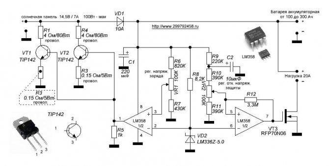
In the absence of sunlight on the photocells of the structure, it is in sleep mode. After the rays appear on the elements, the controller is still in sleep mode. It turns on only if the stored energy from the sun reaches 10 volts in electrical equivalent.
As soon as the voltage reaches this figure, the device turns on and starts supplying current to the battery through the Schottky diode. The battery charging process in this mode will continue until the voltage received by the controller reaches 14 V. If this happens, then some changes will occur in the controller circuit for a 35 watt solar battery or any other. The amplifier will open access to the MOSFET, and the other two, weaker ones, will be closed.
This will stop charging the battery. As soon as the voltage drops, the circuit will return to its original position and charging will continue. The time allotted for this operation to the controller is about 3 seconds.
Some features of solar charge controllers
In conclusion, I need to say about a few more features of charge controllers. In modern systems, they have a number of protections to improve operational reliability. In such devices, the following types of protection can be implemented:
- Against wrong polarity connection;
- From short circuits in the load and at the input;
- From lightning;
- Overheating;
- From input overvoltages;
- From the discharge of the battery at night.
In addition, all kinds of electronic fuses are installed in them. To facilitate the operation of solar systems, charge controllers have information displays. They display information about the state of the battery and the system as a whole. There may be data such as:
- State of charge, battery voltage;
- Current given off by photocells;
- Battery charge and load current;
- Ampere-hours stored and donated.
The display can also show a message about a low charge, a warning about a power failure to the load.
Some models of solar controllers have timers for activating night mode. There are sophisticated devices that control the operation of two independent batteries. They usually have the prefix Duo in their name. It is also worth noting models that are able to dump excess energy on heating elements.
Models with an interface for connecting to a computer are interesting. In this way, the functionality of monitoring and controlling the solar system can be significantly expanded. If the article turned out to be useful to you, spread the link to it on social networks. By doing this, you will help the development of the site. Vote in the poll below and rate the material! Leave corrections and additions to the article in the comments.
Device characteristics
Low power consumption when idle. The circuit was designed for small to medium sized lead acid batteries and draws a low current (5mA) when idle. This extends the battery life.
Readily available components. The device uses conventional components (not SMD) that can be easily found in stores. Nothing needs to be flashed, the only thing you need is a voltmeter and an adjustable power supply to tune the circuit.
The latest version of the device. This is the third version of the device, so most of the errors and shortcomings that were present in the previous versions of the charger have been corrected.
Voltage regulation. The device uses a parallel voltage regulator so that the battery voltage does not exceed the norm, usually 13.8 Volts.
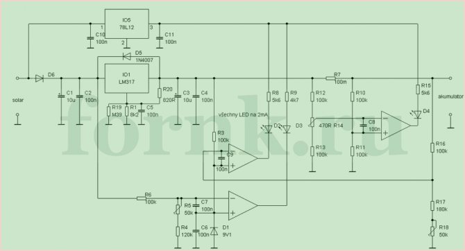
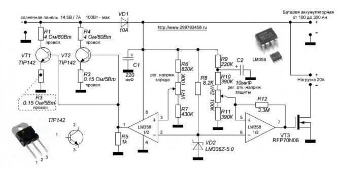
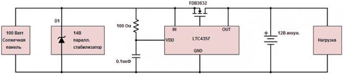
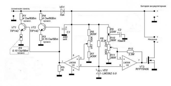
Undervoltage protection. Most solar chargers use a Schottky diode to protect against battery leakage to the solar panel.A shunt voltage regulator is used when the battery is fully charged. One of the problems with this approach is diode losses and, as a consequence, its heating. For example, a solar panel of 100 watts, 12V, supplies 8A to the battery, the voltage drop across the Schottky diode will be 0.4V, i.e. the power dissipation is about 3.2 watts. This is, firstly, losses, and secondly, the diode will need a radiator to remove heat. The problem is that it will not work to reduce the voltage drop, several diodes connected in parallel will reduce the current, but the voltage drop will remain that way. In the diagram below, instead of conventional diodes, mosfets are used, therefore power is lost only for active resistance (resistive losses).
For comparison, in a 100 W panel when using IRFZ48 (KP741A) mosfets, the power loss is only 0.5 W (at Q2). This means less heat and more energy for the batteries. Another important point is that mosfets have a positive temperature coefficient and can be connected in parallel to reduce on resistance.
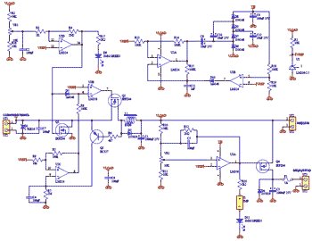
The above diagram uses a couple of non-standard solutions.
Charging. No diode is used between the solar panel and the load, instead there is a Q2 mosfet. A diode in the mosfet allows current to flow from the panel to the load. If a significant voltage appears on Q2, then the transistor Q3 opens, the capacitor C4 is charged, which forces the op-amp U2c and U3b to open the mosfet of Q2. Now, the voltage drop is calculated according to Ohm's law, i.e. I * R, and it is much less than if there was a diode there. Capacitor C4 is periodically discharged through resistor R7 and Q2 closes. If a current flows from the panel, then the self-induction EMF of the inductor L1 immediately forces Q3 to open. This happens very often (many times per second). In the case when the current goes to the solar panel, Q2 closes, but Q3 does not open, because diode D2 limits the self-induction EMF of the choke L1. Diode D2 can be rated for 1A current, but during testing it turned out that such a current rarely occurs.
The VR1 trimmer sets the maximum voltage. When the voltage exceeds 13.8V, the operational amplifier U2d opens the mosfet of Q1 and the output from the panel is "short-circuited" to ground. In addition, the U3b opamp turns off Q2 and so on. the panel is disconnected from the load. This is necessary because Q1, in addition to the solar panel, "short-circuits" the load and the battery.
Management of N-channel mosfets. The mosfets Q2 and Q4 require more voltage to drive than those used in the circuit. To do this, the op-amp U2 with a strapping of diodes and capacitors creates an increased voltage VH. This voltage is used to power U3, the output of which will be overvoltage. A bunch of U2b and D10 ensure the stability of the output voltage at 24 volts. With this voltage, there will be a voltage of at least 10V through the gate-source of the transistor, so the heat generation will be small. Usually, N-channel mosfets have much lower impedance than P-channel ones, which is why they were used in this circuit.
Undervoltage protection. Mosfet Q4, U3a opamp with external strapping of resistors and capacitors, are designed for undervoltage protection. Here Q4 is used non-standard. The mosfet diode provides a constant flow of current into the battery. When the voltage is above the specified minimum, the mosfet is open, allowing a small voltage drop when charging the battery, but more importantly, it allows current from the battery to flow to the load if the solar cell cannot provide sufficient output power. A fuse protects against short-circuits on the load side.
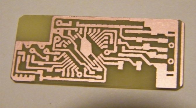
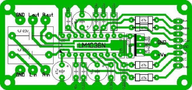
Below are pictures of the arrangement of elements and printed circuit boards.
Setting up the device. During normal use of the device, jumper J1 must not be inserted! The D11 LED is used for setting. To configure the device, connect an adjustable power supply to the “load” terminals.
Setting undervoltage protection Insert jumper J1. In the power supply, set the output voltage to 10.5V. Turn trimmer VR2 counterclockwise until LED D11 lights up. Turn VR2 slightly clockwise until the LED turns off. Remove jumper J1.
Setting the maximum voltage In the power supply, set the output voltage to 13.8V. Turn trimmer VR1 clockwise until LED D9 turns off. Turn VR1 slowly counterclockwise until LED D9 lights up.
The controller is configured. Don't forget to remove jumper J1!
If the capacity of the entire system is small, then the mosfets can be replaced with cheaper IRFZ34. And if the system is more powerful, then the mosfets can be replaced with more powerful IRFZ48.
Homemade solar panel controller
- home
- > My little experience
The controller is very simple and consists of only four parts.
This is a powerful transistor (I am using an IRFZ44N that can handle up to 49Amps).
Automotive relay-regulator with plus control (VAZ "classic").
Resistor 120kOhm.
The diode is more powerful to hold the current given off by the solar panel (for example, from a car diode bridge).
The principle of operation is also very simple. I am writing for people who do not understand electronics at all, since I myself do not understand anything about it.
The relay regulator is connected to the battery, minus to the aluminum base (31k), plus to (15k), from the contact (68k) the wire is connected through a resistor to the gate of the transistor. The transistor has three legs, the first is the gate, the second is the drain, the third is the source. The minus of the solar panel is connected to the source, and the plus to the battery, from the drain of the transistor minus the solar panel goes to the battery.
When the relay-regulator is connected and working, the positive signal from (68k) unlocks the gate and the current from the solar panel flows through the source-drain into the battery, and when the voltage on the battery exceeds 14 volts, the relay-regulator turns off the plus and the gate of the transistor is discharged through the resistor it closes by minus, thereby breaking the minus contact of the solar panel, and it turns off. And when the voltage drops a little, the relay-regulator will again give a plus to the gate, the transistor will open and again the current from the panel will flow into the battery. A diode on the positive wire of the SB is needed so that the battery does not discharge at night, since without light the solar panel itself consumes electricity.
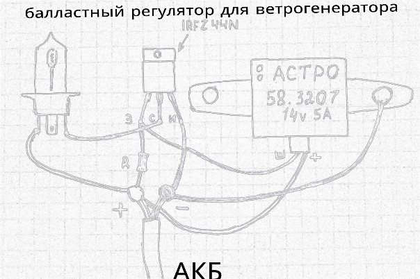
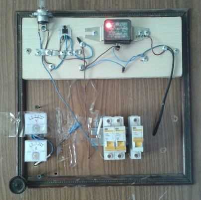
Below is a visual illustration of the connection of controller elements.
I'm not good at electronics and maybe there are some flaws in my circuit, but it works without any settings and works right away, and does what factory controllers for solar panels do, and the cost price is only about 200 rubles and an hour of work.
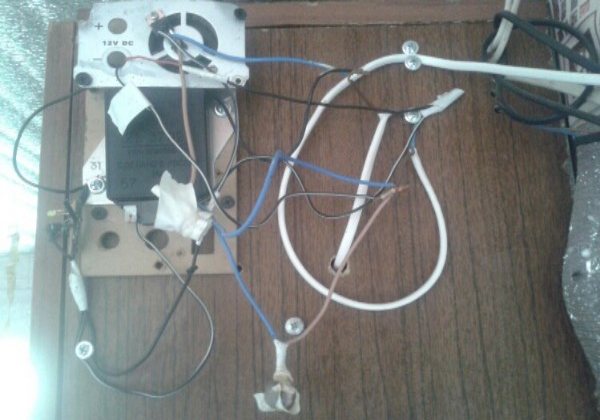
Below is an incomprehensible photo of this controller, just like that, all the details of the controller are fixed on the case of the box. The transistor heats up a little and I fixed it to a small fan. In parallel with the resistor, I put a small LED, which shows the operation of the controller. When the SB is on, when it is not, it means the battery is charged, and when the battery flashes quickly, the battery is almost charged and just recharges.
This controller has been working for more than six months and during this time there are no problems, I connected everything, now I do not follow the battery, everything works by itself. This is my second controller, the first I assembled for wind generators as a ballast regulator, see about it in the previous articles in the section my homemade products.
Attention - the controller is not fully operational. After some time of work, it became clear that the transistor in this circuit does not completely close, and the current continues to flow into the battery anyway, even when 14 volts are exceeded
I apologize for the inoperative circuit, I myself used it for a long time and thought that everything worked, but it turns out not, and even after a full charge, current still flows into the battery. The transistor closes only halfway when it reaches 14 volts. I will not remove the circuit yet, as time and desire appear, I will finish this controller and lay out the working circuit.
And now I have a ballast regulator as a controller, which has been working perfectly for a long time. As soon as the voltage exceeds 14 volts, the transistor opens and turns on the light bulb, which burns all excess energy. At the same time, there are now two solar panels and a wind turbine on this ballast.
Types
On / Off
This type of device is considered the simplest and cheapest. Its only and main task is to turn off the supply of charge to the battery when the maximum voltage is reached to prevent overheating.
However, this type has a certain disadvantage, which is too early shutdown. After reaching the maximum current, it is necessary to maintain the charging process for another couple of hours, and this controller will immediately turn it off.
As a result, the battery charge will be in the region of 70% of the maximum. This negatively affects the battery.

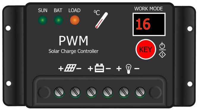
PWM
This type is an advanced On / Off. The upgrade is that it has a built-in pulse width modulation (PWM) system. This function allowed the controller, upon reaching the maximum voltage, not to turn off the current supply, but to reduce its strength.
Because of this, it became possible to almost completely charge the device.
MRRT
This type is considered the most advanced at the present time. The essence of his work is based on the fact that he is able to determine the exact value of the maximum voltage for a given battery. It continuously monitors the current and voltage in the system. Due to the constant receipt of these parameters, the processor is able to maintain the most optimal values of current and voltage, which allows you to create maximum power.
If we compare the controller MPPT and PWN, then the efficiency of the former is higher by about 20-35%.
Controller types
On / Off Controllers
These models are the simplest of the entire class of solar charge controllers.
On / Off charge controller for solar systems
On / Off models are designed to shut off the battery charge when the upper voltage limit is reached. This is usually 14.4 volts. As a result, overheating and overcharging are prevented.
The On / Off controllers will not be able to fully charge the battery. After all, here the shutdown occurs at the moment when the maximum current is reached. And the charging process to full capacity still needs to be maintained for several hours. The charge level at the time of shutdown is somewhere around 70 percent of the nominal capacity. Naturally, this negatively affects the condition of the battery and reduces its service life.
PWM controllers
In search of a solution to incomplete battery charging in a system with On / Off devices, control units have been developed based on the principle of pulse width modulation (PWM for short) of the charging current. The point of operation of such a controller is that it reduces the charging current when the voltage limit is reached. With this approach, the battery charge reaches almost 100 percent. The efficiency of the process is increased by up to 30 percent.
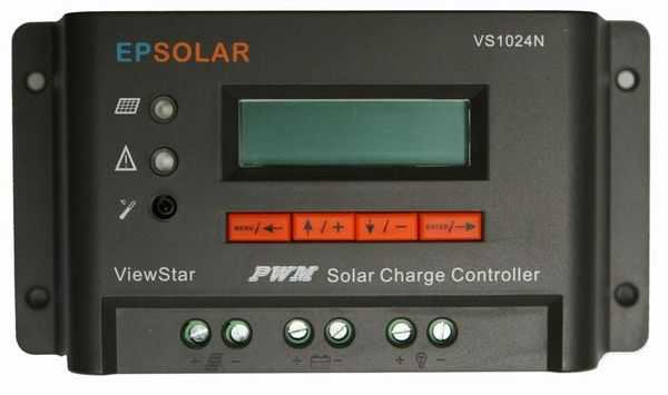
PWM charge controller
There are PWM models that can regulate the current depending on the operating temperature. This has a good effect on the condition of the battery, the heating decreases, the charge is better accepted. The process becomes automatically regulated.
Experts recommend using PWM charge controllers for solar panels in those regions where there is high activity of sunlight.They can often be found in solar systems of low power (less than two kilowatts). As a rule, small capacity rechargeable batteries work in them.
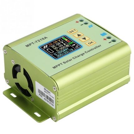
Regulators type MPPT
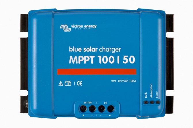
MPPT charge controllers today are the most advanced devices for regulating the process of charging a storage battery in solar systems. These models increase the efficiency of generating electricity from the same solar panels. The principle of operation of MPPT devices is based on determining the point of maximum power value.
MPPT charge controller
The MPPT continuously monitors the current and voltage in the system. Based on this data, the microprocessor calculates the optimum ratio of parameters in order to achieve maximum power output. When adjusting the voltage, even the stage of the charging process is taken into account. MPPT solar controllers even allow you to take a lot of voltage from the modules, then convert it to optimal voltage. Optimal means the one that fully charges the battery.
If we evaluate the work of MPPT in comparison with PWM, then the efficiency of the solar system will increase from 20 to 35 percent. The pluses also include the ability to work with the shading of the solar panel up to 40 percent. Due to the ability to maintain a high voltage value at the output of the controller, small wiring can be used. It is also possible to put solar panels and the unit at a greater distance than in the case of PWM.
Hybrid charge controllers
In some countries, for example, the USA, Germany, Sweden, Denmark, a significant part of the electricity is generated by wind turbines. In some small countries, alternative energy occupies a large share in the energy networks of these states. As part of wind systems, there are also devices for controlling the charging process. If the power plant is a combined version of a wind generator and solar panels, then hybrid controllers are used.
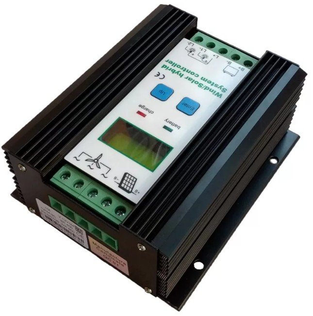
Hybrid controller
These devices can be built with an MPPT or PWM circuit. The main difference is that they use different volt-ampere characteristics. During operation, wind generators produce very uneven electricity production. The result is an uneven load on the batteries and stressful operation. The task of the hybrid controller is to discharge excess energy. For this, as a rule, special heating elements are used.
Homemade controllers
People who understand electrical engineering often build charge controllers for wind turbines and solar panels themselves. The functionality of such models is often inferior in efficiency and feature set to factory devices. However, in small installations, the power of a home-made controller is quite enough.
Homemade solar charge controller
When creating a charge controller with your own hands, you should remember that the total power must satisfy the following condition: 1.2P ≤ I * U. I is the output current of the controller, U is the voltage when the battery is discharged.
There are quite a few homemade controller circuits. You can search for them on the appropriate forums on the net. Here it should be said only about some general requirements for such a device:
- The charging voltage should be 13.8 volts and varies depending on the rated current;
- The voltage at which the charge is turned off (11 volts). This value must be configurable;
- The voltage at which the charge turns on is 12.5 volts.
So, if you decide to assemble a solar system with your own hands, you will have to start making a charge controller. You cannot do without it when operating solar panels and wind turbines.
Selection options
There are only two selection criteria:
- The first and very important point is the incoming voltage. The maximum of this indicator should be higher by about 20% of the open circuit voltage of the solar battery.
- The second criterion is the rated current. If the PWN type is selected, then its rated current must be higher than the short-circuit current of the battery by about 10%. If MPPT is chosen, then its main characteristic is power. This parameter must be greater than the voltage of the entire system multiplied by the rated current of the system. For calculations, the voltage is taken with discharged batteries.
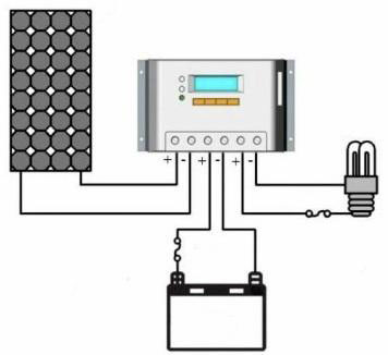
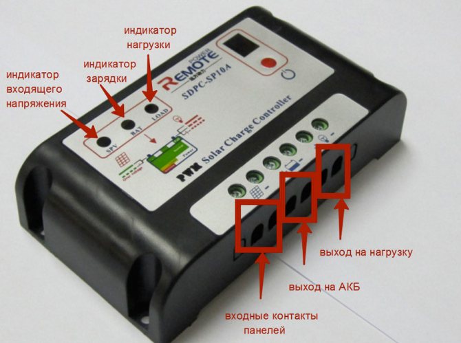
Ways to connect controllers
Considering the topic of connections, it should be noted right away: for the installation of each individual device, a characteristic feature is the work with a specific series of solar panels.
So, for example, if a controller is used that is designed for a maximum input voltage of 100 volts, a series of solar panels should output a voltage no more than this value.
Any solar power plant operates according to the rule of balance between the output and input voltages of the first stage. The upper voltage limit of the controller must match the upper voltage limit of the panel
Before connecting the device, it is necessary to determine the place of its physical installation. According to the rules, the place of installation should be selected in dry, well-ventilated areas. The presence of flammable materials near the device is excluded.
The presence of sources of vibration, heat and humidity in the immediate vicinity of the device is unacceptable. The installation site must be protected from atmospheric precipitation and direct sunlight.
PWM Model Connection Technique
Almost all manufacturers of PWM controllers require an exact sequence of connecting devices.
The technique of connecting PWM controllers with peripheral devices is not particularly difficult. Each board is equipped with labeled terminals. Here you simply need to follow the sequence of actions.
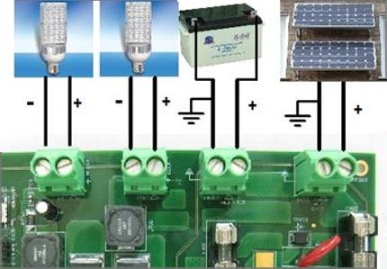
Peripheral devices must be connected in full accordance with the designations of the contact terminals:
- Connect the battery wires to the battery terminals of the device in accordance with the indicated polarity.
- Switch on the protective fuse directly at the point of contact of the positive wire.
- On the contacts of the controller intended for the solar panel, fix the conductors coming out from the solar panels of the panels. Observe polarity.
- Connect a test lamp of the appropriate voltage (usually 12 / 24V) to the load terminals of the device.
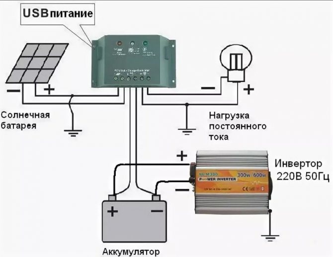
The specified sequence must not be violated. For example, it is strictly forbidden to connect solar panels in the first place when the battery is not connected. By such actions, the user runs the risk of "burning" the device. This material describes in more detail the assembly diagram of solar cells with a battery.
Also, for PWM series controllers, it is unacceptable to connect a voltage inverter to the load terminals of the controller. The inverter should be connected directly to the battery terminals.
Procedure for connecting MPPT devices
The general requirements for physical installation for this type of apparatus do not differ from previous systems. But the technological setup is often somewhat different, since MPPT controllers are often considered more powerful devices.
For controllers designed for high power levels, it is recommended to use cables of large cross-sections, equipped with metal terminators, at the power circuit connections.
For example, for high-power systems, these requirements are complemented by the fact that manufacturers recommend taking a cable for power connection lines designed for a current density of at least 4 A / mm2. That is, for example, for a controller with a current of 60 A, a cable is needed to connect to a battery with a cross section of at least 20 mm2.
The connecting cables must be equipped with copper lugs, tightly crimped with a special tool. The negative terminals of the solar panel and battery must be equipped with fuse and switch adapters.
This approach eliminates energy losses and ensures the safe operation of the installation.
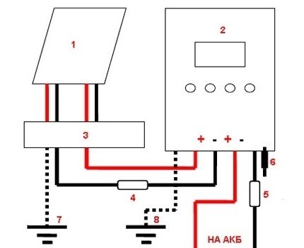
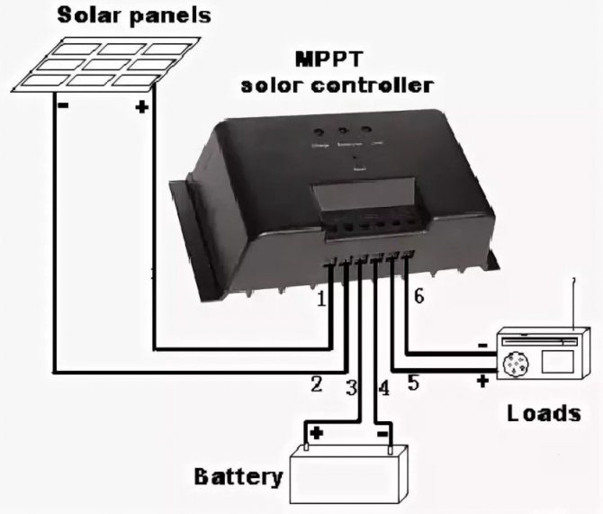
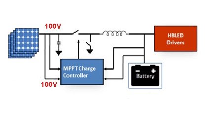
Block diagram for connecting a powerful MPPT controller: 1 - solar panel; 2 - MPPT controller; 3 - terminal block; 4.5 - fuses; 6 - controller power switch; 7.8 - ground bus
Before connecting solar panels to the device, make sure that the voltage at the terminals matches or is less than the voltage that is allowed to be applied to the controller input.
Connecting peripherals to the MTTP device:
- Place the panel and battery switches in the off position.
- Remove the panel and battery protection fuses.
- Connect the cable from the battery terminals to the controller terminals for the battery.
- Connect the solar panel leads with the controller terminals marked with the appropriate sign.
- Connect a cable between the ground terminal and the ground bus.
- Install the temperature sensor on the controller according to the instructions.
After these steps, you must insert the previously removed battery fuse into place and turn the switch to the "on" position. The battery detection signal will appear on the controller screen.
Then, after a short pause (1-2 minutes), replace the previously removed solar panel fuse and turn the panel switch to the “on” position.
The instrument screen will show the voltage value of the solar panel. This moment testifies to the successful launch of the solar power plant into operation.
Homemade controller: features, accessories
The device is designed to work with only one solar panel, which generates a current with a strength not exceeding 4 A. The battery capacity, which is charged by the controller, is 3,000 A * h.
To manufacture the controller, you need to prepare the following elements:
- 2 microcircuits: LM385-2.5 and TLC271 (is an operational amplifier);
- 3 capacitors: C1 and C2 are low-power, have 100n; C3 has a capacity of 1000u, rated for 16 V;
- 1 indicator LED (D1);
- 1 Schottky diode;
- 1 diode SB540. Instead, you can use any diode, the main thing is that it can withstand the maximum current of the solar battery;
- 3 transistors: BUZ11 (Q1), BC548 (Q2), BC556 (Q3);
- 10 resistors (R1 - 1k5, R2 - 100, R3 - 68k, R4 and R5 - 10k, R6 - 220k, R7 - 100k, R8 - 92k, R9 - 10k, R10 - 92k). They can all be 5%. If you want more accuracy, then you can take 1% resistors.
How can I replace some components
Any of these elements can be replaced. When installing other circuits, you need to think about changing the capacitance of the capacitor C2 and selecting the bias of the transistor Q3.
Instead of a MOSFET transistor, you can install any other. The element must have a low open channel resistance. It is better not to replace the Schottky diode. You can install a regular diode, but it needs to be placed correctly.
Resistors R8, R10 are 92 kOhm. This value is non-standard. Because of this, such resistors are difficult to find. Their full replacement can be two resistors with 82 and 10 kOhm. They need to be included sequentially.
If the controller will not be used in an aggressive environment, you can install a trimmer. It makes it possible to control voltage. It will not work for a long time in an aggressive environment.
If it is necessary to use a controller for stronger panels, it is necessary to replace the MOSFET transistor and diode with more powerful analogs. All other components do not need to be changed. It makes no sense to install a heatsink to regulate 4 A. By installing the MOSFET on a suitable heatsink, the device will be able to operate with a more efficient panel.
Principle of operation
In the absence of current from the solar battery, the controller is in sleep mode. It does not use any of the battery wool. After the sun's rays hit the panel, electric current begins to flow to the controller. It should turn on. However, the indicator LED along with 2 weak transistors only turns on when the voltage reaches 10 V.
After reaching this voltage, the current will flow through the Schottky diode to the battery. If the voltage rises to 14 V, the amplifier U1 will start working, which will turn on the MOSFET transistor. As a result, the LED will go out, and two low-power transistors will be closed. The battery will not charge. At this time, C2 will be discharged. On average, this takes 3 seconds. After the discharge of the capacitor C2, the hysteresis of U1 will be overcome, the MOSFET will close, the battery will start charging. Charging will continue until the voltage rises to the switching level.
Charging occurs periodically. Moreover, its duration depends on what the charging current of the battery is, and how powerful the devices connected to it are. Charging continues until the voltage reaches 14 V.
The circuit turns on in a very short time. Its inclusion is affected by the time of charging C2 with a current that limits the transistor Q3. The current cannot be more than 40 mA.