
Biogas boiler room.
As noted above, the basis is the preparation of biogas with its subsequent use. The enlarged composition of the equipment of such a boiler house: a fuel receiving site, biofuel mixing equipment, bioreactors, a fuel supply system for bioreactors, biogas purification systems (if required). Further, depending on the goals of the boiler room, you can install a classic gas boiler (hot water or steam). If it is necessary to generate electrical energy, in addition to heat, it is possible to install either a GPU, a gas turbine, or a steam turbine. A waste heat boiler is installed after the gas turbine. Such a boiler room can be installed, including near treatment facilities, for the disposal of sludge accumulations.
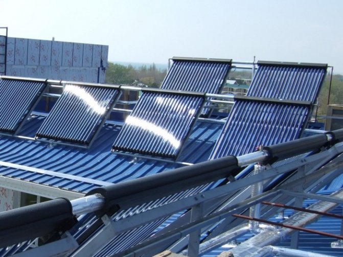
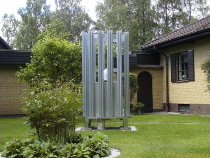
Wind energy
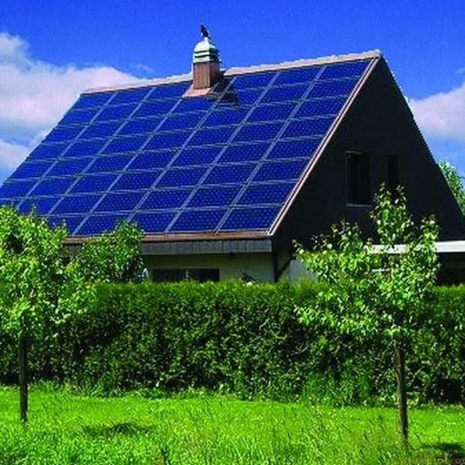
Alternative energy sources are popular all over the world
Wind energy is used by mankind for a fairly large amount of time. Windmills can generate electricity. However, the efficiency of such an alternative heating system for a private house will not exceed 59%.
The advantages and disadvantages of such heating:
- The energy received is absolutely free, if you do not take into account the costs of the equipment itself.
- For efficient work, regular winds are required, which directly depends on nature and terrain.
- Poor power quality requires additional installation of auxiliary modules.
Generator gas boiler room.
The enlarged composition of such a boiler house: a site for receiving initial fuel, mixing equipment, drying equipment, briquetters, a gas generator. The resulting generator gas is then sent either to a gas boiler (hot water or steam) with burners adapted for this gas, or to a gas compressor unit (in the case of a gas compressor unit, a generator gas purification system is required). Currently implemented in the CIS countries are projects only based on obtaining pyrolysis during the processing of wood chips.
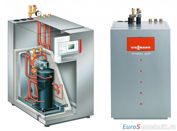
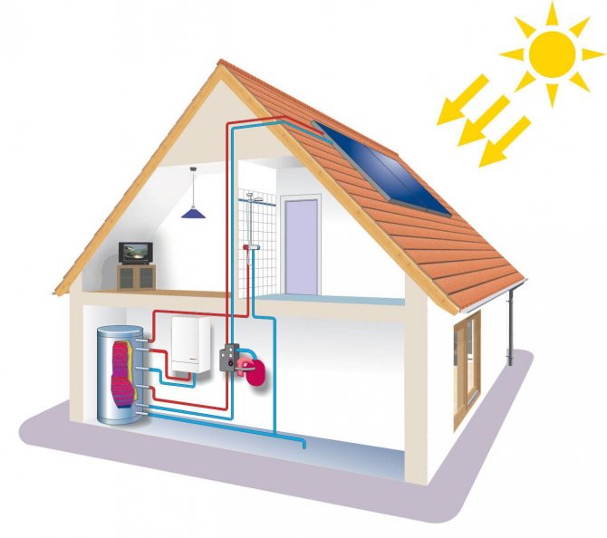
Heat pumps
Heat pump for home heating
Heat pumps are of several types. They differ in the type of coolant used.
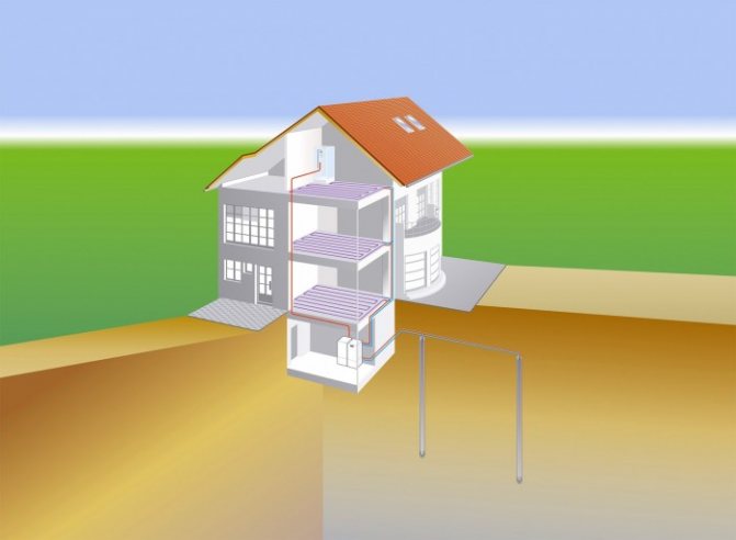
- Ground-water. A commonly used type of pump for alternative heating of a country house. The possibility of its use applies to all types of climate, since even in the coldest areas, the soil at a depth of 20-30 m has a temperature above zero. To organize such a system, wells are drilled, where heat exchangers are placed. And they, in turn, take heat from the ground to heat the house. The costs in this case include the organization of the well, the installation of a special pump and the immersion of the probes.
- Water-water. Alternative heating of a house in this way is possible in areas where groundwater flows shallowly from the surface of the earth.
- Air to water. In this case, heat is extracted from the air. Pumps for organizing the system have a relatively low cost. But it should be noted that at low temperatures, the efficiency of such a system is significantly reduced.
- Air to air. The simplest, most efficient and affordable heating method. For it you need a special compressor that will pump heat from the environment directly to the heating of the house.
At the moment, there are a fairly large number of alternative heating systems for a private house. With the right choice and organization, you can achieve effective heating of the room with minimal cost.
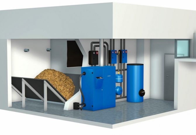
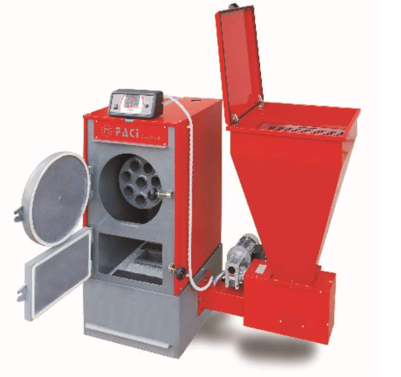
Boiler house using direct combustion.
The composition of this boiler house may vary depending on the type of biofuel to be fired.So, for example, when utilizing the husk of oilseeds, the enlarged composition of the equipment may consist of: a biofuel receiving area, fuel conveyors, fuel metering bins and the boilers themselves (hot water or steam). If it is necessary to mix several types of husk or add other types of vegetable waste to the husk, equipment for mixing, drying and briquetting is installed. The following is an example of the work of Turbopar, the development of a pre-project study for the utilization of poultry manure in Ukraine in 2010.
Ventilation
Ventilation, as an alternative heating of a private house, is hard to imagine. After all, its purpose is to remove dirty air, extraneous odors from the premises and, moreover, part of the heat leaves with the polluted air. But in order for ventilation to be used as an alternative heating of the house with your own hands, it is enough to install a heating element in its supply part. Thus, heated air will enter the room.
The maximum efficiency from such heating can be obtained with supply and exhaust ventilation, when the forced recovery of warm air and its circulation are carried out.
How the disposal of chicken manure was chosen. Brief description of the project.
The customer set the following task: a large poultry farm needed to utilize up to 200 tons of litter manure per day, with the receipt of heat and electricity. The mini-CHP works around the clock and all year round. There are no such projects on the territory of the CIS countries. The bottleneck in this project is the processing of the original biomass (litter manure), since its moisture fluctuates depending on the season. By itself, the type of fuel obtained from this biomass has an average heating value and contains many harmful substances. Various options for the preparation of fuel for subsequent supply to the boiler were considered - from direct supply to the furnace to the dust combustion method (conversion of the initial fuel into fine dust with higher combustion properties, followed by feeding this pulverized fuel into special furnaces in boilers). As a result, the following option was preliminarily adopted: - a primary fuel storage is installed with a fuel supply for 7 days of continuous operation of the CHP, - after that, equipment for mixing with other types of biofuels is installed, - drying equipment, - grinding to the required particle size - and feeding into bunkers - dispensers in front of boilers. Further, the feed from the metering hoppers is carried out directly into the steam boilers. After the boilers, one or two steam turbines of the condensing type with controlled steam flows are installed. The steam from the extraction is sent to the own needs of the boiler house (to the fuel drying section), and the poultry complex. Electric energy is used for the own needs of the poultry plant. Remains of unused electrical energy are transferred to the national power grid. Also, this mini-CHP, in addition to electrical and thermal energy, will provide a by-product of high-quality fertilizer (ash is a product of biomass combustion), which will be used either for its own needs or sold on the fertilizer market (a fertilizer packing area is provided). It deliberately does not disclose methods of utilizing flue gases of mini-CHP and a detailed description of equipment systems. Let's just say that during the implementation of the project, the enterprise will generate about 144 MW of electricity per day, the same amount of heat. The payback period for this project, taking into account all investments, will be three years. The architectural part of the project is in progress Disposal of chicken droppings.
steam boilers, hot water boilers, design of treatment facilities
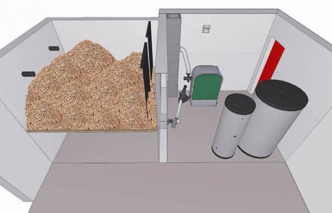
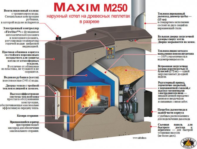
Advantages and disadvantages of biofuel heating
In modern conditions of rising prices for heating, people are looking for alternative options. And, lo and behold, there are such options. The most profitable of them is biofuel pellet heating. In Russia, biofuel is not yet as popular as in Europe, but its finest hour will soon come.
About pellets
Pellets are fuel pellets that are produced from agricultural and woodworking waste. Bark, sawdust, straw, husk, etc. are used to create biofuels. Everything that was once considered useless waste is now becoming a useful fuel.
Benefits of pellet heating
- Safety for humans and nature. Pellets are not explosive, unlike liquid fuel and gas. And the absence of foreign harmful impurities speaks of their ecological purity;
- Autonomy. You will not depend on the rise in heating prices, on interruptions at the CHP;
- Easy maintenance of pellet boilers. There are automated models that do not require regular intervention;
- Lack of unpleasant odors during the heating season;
- When pellets are burned, more heat is released than from a number of other types of fuel. When burning 1 ton of pellets, the same amount of energy is released as when burning 500 liters. diesel fuel, 1.6 tons of wood or 480 cubic meters. meters of gas.
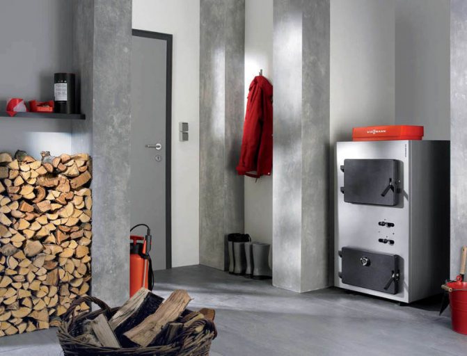
Disadvantages of pellet heating
- The cost of the boiler itself is quite high;
- It is necessary to store pellets only in a dry room;
- Purchase and delivery of pellets, boiler maintenance can be difficult if you live in a remote area;
- The cost of heating with biofuel is higher than that of mains gas.
It would seem that the disadvantages are quite significant, but the advantages are significant. How good it is to live in a warm country house, not to be afraid of a fire or gas explosion, to enjoy the smells of delicious food, not smoke.
And besides, our experience allows us to offer you the best solutions in order to minimize disadvantages.
- We, dealers of proven manufacturers, offer you to buy equipment with discounts up to 30%.
- Thanks to the experience of participating in the production of pellets, we will show you how best to equip a room for storing fuel.
- We will deliver to different areas on time.
Heating with pellets is beneficial! It is 1.5-2 times cheaper than heating on electricity, diesel fuel, gas tank (liquefied gas) and is very close to the cost of main gas, because its cost is growing every year. For convenience and autonomy, pellets are also preferable to coal and firewood.
Moreover, it is far from always possible to conduct main gas, which means that you still get the most profitable fuel in your case. In addition, we know how to make a heating system, in terms of autonomy and cost, comparable to main gas. Add fuel at the beginning of the heating season and enjoy the warmth without thinking about the problems. Our highly qualified specialists will find a way out of even the most difficult situations and help make dreams of a cozy warm home come true.
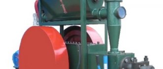
| Hot water boiler production LLC "Rimko" | Additional equipment |
| Boiler KSVm-KBasic equipment: 1.) Boiler block in casing and insulation with a combustion device 2.) Mechanized fuel supply with a fuel tank 3.) Hydroelectric power station complete with hydraulic hoses and pipes 4.) Control panel with frequency converters and electrical wires for connecting sensors and limit switches within the boiler 5 .) Instrumentation 6.) Shut-off valves 7.) Blower fan with soft insert for connection to the combustion device. Production time: 45days | Ash removal mechanism. Cyclone with ash passage, branch pipe and valve Cyclone and smoke exhauster piping flues Exhauster with reciprocating passages Fire extinguishing system Call to clarify the price |
| Boiler specifications | |||
| № | Indicator name | Value | |
| 1 | Rated heating capacity, MW (Gcal / h) | With quality fuel | |
| For fuels with high ash content | |||
| 2 | Maximum outlet water temperature, ° С | Up to ° С | |
| 3 | Excessive water pressure, no more, MPa (kgf / cm2) | 0,6(6) | |
| 4 | Boiler heating surface, m2 | Beam | |
| Convective | |||
| General | |||
| 5 | Boiler water volume, m3 | ||
| 6 | Overall dimensions (with lining), mm | Length (boiler proper) | |
| Length (with mechanical device) | |||
| Width | |||
| Height | |||
| 7 | Weight of metal parts, kg | ||
| 8 | Boiler weight with total, kg | ||
| 9 | Efficiency,% on sorted coal ("seed" or "nut") | 80-86 | |
| 10 | Efficiency,% on an ordinary coal | 70-75 | |
| 11 | Flue gas temperature ° С | 180-200 | |
| 12 | Hydraulic resistance kgf / cm2 | 0,3-0,5 | |
| 13 | Production time, days | 45 | |
The device and principle of operation of the boiler KSVm-K
Hot water steel boilers of the KSVm series are used for heating residential, industrial and other buildings with artificial water circulation, as well as for obtaining thermal energy for technological purposes.
The boiler body KSVm is a combustion chamber consisting of a gas-tight pipe system, an inclined radiation shield, suspended sections in the combustion chamber and a convective part of the boiler.
Boiler thermal insulation is lightweight on-pipe, consisting of thermal insulation and mineral wool plates. The joints of the plates and the abutments to the pipe part of the boiler are sealed with fireclay mortar.
The boiler casing is made of thin-sheet roofing with a colored polymer coating.
The ash channel is blocked by a water-cooled platform.
The drive of the knives for fuel supply and ash removal is carried out using hydraulic cylinders and an oil hydraulic station.
The knives for fuel supply and ash removal are cooled by the flow of heating water.
The boiler is equipped with a control panel, sensors and instrumentation, a set of electrical wiring within the boiler, shut-off valves and safety valves.
The mechanical fuel feed device is designed to supply coal, wood waste, milling and sod peat to the boiler furnace.
It is possible to use all types of coal with lump size up to 200 mm and ash content up to 55%, for biofuels the moisture content can exceed 55%.
The mechanical fuel feed device consists of a hopper mounted on a platform. The hopper is equipped with a door. The door faces the front plate of the boiler, which serves for manual supply of coal to the boiler furnace.
On the fuel platform there is a knife for supplying fuel and skins of burning out slags. The fuel feed knife consists of a cooled rod, on which uncooled pushers are fixed on the sides, sliding along the surface of the platform. At the end of the rod that goes into the furnace, there are one or two (depending on the power of the boiler) cooled strips.
The reciprocating movement of the fuel supply knife is carried out using a hydraulic cylinder, the body of which is fixed on the lower surface of the platform, and the rod with the rod of the fuel supply knife. The work of the hydraulic cylinder is provided by a hydraulic unit with high pressure hoses.
The mechanical fuel feed device works as follows.
The hydraulic cylinder is controlled from the control panel in manual or automatic mode.
The pusher design provides a gradual advance of fuel along the platform in the direction of the firebox. The movement of the cooled strips prevents the slag from sintering and pushes the burnt-out slag into the boiler slag hopper.
The mechanical ash removal device serves to remove ash and slag from the combustion chamber.
The mechanical ash removal device consists of a cooled ash removal knife and an upper cooled platform.
The cooled ash removal knife is located in the ash removal channel, which is covered by an upper cooled platform.
The body of the hydraulic cylinder is fixed with lugs on the outer surface of the upper platform. The hydraulic cylinder rod is connected to the lugs of the ash removal knife.
The hydraulic cylinder is driven from the hydraulic station of the mechanical fuel supply device
The hydraulic cylinder, on command from the control panel, or with the help of manual activation, sets the ash removal knife in motion. The design of the pushers and the reciprocating movement of the ash removal knife ensure the movement of ash along the ash channel and its removal outside the boiler room.
Ash and slags come out with a fraction of no more than 20 ... 25 mm and a temperature of no more than 100оС.
The boiler control panel is used to control the electric motors of the draft devices of boilers, a hydroelectric station, regulate the power of boiler units, and monitor the operating and emergency parameters of boilers.
The boiler control panel performs the following functions:
Turning on and off the fan and indication and blocking (inability to turn on when the smoke exhauster is off), smooth speed control.
Switching on and off the smoke exhauster with indication, smooth speed control and operation depending on the vacuum (automatic mode).
Switching the hydraulic station on and off with indication, working in automatic mode (switching on and off during the operation of the hydraulic cylinders at long intervals of time).
Control of hydraulic drives for fuel supply and ash removal with the ability to perform the following functions:
- in automatic mode with adjustment of the time interval between fuel feeds (ash removal) from 0 minutes and 6 seconds to 9 minutes and 54 seconds, which is set by the corresponding switches
- fuel supply (ash removal) in manual mode.
The end positions of the pushers are monitored by limit switches that turn off the electro valves of the hydraulic cylinders when the extreme points are reached.
If there is a delay in the movement of mechanisms (jamming, shutdown of the hydraulic station, other disturbances in the movement of mechanisms), the hydraulic station is turned off and the alarm is turned on.
Turning on the boiler in the "Automatic" mode (in direct water).
Automatic maintenance of vacuum (by changing the speed of the smoke exhausters).
Alarms for the following parameters:
- overheating of the boiler.
- high water pressure in the boiler.
- low water pressure in the boiler.
- lack of vacuum in the boiler furnace.
- disturbances in the operation of the hydraulic system.
Disabling the alarm when firing up or stopping the boiler.
The hydroelectric station is designed to ensure the operation of mechanical fuel supply and mechanical ash removal from boilers.
The hydraulic pump in the oil tank generates an oil pressure of about 13 MPa.
Biofuel power plants and thermal power plants
Power plant based on a steam turbine generator
A traditional steam power plant consists of two main sections: - A section for the preparation of a heat carrier (steam) - a turbogenerator as well as a number of auxiliary elements that ensure stable and safe operation of the entire installation, both in stand-alone mode and when connected to a common network.
Generation of electricity using a steam turbine generator is by far the most widespread in the world power engineering. All the bottlenecks of this technology have long been known and worked out, both in Russian and foreign engineers and equipment suppliers. For the correct operation of the turbine generator, a certain amount of steam with certain characteristics is required. It does not matter how the steam is obtained. Technologies for generating steam using solid biofuels have been known for a long time and well. A number of Russian and foreign manufacturers of boiler and furnace equipment offer customers steam boilers of various capacities with different steam parameters for solid biofuel.
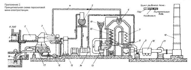
Schematic diagram of a steam power plant based on a steam boiler and a steam turbine. Specification:
| 1. Transformer 2. Electric generator 3. Steam turbine 4. Steam line 5. Deaerator 6. Superheater 7. Economizer 8. Air heater 9. Blower 10. Electrostatic precipitators | 11. Exhaust fan 12. Chimney 13. Mill 14. Feed pump 15. Regenerative heater 16. Condensate pump 17. Steam condenser 18. Circulation pump 19. Fuel hopper 20. Firebox screen pipes |
Based on materials: book. "Stationary steam turbines", A.D. Trukhny, S.M. Losev, M. 1981
DESCRIPTION OF TECHNOLOGY:
Fuel from the fuel storage is supplied by a conveyor to the bunker 19. From the bunker, the fuel enters the mill 13, in which it is ground to a pulverized state. Hot air, heated in the air heater 8. The hot air is mixed with fuel dust and through the burners of the boiler is supplied to its furnace - the chamber in which the fuel is burned.
The walls of the furnace are lined with 20 screens - pipes to which feed water is supplied from the economizer 7. In the screens, the water is heated and evaporated, turning into dry saturated steam. The diagram shows a direct-flow boiler. Drum boilers (E-4-1.4-250ОИ - double-drum boiler) have become widespread in the screens of which the water is heated, and the separation of steam from the boiler water takes place in the drum.
Further, dry saturated steam enters the superheater 6, in which its temperature and, consequently, potential energy increases.
The gaseous products of fuel combustion, having given up their main heat to the feed water, enter the pipes of the economizer 7 and the air heater 8, in which they are cooled to a temperature of 140-1600 C and are directed through the smoke exhauster 11 to the chimney 12. In the electrostatic precipitators 10 dry fly ash is collected ...
The steam obtained at the outlet of the installation is fed through the steam line 4 to the steam turbine 3. Expanding in it, the steam rotates its rotor connected to the rotor of the electric generator 2, in the windings of which an electric current is generated. The current flows to the windings of the transformer 1.
The steam leaving the turbine 3 enters the condenser 17 - a heat exchanger, through the tubes of which cold water continuously flows, supplied by the circulation pump 18 from the river, reservoir or special cooling device (cooling tower). The steam coming from the turbine into the annular space of the condenser condenses and flows down; The resulting condensate is fed by the condensate pump 16 through the regenerative heater 15 to the deaerator 5. In the heater 15, the condensate temperature rises due to the heat of the steam taken from the turbine. This makes it possible to reduce the fuel consumption in the boiler and increase the efficiency of the power plant. Deaeration takes place in the deaerator - the gases dissolved in it are removed from the condensate. At the same time, the deaerator tank is a container for boiler feed water.
From the deaerator feed water is supplied to the boiler by the feed pump 14. Thus, the technological steam-water cycle of converting the chemical energy of the fuel into the mechanical energy of rotation of the rotor of the turbine unit is closed.
| Benefits | disadvantages |
| - Old, proven, reliable technology - High power quality, stable current parameters - Moderate capital investment per unit of power (starting from 1-2 MW) | - High cost of installation at low installed power (up to 1 MW) - Limited ability to regulate the generated power - High explosion hazard class (steam boiler requires additional approvals) |
Steam boilers
Generating equipment
Biomass CHP plant