Ultrasonic flow meter working principle
The measurements are carried out by measuring the difference in the transit time of ultrasound signals from sensors (emitters / receivers). The time difference resulting from the passage of the signal through the measuring channel is directly proportional to the average flow rate of the liquid / gas. Based on this time difference, the volumetric flow rate of the measured liquid or gas is calculated based on acoustic laws. In the diagram below.
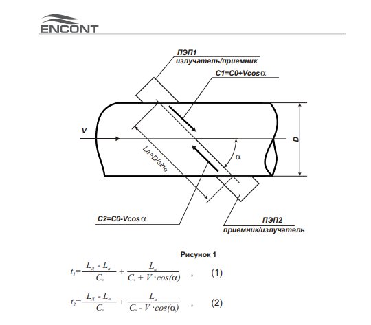
- t1, t 2 - the propagation time of the ultrasonic pulse along the flow and against the flow
- Lа is the length of the active part of the acoustic channel
- Ld is the distance between the PEP membranes
- C is the speed of ultrasound in still water
- V is the speed of movement of water in the pipeline
- a - angle in accordance with Figure 1.
- PEP1, PEP2 - piezoelectric sensor
Probe sensors manufactured by AC Electronics have various modifications, with an enhanced output signal, sensors with dust and moisture protection IP68, for high temperatures of +200 degrees, for corrosive liquids, etc. There is a huge selection of flow meter manufacturers, but we would like to highlight AC Electronics, which has been producing US 800 flow meters for more than 20 years, has established itself as a reliable, high-quality manufacturer of devices.
Ultrasonic flow meters: modern models
US-800; ECHO-R-02 (free-flow); GEOSTREAM 71 (Doppler); VIRS-U; AKRON-01 (01C, 01P); AKRON-02; DNEPR-7; ULTRAFLOW 54; MULTICAL 62; ULTRAHEAT T150 / 2WR7; KARAT-RS; KARAT-520; IRVIKON SV-200; RUS-1, -1A, -1M, -Exi; PRAMER-510; UFM 001; UFM 005; UFM 3030; GOOY-5; RISE URSV-5XX C; RISE URSV-510V C; RISE URSV-322-XXX; RISE URSV-311; RISE URSV-PPD-Ex-2XX; RISE URSV-1XX C; RISE RSL-212, -222; RISE OF RBP; RISE OF PRC; SONO 1500 CT; StreamLux SLS-700P (portable handheld); StreamLux SLS-700F (consignment note); SOFREL LT-US; ETALON-RM; UVR-011-Du25 ... 7000 (Ex, HART); PRAMER-517; StreamLux SLD-800F / 800P; Streamlux SLD-850F, -850P; StreamLux SLO-500F.
Portable flow meters include such flow meters as some models: Akron, Dnepr, StreamLux, etc.
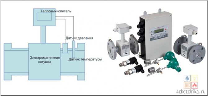
Electromagnetic flowmeters
The device of electromagnetic flowmeters is based on the law of electromagnetic induction, known as Faraday's law. When a conductive liquid, such as water, passes through the lines of force of a magnetic field, an electromotive force is induced. It is proportional to the speed of movement of the conductor, and the direction of current is perpendicular to the direction of movement of the conductor.
In electromagnetic flowmeters, fluid flows between the poles of a magnet, creating an electromotive force. The device measures the voltage between two electrodes, thereby calculating the volume of liquid passing through the pipeline. This is a reliable and accurate method, because the device itself does not affect the flow rate of the liquid, and due to the absence of moving parts, the equipment is durable.
Advantages of electromagnetic flowmeters:
- Moderate cost.
- There are no moving or stationary parts in the cross section.
- Large dynamic range of measurements.
Disadvantages:
- The performance of the device is affected by magnetic and conductive precipitation.
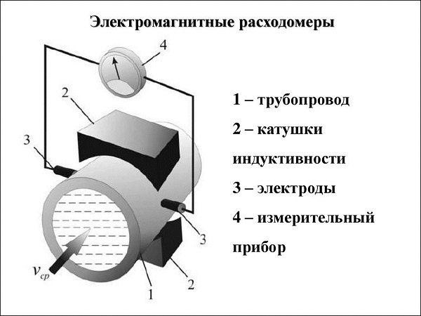
The principle of operation of an electromagnetic flowmeter
Types of flow meters
Mechanical flow meters: high-speed meters, volumetric meters, roller-blade flow meters, gear flow meters, tank and stopwatch.
Lever-pendulum flowmeters.
Variable differential pressure flowmeters: flowmeters with restriction devices, Pitot tube, flowmeters with hydraulic resistance, with a pressure head, with a pressure amplifier, shock-jet, centrifugal flowmeters.
Constant differential pressure flowmeters: rotameters.
Optical flow meters: laser flow meters.
Ultrasonic flow meters: ultrasonic time-pulse, ultrasonic phase shift, ultrasonic Doppler, ultrasonic correlation.
Electromagnetic flowmeters.
Coriolis flow meters.
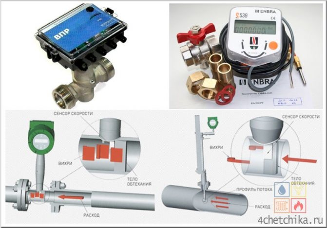
Vortex flowmeters.
Thermal flowmeters: thermal boundary layer flowmeters, calorimetric.
Precision flow meters.

Thermal flow meters are those based on measuring the flow-dependent effect of thermal action on a stream or a body in contact with the stream. Most often they are used to measure gas flow and less often to measure liquid flow.
Thermal flow meters are distinguished by:
· Heating method;
· Location of the heater (outside or inside the pipeline);
· The nature of the functional relationship between the flow rate and the measured signal.
The electric ohmic heating method is the main one; inductive heating is almost never used in practice. Also, in some cases, heating using an electromagnetic field and using a liquid heat carrier is used.
By the nature of the thermal interaction with the flow, thermal flow meters are subdivided into:
· calorimetric
(with electric ohmic heating, the heater is located inside the pipe);
· thermoconvective
(the heater is located outside the pipe);
· thermo-anemometric
.
Have calorimetric
and
thermoconvective
flowmeters measure the temperature difference AT of gas or liquid (at constant heating power W) or power W (at ΔТ == const). Hot-wire anemometers measure the resistance R of the heated body (at constant current i) or current i (at R = const).
Hot-wire anemometric
instruments for measuring local flow rates appeared earlier than others. The internally heated calorimetric flowmeters, which appeared later, did not find noticeable use. Later, thermoconvective flow meters began to be developed, which, due to the external arrangement of the heater, are increasingly used in industry.
Thermoconvective
flowmeters are divided into quasi-calorimetric (the difference in flow temperatures or heating power is measured) and thermal boundary layer (the difference in temperature of the boundary layer or the corresponding heating power is measured). They are used to measure flow mainly in pipes of small diameter from 0.5-2.0 to 100 mm. To measure the flow rate in pipes of large diameter, special types of thermoconvective flow meters are used:
· Partial with a heater on the bypass pipe;
· With a heat probe;
· With external heating of a limited section of the pipe.
The advantage of calorimetric and thermoconvective flow meters is the invariability of the heat capacity of the substance being measured when measuring the mass flow rate. In addition, there is no contact with the measured substance in thermoconvective flow meters, which is also their significant advantage. The disadvantage of both flow meters is their high inertia. To improve performance, corrective circuits are used, as well as pulse heating. Hot-wire anemometers, unlike other thermal flow meters, are very low-response, but they serve primarily to measure local velocities. The reduced error of thermoconvective flow meters usually lies within ± (l, 5-3)%, for calorimetric flow meters ± (0.3-1)%.
Thermal flowmeters heated by an electromagnetic field or a liquid heat carrier are used much less frequently. The electromagnetic field is created using high frequency, ultra high frequency or infrared energy emitters. The advantage of the first thermal flow meters with heating by an electromagnetic field is their relatively low inertia. They are intended mainly for electrolytes and dielectrics, as well as selectively gray aggressive liquids.Flowmeters with a liquid heat carrier are used in industry to measure the flow rate of slurries, as well as to measure the flow rate of gas-liquid flows.
The temperature limit for the use of thermoconvective flow meters is 150-200 ° C, but in rare cases it can reach 250 ° C. When heated by an electromagnetic field or a liquid heat carrier, this limit can be increased to 450 ° C.
Calorimetric flow meters
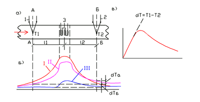
Figure 1 - Calorimetric flow meter
(a - schematic diagram; b - temperature distribution; c - dependence of ΔT on the flow rate QM at W = const)
Calorimetric flow meters are based on the dependence on the heating power of the mass-average flow temperature difference. The calorimetric flow meter consists of a heater 3, which is located inside the pipeline, and two thermal converters 1 and 2 for measuring temperatures before T1 and after T2 of the heater. Thermal converters are usually located at equal distances (l1 = 1g) from the heater. The distribution of heating temperatures depends on the consumption of the substance. In the absence of flow, the temperature field is symmetric (curve I), and when it appears, this symmetry is violated. At low flow rates, the temperature T1 drops more (due to the influx of cold matter) than the temperature T2, which can even increase at low flow rates (curve II). As a result, at first, as the flow rate increases, the temperature difference ΔT = Т2 - Т1 increases. But with a sufficient increase in the flow rate QM, the temperature T1 will become constant, equal to the temperature of the inflowing substance, while T2 will fall (curve III). In this case, the temperature difference ΔT will decrease with increasing flow rate QM. The growth of ΔT at small values of Qm is almost proportional to the flow rate. Then this growth slows down, and after reaching the maximum of the curve, ΔТ begins to drop according to the hyperbolic law. In this case, the sensitivity of the device decreases with increasing flow rate. If, however, ΔT = const is automatically maintained by changing the heating power, then there will be a direct proportionality between the flow rate and the power, with the exception of the region of low speeds. This proportionality is an advantage of this method, but the device of the flow meter turns out to be more complex.
The calorimetric flowmeter can be calibrated by measuring the heating power ΔT. This requires, first of all, good insulation of the pipe section where the heater is located, as well as a low heater temperature. Further, both the heater and the thermistors for measuring T1 and T2 are made in such a way that they evenly overlap the cross-section of the pipeline. This is done to ensure that the mass-average temperature difference ΔТ is measured correctly. But at the same time, the velocities at different points of the section are different, therefore the average temperature over the section will not be equal to the average temperature of the flow. A swirler consisting of a number of inclined blades is placed between the heater and the thermal converter for measuring T2, which provides a uniform temperature field at the outlet. The same swirler located before the heater will eliminate its heat exchange with the thermal converter.
If the device is designed to measure high flow rates, then the temperature difference ΔТ at Qmax is limited to 1-3 ° in order to avoid high power consumption. Calorimetric flow meters are used only for measuring very low flow rates of liquids, since the heat capacity of liquids is much higher than that of gases. Basically, these devices are used to measure gas flow.
Calorimetric flow meters with internal heating are not widely used in industry due to the low reliability of operation under operating conditions of heaters and thermal converters located inside the pipeline. They are used for various research and experimental work, as well as exemplary instruments for checking and calibrating other flow meters.When measuring mass flow, these devices can be calibrated by measuring the power W and the temperature difference ΔT. Using calorimetric flowmeters with internal heating, it is possible to provide flow measurement with a relative reduced error of ± (0.3-0.5)%.
Thermal convection meters
Thermal convective flow meters are those in which the heater and thermocouple are located outside the pipeline, and not inserted inside, which significantly increases the operational reliability of flow meters and makes them convenient for use. Heat transfer from the heater to the measured substance is carried out by convection through the pipe wall.
Varieties of thermoconvective flow meters can be grouped into the following groups:
1.quasi-calorimetric flowmeters:
o with symmetrical arrangement of thermal converters;
o with a heater combined with a thermal converter;
o with heating directly to the pipe wall;
o with asymmetric arrangement of thermal converters.
2. flowmeters measuring the difference in temperature of the boundary layer;
3. special types of flowmeters for large diameter pipes.
For devices of the 1st group, the calibration characteristics, as well as for calorimetric flow meters (see Fig. 1), have two branches: ascending and descending, and for devices of the 2nd group - only one, since their initial temperature T transducer is insulated from the heating section of the pipe. Quasi-calorimetric flowmeters are mainly used for pipes of small diameter (from 0.5-1.0 mm and above).
The larger the pipe diameter, the less the central part of the flow heats up, and the device increasingly measures only the temperature difference of the boundary layer, which depends on its heat transfer coefficient, and hence on the flow rate [1]. At small diameters, the entire flow is heated and the temperature difference of the flow is measured on both sides of the heater, as in calorimetric flow meters.
Thermoanemometers
Hot-wire anemometers are based on the relationship between the loss of heat from a continuously heated body and the speed of the gas or liquid in which this body is located. The main purpose of hot-wire anemometers is to measure local velocity and its vector. They are also used for flow measurement when the relationship between local and average flow rates is known. But there are designs of hot-wire anemometers specifically designed to measure flow.
Most hot-wire anemometers are of the thermoconductive type with a stable heating current (the electrical resistance of the body is measured, which is a function of velocity) or with a constant resistance of the heated body (the heating current is measured, which should increase with increasing flow velocity). In the first group of thermoconductive converters, the heating current is simultaneously used for measurement, and in the second, the heating and measuring currents are separated: a heating current flows through one resistor, and the current required for measurement flows through the other.
The advantages of hot-wire anemometers include:
· Large range of measured speeds;
· High-speed response, allowing to measure speeds varying with a frequency of several thousand hertz.
The disadvantage of hot-wire anemometers with wire sensitive elements is fragility and a change in calibration due to aging and recrystallization of the wire material.
Thermal flow meters with radiators
Due to the high inertness of the considered calorimetric and thermoconvective ones, thermal flow meters were proposed and developed in which the flow is heated using the energy of an electromagnetic field of a high frequency HF (about 100 MHz), an ultrahigh frequency of a microwave (about 10 kHz) and infrared range of the IR.
In the case of heating the flow using the energy of a high-frequency electromagnetic field, two electrodes are installed outside the pipeline to heat the flowing liquid, to which high-frequency voltage is supplied from a source (for example, a powerful lamp generator). The electrodes together with the liquid between them form a capacitor. The power released in the form of heat in the volume of a liquid in an electric field is proportional to its frequency and depends on the dielectric properties of the liquid.
The final temperature depends on the speed of movement of the liquid and decreases with an increase in the latter, which makes it possible to judge the flow rate by measuring the degree of heating of the liquid. At a very high speed, the liquid no longer has time to warm up in a condenser of limited size. In the case of measuring the flow rate of electrolyte solutions, it is advisable to measure the degree of heating by measuring the electrical conductivity of the liquid, since it strongly depends on the temperature. This achieves the highest speed of the flow meter. The devices use the method of comparing the electrical conductivity in a tube where a liquid flows, and in a similar closed container with electrodes, where the same liquid is at a constant temperature [1]. The measuring circuit consists of a high-frequency generator, which supplies voltage through isolation capacitors to two oscillatory circuits. A condenser with a flowing liquid is connected in parallel to one of them, and a condenser with a stationary liquid is connected to the other. A change in the flow rate of a stationary liquid will lead to a change in the voltage drop on one of the circuits, and, consequently, in the voltage difference between both circuits, which is measured. This scheme can be applied to electrolytes.
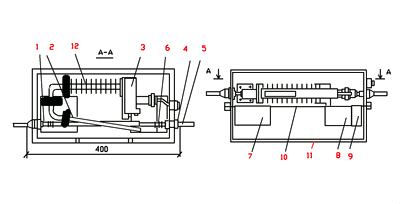
Figure 2 - Converter of a thermal flow meter with a microwave emitter.
High-frequency heating is also used for dielectric fluids, based on the dependence of the dielectric constant of the fluid on temperature. When used to heat the flow of an ultra-high frequency field, it is supplied with the help of a tubular waveguide to a tube through which the measured substance moves.
Figure 2 shows a transducer for such a flow meter. The field generated by a continuous magnetron 3 of the M-857 type with a power of 15 W is fed through a waveguide 2. The initial part of the waveguide for cooling is equipped with fins 12. The measured liquid moves through a fluoroplastic tube 1 (inner diameter 6 mm, wall thickness 1 mm). Tube 1 is connected to inlet nozzles 5 by means of nipples 4. Part of tube 1 passes inside waveguide 2. In the case of polar liquids, tube 1 crosses waveguide 2 at an angle of 10-15 °. In this case, the reflection of the field energy by the tube wall and by the fluid flow will be minimal. In the case of a weakly polar liquid, to increase its amount in the electromagnetic field, the tube 1 is placed in the waveguide parallel to its axis. To control the degree of heating of the liquid outside the tube, capacitive converters 6 are placed, which are included in the oscillatory circuits of two high-frequency generators 7 and 8. The signals of these generators are fed to the mixing unit 9, from which the difference frequency of the beats of the input signals is taken. The frequency of these signals depends on the flow rate. The flow transducer is mounted on the board 10 and placed in a shielding protective casing 11. The frequency of the microwave field generator is selected at the maximum value, and the frequency of the measuring generators 7 and 8 at the minimum value of the dielectric loss tangent tgδ.
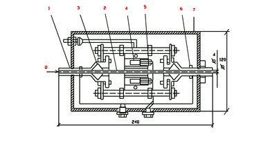
Figure 3 - Thermal flow meter converter with IR emitter
Figure 3 shows a transducer for a thermal flow meter with an infrared light source. As a source of IR radiation, small-sized quartz-iodine lamps of the KGM type were used, which can create large specific radiation fluxes (up to 40 W / cm2).A tube 2 made of quartz glass (transparent to infrared radiation) is connected to two nozzles 1 by means of seals 3, around which heating lamps 4 with screens 5 covered with a layer of silver and cooled with water are tightly located. Thanks to the silver layer, the screens reflect the rays well, which concentrates the radiation energy and reduces its loss to the environment. The temperature difference is measured by a differential thermopile 6, the joints of which are located on the outer surface of the nozzles 1. The entire structure is placed in a heat-insulating casing 7. The inertia of quartz-iodine emitters is no more than 0.6 s.
The measurement error of these flow meters does not exceed ± 2.5%, the time constant is within 10–20 s. Microwave and IR emitters are suitable only for small pipe diameters (no more than 10 mm) and mainly for liquids. They are not suitable for monatomic gases.
Ultrasonic Liquid Flow Meter US-800
Advantages: little or no hydraulic resistance, reliability, speed, high accuracy, noise immunity. The device also works with high-temperature liquids. The AC Electronics company produces high-temperature probes PEP at +200 degrees.
Developed taking into account the peculiarities of operation in the Russian Federation. Has built-in protection against overvoltage and network noise. The primary converter is made of stainless steel!
It is produced with ready-made ultrasonic transducers for diameters: from 15 to 2000 mm! All flange connections are in accordance with GOST 12820-80.
Specially created and ideally suited for use in water utilities, heating systems, housing and communal services, energy (CHP), industry!
Please note that it is necessary to operate the flow meters and carry out maintenance in accordance with the operation manual.
The flowmeter-counter US800 has a certificate RU.C.29.006.A No. 43735 and is registered in the State Register of Measuring Instruments of the Russian Federation under No. 21142-11
If used in areas subject to state supervision and control in the Russian Federation, the measuring device is subject to inspection by the bodies of the State Metrological Service.
Characteristics of the error of ultrasonic flow meters US800
| UPR diameter, mm | Flow range ** | Relative error,% | ||
| flow rate by indicator and frequency output | flow rate on analog output | volume by indicator | ||
| 15-2000 single-beam | Qmin - QP | ± 2,0 | ± 2,5 | ± 2,0 |
| 15-2000 single-beam | QP - Qmax | ± 1,5 | ± 2,0 | ± 1,5 |
| 100 - 2000 dual-beam | Qmin - QP | ± 1,5 | ± 2,0 | ± 1,5 |
| 100 - 2000 dual-beam | QP - Qmax | ± 0,75 | ± 1,5 | ± 0,75 |
** Qmin is the minimum flow rate; QP — transient flow rate; Qmax - maximum flow rate
Table of characteristics of the volumetric flow rate of liquid of ultrasonic flowmeters US-800
| DN, mm | Volumetric flow rate of liquid, m3 / hour | ||||
| Q max maximum | Q р1 transitional Т ‹60 ° С | Q р2 transitional Т ›60 ° С | Q min1 minimum Т ‹60 ° С | Q min2 minimum Т ›60 ° С | |
| 15 | 3,5 | 0,3 | 0,2 | 0,15 | 0,1 |
| 25 | 8 | 0,7 | 0,5 | 0,3 | 0,25 |
| 32 | 30 | 2,2 | 1,1 | 0,7 | 0,3 |
| 40 | 45 | 2,7 | 1,3 | 0,8 | 0,4 |
| 50 | 70 | 3,4 | 1,7 | 1,0 | 0,5 |
| 65 | 120 | 4,4 | 2,2 | 1,3 | 0,65 |
| 80 | 180 | 5,4 | 2,7 | 1,6 | 0,8 |
| 100 | 280 | 6,8 | 3,4 | 2 | 1 |
| 150 | 640 | 10,2 | 5,1 | 3 | 1,5 |
| 200 | 1100 | 13,6 | 6,8 | 4 | 2 |
| 250 | 2000 | 17 | 8,5 | 10 | 5 |
| 300 | 2500 | 20,4 | 10,2 | 12 | 6 |
| 350 | 3500 | 23,8 | 11,9 | 14 | 7 |
| 400 | 4500 | 27,2 | 13,6 | 16 | 8 |
| 500 | 7000 | 34 | 17 | 20 | 10 |
| 600 | 10000 | 40,8 | 20,4 | 24 | 12 |
| 700 | 14000 | 47,6 | 23,8 | 28 | 14 |
| 800 | 18000 | 54,5 | 27,2 | 32 | 16 |
| 900 | 23000 | 61,2 | 30,6 | 36 | 18 |
| 1000 | 28000 | 68 | 34 | 40 | 20 |
| 1200 | 0.034xDUhDU | 0.068xDU | 0.034xDU | 0.04xDU | 0.02xDU |
| 1400 | 0.034xDUhDU | 0.068xDU | 0.034xDU | 0.04xDU | 0.02xDU |
| 1400-2000 | 0.034xDUhDU | 0.068xDU | 0.034xDU | 0.04xDU | 0.02xDU |
Preparing the device for operation and taking measurements
1.
Remove the device from the packaging. If the device is brought into a warm room from a cold one, it is necessary to allow the device to warm up to room temperature for at least 2 hours.
2.
Charge the batteries by connecting the mains adapter to the device. Charging time for a fully discharged battery is at least 4 hours. In order to extend the service life of the battery, it is recommended to carry out a full discharge once a month until the device is automatically turned off, followed by a full charge.
3.
Connect the measuring unit and measuring probe with a connecting cable.
4.
If the device is equipped with a software disk, install it on the computer. Connect the device to a free COM-port of the computer with appropriate connecting cables.
5.
Switch on the device by short pressing the "Select" button.
6.
When the device is turned on, a self-test of the device is carried out for 5 seconds. In the presence of internal faults, the device on the indicator signals the number of the fault, accompanied by a sound signal. After successful testing and completion of loading, the indicator displays the current value of the heat flux density. An explanation of testing faults and other errors in the operation of the device is given in the section
6
of this operating manual.
7.
After use, turn off the device by briefly pressing the "Select" button.
8.
If you intend to store the device for a long time (more than 3 months), remove the batteries from the battery compartment.
Below is a diagram of switching in the "Run" mode.
Preparation and carrying out of measurements during heat engineering tests of enclosing structures.
1. Measurement of the density of heat fluxes is carried out, as a rule, from the inside of the enclosing structures of buildings and structures.
It is allowed to measure the density of heat fluxes from the outside of the enclosing structures if it is impossible to measure them from the inside (aggressive environment, fluctuations of air parameters), provided that a stable temperature on the surface is maintained. The control of the heat exchange conditions is carried out using a temperature probe and means for measuring the heat flux density: when measured for 10 minutes. their readings must be within the measurement error of the instruments.
2. Areas of the surface are selected specific or characteristic of the entire tested enclosing structure, depending on the need to measure the local or average heat flux density.
Selected areas for measurements on the enclosing structure must have a surface layer of the same material, the same surface treatment and state, have the same conditions for radiant heat transfer and must not be in the immediate vicinity of elements that can change the direction and value of heat fluxes.
3. Areas of the surface of the enclosing structures, on which the heat flux converter is installed, are cleaned until visible and tactile roughness is eliminated.
4. The transducer is tightly pressed over its entire surface to the enclosing structure and fixed in this position, ensuring constant contact of the heat flux transducer with the surface of the investigated areas during all subsequent measurements.
When fixing the transducer between it and the enclosing structure, no air gaps are allowed. To exclude them, a thin layer of technical petroleum jelly is applied on the surface at the measurement points, overlapping the surface irregularities.
The transducer can be fixed along its lateral surface using a solution of stucco, technical petroleum jelly, plasticine, a rod with a spring and other means that exclude distortion of the heat flow in the measurement zone.
5. In on-line measurements of the heat flux density, the unsecured surface of the transducer is glued with a layer of material or painted over with paint with the same or close degree of emissivity with a difference Δε ≤ 0.1 as that of the material of the surface layer of the enclosing structure.
6. The reading device is located at a distance of 5-8 m from the measurement site or in an adjacent room to exclude the influence of the observer on the value of the heat flux.
7. When using devices for measuring emf, which have restrictions on the ambient temperature, they are located in a room with an air temperature permissible for the operation of these devices, and the heat flux transducer is connected to them using extension wires.
8. The equipment according to claim 7 is prepared for operation in accordance with the operating instructions for the corresponding device, including taking into account the required holding time of the device to establish a new temperature regime in it.
Preparation and measurement
(when carrying out laboratory work on the example of the laboratory work "Investigation of means of protection against infrared radiation")
Connect the IR source to a power outlet. Switch on the IR radiation source (upper part) and the IPP-2 heat flux density meter.
Install the head of the heat flux density meter at a distance of 100 mm from the IR radiation source and determine the heat flux density (average value of three to four measurements).
Manually move the tripod along the ruler, setting the measuring head at the distances from the radiation source indicated in the form of Table 1, and repeat the measurements. Enter the measurement data in the form in table 1.
Construct a graph of the dependence of the flux density of IR radiation from the distance.
Repeat measurements according to PP. 1 - 3 with different protective screens (heat-reflecting aluminum, heat-absorbing fabric, metal with a blackened surface, mixed - chain mail). Enter the measurement data in the form of Table 1. Build graphs of the dependence of the flux density of IR radiation from the distance for each screen.
Table form 1
| Thermal protection type | Distance from the source r, cm | IR radiation flux density q, W / m2 | ||||
| q1 | q2 | q3 | q4 | q5 | ||
| 100 | ||||||
| 200 | ||||||
| 300 | ||||||
| 400 | ||||||
| 500 | ||||||
Estimate the effectiveness of the protective action of the screens according to the formula (3)
Install a protective screen (as instructed by the teacher), place a wide vacuum cleaner brush on it. Switch on the vacuum cleaner in the air sampling mode, simulating the exhaust ventilation device, and after 2-3 minutes (after establishing the thermal mode of the screen) determine the intensity of thermal radiation at the same distances as in paragraph 3. Evaluate the effectiveness of the combined thermal protection using the formula (3 ).
The dependence of the intensity of thermal radiation on the distance for a given screen in the exhaust ventilation mode is plotted on the general graph (see item 5).
Determine the effectiveness of protection by measuring the temperature for a given screen with and without exhaust ventilation according to formula (4).
Construct graphs of the efficiency of protection of exhaust ventilation and without it.
Put the vacuum cleaner in “blower” mode and turn it on. Directing the air flow to the surface of the specified protective screen (spray mode), repeat the measurements in accordance with paragraphs. 7 - 10. Compare the results of measurements pp. 7-10.
Fix the vacuum cleaner hose on one of the racks and turn on the vacuum cleaner in the “blower” mode, directing the air flow almost perpendicular to the heat flow (slightly opposite) - imitation of an air curtain. Using the IPP-2 meter, measure the temperature of the IR radiation without and with the "blower".
Build the graphs of the "blower" protection efficiency according to the formula (4).
Application areas of flow meters
- Any industrial enterprise.
- Enterprises of the chemical, petrochemical, metallurgical industries.
- Measurement of fluid flows in main pipelines.
- Heat supply (heating points, central heating stations) and cold supply (ventilation and air conditioning)
- Water treatment (boiler houses, CHP)
- Water supply, sewerage and sewerage (sewage pumping station, treatment facilities)
- Food industry.
- Extraction and processing of minerals.
- Pulp and paper industry.
- Mechanical engineering and metallurgy.
- Agriculture.
- Apartment heat, water and gas meters.
- Household water and heat meters
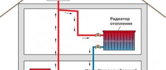
Methods for calculating the amount of heat
The formula for calculating gigacalories by the area of \ u200b \ u200bthe room
It is possible to determine the cost of a gigacalorie of heat depending on the availability of an accounting device. Several schemes are used on the territory of the Russian Federation.
Payment without meters during the heating season
The calculation is based on the area of the apartment (living rooms + utility rooms) and is made according to the formula:
P = SхNхT, where:
- P is the amount to be paid;
- S - the size of the area of an apartment or house in m²;
- N - heat spent for heating 1 square in 1 month in Gcal / m²;
- T is the tariff cost of 1 Gcal.
Example. The energy provider for a one-room apartment of 36 squares supplies heat at 1.7 thousand rubles / Gcal.The consumer rate is 0.025 Gcal / m². For 1 month, heating services will be: 36x0.025x1700 = 1530 rubles.
Payment without meter for the whole year
Without an accounting device, the formula for calculating P = Sx (NxK) xT also changes, where:
- N is the rate of heat energy consumption per 1 m2;
- T is the cost of 1 Gcal;
- K is the coefficient of the frequency of payment (the number of heating months is divided by the number of calendar months). If the reason for the absence of an accounting device is not documented, K increases by 1.5 times.
Example. One-room apartment has an area of 36 m2, the tariff is 1,700 rubles per Gcal and the consumer rate is 0.025 Gcal / m2. Initially, it is required to calculate the frequency factor for 7 months of heat supply. K = 7: 12 = 0.583. Further, the numbers are substituted into the formula 36x (0.025x0.583) x1700 = 892 rubles.
The cost in the presence of a general house meter in the winter
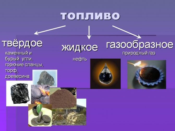
The cost of a gigacalorie depends on the type of fuel used for a high-rise building.
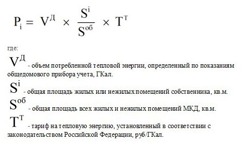
This method allows you to calculate the price for central heating with a common meter. Since heat energy is supplied to the entire building, the calculation is based on the area. The formula P = VxS / StotalxT is applied, where:
- P is the monthly cost of services;
- S is the area of a separate living space;
- Stot - the size of the area of all heated apartments;
- V - general readings of the collective metering device for the month;
- T is the tariff cost of 1 Gcal.
Example. The area of the owner's dwelling is 36 m2, of the entire high-rise building - 5000 m2. Monthly heat consumption is 130 Gcal, the cost of 1 Gcal in the region is 1700 rubles. Payment for one month is 130 x 36/5000 x 1700 = 1591 rubles.
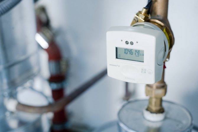
Metering devices are available in all apartments
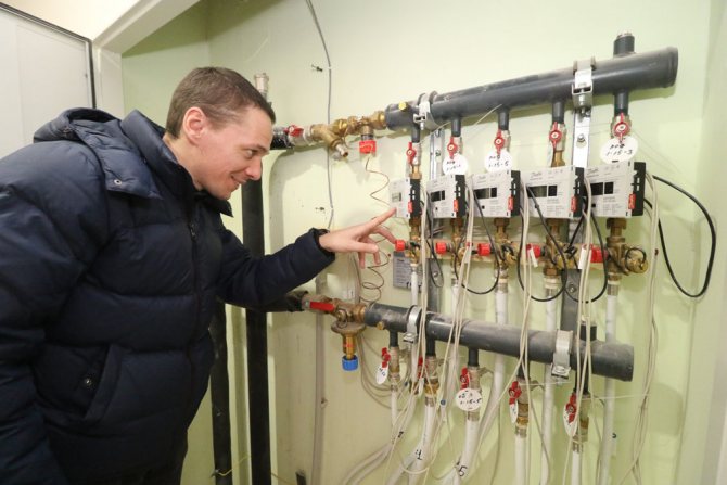
The cost of heating services for an individual meter is 30% lower
Depending on the presence of a collective meter at the entrance and a personal device in each of the apartments, there is a change in readings, but this does not apply to tariffs for heating services. The payment is divided between all owners according to the parameters of the area as follows:
- The difference in heat consumption on the general house and personal meters is considered according to the formula Vdiff. = V- Vпом.
- The resulting figure is substituted into the formula P = (Vpom. + VpxS / Stot.) XT.
The meanings of the letters are deciphered as follows:
- P is the amount to be paid;
- S - indicator of the area of a separate apartment;
- Stot. - the total area of all apartments;
- V - collective heat input;
- Vpom - individual heat consumption;
- Vр - the difference between the readings of individual and household appliances;
- T is the tariff cost of 1 Gcal.
Example. In a one-room apartment of 36 m2, an individual counter is installed, showing 0.6. 130 is knocked out on the brownie, a separate group of devices gave 118. The area of the high-rise building is 5000 m2. Monthly heat consumption - 130 Gcal, payment for 1 Gcal in the region - 1700 rubles. First, the difference in readings Vр = 130 - 118 = 12 Gcal is calculated, and then - a separate payment P = (0.6 + 12 x 36/5000) x 1700 = 1166.88 rubles.
Application of a multiplying factor
On the basis of PP No. 603, the heating fee is charged 1.5 times more if the meter has not been repaired within 2 months, if it is stolen or damaged. A multiplying factor is also set if homeowners do not transmit the readings of the device or twice did not allow specialists to check the technical condition to it. You can independently calculate the multiplying coefficient using the formula P = Sx1.5 NxT.
The formula for calculating heat energy (per 1 square meter)
The exact formula for calculating heat energy for heating is taken in the ratio of 100 W per 1 square. In the course of calculations, it takes the form:
Q = (S × 100) × a × b × c × d × e × f × g × h × i × j × k × l × m.
Correction factors are denoted by Latin letters:
- a - the number of walls in the room. For the inner room, it is 0.8, for one external structure - 1, for two - 1.2, for three - 1.4.
- b - the location of the outer walls to the cardinal points. If the room faces north or east - 1.1, south or west - 1.
- c - the ratio of the room to the wind rose. The house on the upwind side is 1.2, on the leeward side - 1, parallel to the wind - 1.1.
- d - climatic conditions of the region. Indicated in the table.
| Temperature, degrees | Coefficient |
| From -35 | 1,5 |
| -30 to -34 | 1,3 |
| -25 to -29 | 1,2 |
| -20 to -24 | 1,1 |
| -15 to -19 | 1 |
| -10 to -14 | 0,9 |
| To 10 | 0,7 |
- e - insulation of the wall surface. For structures without insulation - 1.27, with two bricks and minimal insulation - 1, good insulation - 0.85.
- f is the height of the ceilings.Indicated in the table.
| Height, m | Coefficient |
| Up to 2.7 | 1 |
| 2,8-3 | 1,05 |
| 3,1-3,5 | 1,1 |
| 3,6-4 | 1,15 |
- g - features of floor insulation. For basements and plinths - 1.4, with insulation on the ground - 1.2, in the presence of a heated room below - 1.
- h - features of the upper room. If at the top there is a cold mountain - 1, an attic with insulation - 0.9, a heated room - 0.8.
- i - design features of window openings. In the presence of double glazing - 1.27, single-chamber double-glazed windows - 1, two-chamber or three-chamber glass with argon gas - 0.85.
- j - general parameters of the glazing area. It is calculated by the formula x = ∑Sok / Sп, where ∑Sok is a common indicator for all windows, Sп is the square of the room.
- k - presence and type of entrance opening. A room without a door -1, with one door to the street or loggia - 1.3, with two doors to the street or loggia - 1.7.
- l - battery connection diagram. Specified in the table
| Inset | Features of the | Coefficient |
| Diagonal | Feed at the top, return at the bottom | 1 |
| Unilateral | Feed at the top, return at the bottom | 1,03 |
| Double-sided | Return and feed at the bottom | 1,13 |
| Diagonal | Feed at the bottom, return at the top | 1,25 |
| Unilateral | Feed at the bottom, return at the top | 1,28 |
| Unilateral | Feed and return at the bottom | 1,28 |
- m - the specifics of the installation of radiators. Indicated in the table.
| Connection type | Coefficient |
| On the wall is open | 0,9 |
| Top, hidden by a shelf or window sill | 1 |
| Closed on top by a niche | 1,07 |
| Covered by a niche / window sill on top and overlay from the end | 1,12 |
| With decorative body | 1,2 |
Before using the formula, create a diagram with data for all coefficients.
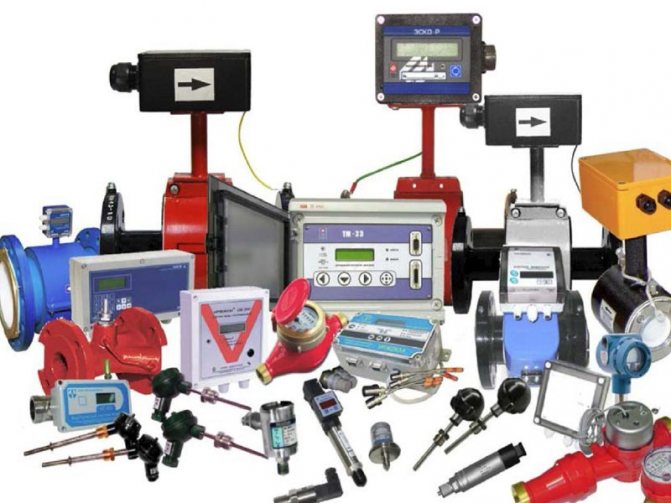
Frequently asked questions
What kind of flow meters are on sale?
The following products are constantly on sale: Industrial ultrasonic flow meters and heat meters, heat meters, apartment heat meters, ultrasonic stationary in-line flow meters for liquids, ultrasonic stationary overhead and portable overhead flow meters.
Where can I see the characteristics of flow meters?
The main and most complete technical characteristics are indicated in the instruction manual. See pages 24-27 for the installation conditions and requirements, in particular the lengths of the straight runs. The wiring diagram can be found on page 56.
What liquid does the US 800 ultrasonic flow meter measure?
Ultrasonic flowmeters US 800 can measure the following liquids:
- cold and hot water, network water, hard water, drinking water, service water,
- sea, salt, river water, silted water
- clarified, demineralized, distilled, condensate
- waste water, polluted water
- stratal, artesian and Cenomanian waters
- water pressure for high pressure, 60 atm (6 MPa), 100 atm (10 MPa), 160 atm (16 MPa), 250 atm (25 MPa)
- pulp, suspensions and emulsions,
- fuel oil, heating oil, diesel fuel, diesel fuel,
- alcohol, acetic acid, electrolytes, solvent
- acids, sulfuric and hydrochloric acid, nitric acid, alkali
- ethylene glycols, propylene glycols and polypropylene glycols
- surfactants surfactants
- oil, industrial oil, transformer oil, hydraulic oil
- motor, synthetic, semi-synthetic and mineral oils
- vegetable, rapeseed and palm oil
- oil
- liquid fertilizers UAN
How many pipelines can be connected to the US 800 ultrasonic flowmeter?
The ultrasonic flowmeter US-800 can serve, depending on the version: Execution 1X, 3X - 1 pipeline; Execution 2X - up to 2 pipelines at the same time; Execution 4X - up to 4 pipelines simultaneously.
Multiple beams are made to order. US 800 flowmeters have two versions of ultrasonic flow transducers: single-beam, double-beam, and multi-beam. Multi-beam designs require fewer straight sections during installation.
Multichannel systems are convenient in metering systems where several pipelines are located in one place and it would be more convenient to collect information from them into one device.
The single-channel version is cheaper and serves one pipeline. The two-channel version is suitable for two pipelines. Two-channel has two channels for flow measurement in one electronic unit.
What is the content of gaseous and solid substances in% by volume?
A prerequisite for the content of gas inclusions in the measured liquid is up to 1%. If this condition is not observed, stable operation of the device is not guaranteed.
The ultrasonic signal is blocked by air and does not pass through it; the device is in a "failure", inoperative state.
The solids content in the standard version is not desirable more than 1-3%, some disturbance in the stable operation of the device is possible.
There are special versions of the US 800 flow meter that can measure even heavily contaminated liquids: river water, silted water, waste water, sewage, slurry, sludge water, water containing sand, mud, solid particles, etc.
The possibility of using the flow meter for measuring non-standard liquids requires mandatory approval.
What is the production time of devices? Whether there are available?
Depending on the type of products required, the season, the average shipment time is from 2 to 15 working days. The production of flow meters goes on without interruption. The production of flow meters is located in Cheboksary at its own production base. Components are usually in stock. Each device comes with an instruction manual and a passport for the device. The manufacturer cares about his customers, and therefore all the detailed necessary information on the installation and installation of the flow meter can be found in the instructions (operation manual) on our website. The flow meter must be connected by a qualified technician or other certified organization.
What types of ultrasonic flow meters is the US 800?
There are several types of ultrasonic flow meters according to the principle of operation: time-pulse, Doppler, correlation, etc.
US 800 relates to time-pulsed ultrasonic flow meters, and measures flow based on the measurement of pulses of ultrasonic vibration through a moving fluid.
The difference between the propagation times of ultrasonic pulses in the forward and reverse directions relative to the movement of the liquid is proportional to the speed of its flow.
What are the differences between ultrasonic and electromagnetic devices?
The difference is in the principle of work and some functionality.
Electromagnetic is measured based on the electromagnetic induction that occurs when a fluid moves. Of the main disadvantages - not all liquids are measured, exactingness to the quality of the liquid, high cost for large diameters, inconvenience of repair and verification. The disadvantages of electromagnetic and cheaper (tachometric, vortex, etc.) flow meters are very noticeable. The ultrasonic flowmeter has more advantages than disadvantages.
Ultrasonic is measured by measuring the propagation time of ultrasound in a stream.
Undemanding to liquid quality, measurement of non-standard liquids, oil products, etc., fast response time.
Wide range of applications, any diameters, maintainability, any pipes.
Installation of such flow meters will not be difficult.
Look for ultrasonic flowmeters in the range we offer.
You can see the photos of the devices on our website. Look for detailed and complete photos of flow meters on the corresponding pages of our website.
What is the depth of the archive in US 800?
The US800 ultrasonic flowmeter has a built-in archive. The depth of the archive is 2880 hourly / 120 daily / 190 monthly records. It should be noted that not in all versions the archive is displayed on the indicator: if EB US800-1X, 2X, 3X - the archive is formed in the nonvolatile memory of the device and is displayed via communication lines, it is not displayed on the indicator. if EB US800-4X - the archive can be displayed on the indicator.
The archive is displayed via communication lines via the digital RS485 interface to external devices, for example, a PC, laptop, via a GSM modem to the dispatcher's computer, etc.
What is ModBus?
ModBus is an open communication industrial protocol for data transmission via the digital RS485 interface. The description of the variables can be found under the heading documentation.
What do the letters and numbers mean in the flow meter configuration record: 1. "A" 2. "F" 3. "BF" 4. "42" 5. "without COF" 6. "IP65" 7. "IP68" 8. "P" "- verification
A - archive, not present in all executions and not in all executions is displayed on the indicator. Ф - flanged version of the flow transducer. BF is a wafer-type flow transducer. 42 - in some versions, designation of the presence of a 4-20 mA current output. KOF - a set of counter flanges, fasteners, gaskets (for flange versions) Without KOF - accordingly, the set does not include counter flanges, fasteners, gaskets. IP65 - dust and moisture protection IP65 (protection against dust and splashes) IP68 - dust and moisture protection IP68 (protection against dust and water, sealed) P - method of verification by imitation method
Calibration of flow meters is organized on the basis of appropriately accredited enterprises. In addition to the imitation method of verification, some diameters of flow meters, on request, are verified by the pouring method on a pouring installation.
All offered products comply with GOST, TU, OST and other regulatory documents.
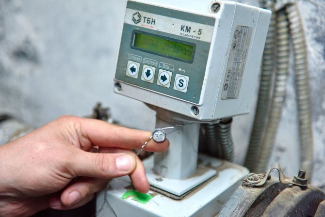
Thermal energy measurement systems
The practice of periodic verification of flow meters has shown that up to half of the array of monitored instruments must be recalibrated.
In general, the practice of periodic verification of flow meters (diameters up to 150 mm) on flow-measuring calibration facilities has shown that up to half of the array of monitored instruments does not fit into the established accuracy standards and must be recalibrated. It is worth discussing the issue of admission during periodic control: in the West, the tolerance is doubled compared to the tolerance at release from production. The calibration interval is established by no more than tradition; tests for long-term exposure to operational factors - hot water - are not carried out. As far as I know, there is not a single setup for such tests.
There are also two approaches to the structure of measuring systems and methods for performing measurements of the amount of heat. Or build a methodology on the basis of measuring systems, the channels of which are channels of flow, temperature, pressure, and all calculations are performed by the computational (or measuring and computational) component of the system (Fig. 1); or when creating measuring systems based in channels on the use of heat meters according to EN 1434 (Fig. 2).
The difference is fundamental: a simple channel with a heat meter according to EN 1434 (with a standardized error and the established procedure for its control) or simple channels "out of sync". In this latter case, it is necessary to validate the system software operating with the measurement results of simple channels.
More than two dozen thermal energy measuring systems are included in the Russian register. The measuring components of the channels of these systems are multichannel heat meters in accordance with GOST R 51649-2000, mounted in house heat and water metering units (Fig. 3).
An additional requirement for such heat meters is the availability of a special software product for servicing the system interface and the availability for periodic adjustment of the internal clock of the heat meter, so that a single accurate time is provided in the IC.
What should be included in the procedure for verifying such a measuring system for the amount of heat? In addition to checking the availability of certificates of verification of the measuring components of the channels - checking the functioning of the connecting components, no more.
In conclusion, it should be noted that the issues discussed in this review are reflected in the reports and discussions of the annual Russian conferences "Commercial metering of energy resources" in the city of St. Petersburg, "Metrological support for metering energy resources" in the southern city of Adler, etc.