What the system consists of and how does it work
In order for heat to flow from the boiler room to the heating devices, an intermediary is used in the water system - a liquid. A heat carrier of this type moves through the pipeline and heats the rooms in the house, and all of them can have a different area. This factor makes such a heating system popular.
The movement of the coolant can be carried out in a natural way, the circulation is based on the principles of thermodynamics. Due to the different density of cold and heated water and the slope of the pipeline, water moves through the system.
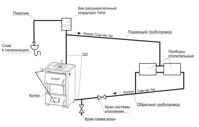
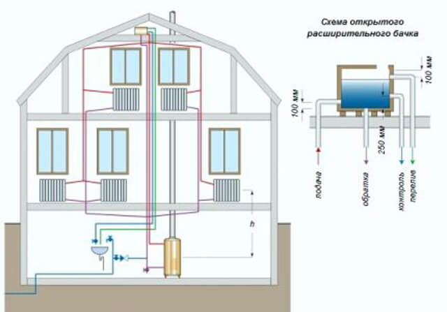
One of the important elements of the heating system is an open expansion tank, which receives excess heated liquid. It is this element that stabilizes the coolant pressure. The main condition is that the tank should be located at the highest point of the heating system.
Open heat supply operates according to the following scheme:
- The boiler heats up water and supplies it to heating devices in every room of the house.
- On the way back, excess liquid goes into the open-type expansion tank, its temperature drops, and the water returns back to the boiler.
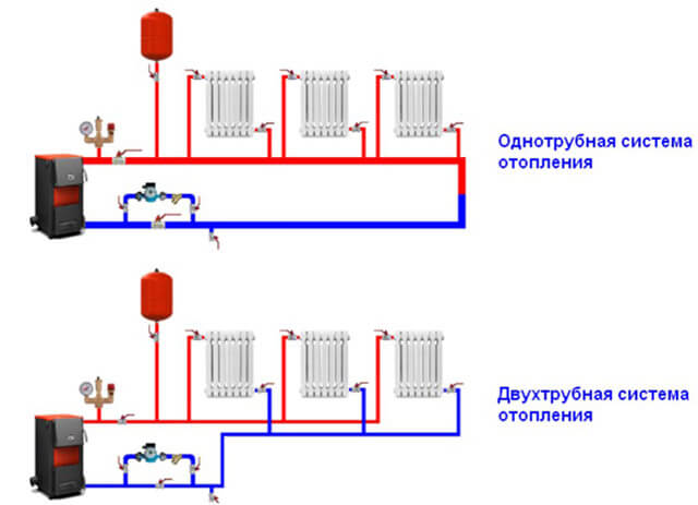
One-pipe heating systems involve the use of one main line for supply and return. Two-pipe systems have independent flow and return pipes. When deciding to independently mount a dependent heating system, it is better to choose a one-pipe scheme, it is simpler, more accessible and has an elementary design.
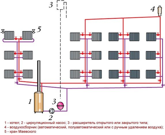
One-pipe heat supply consists of the following elements:
- Heating boiler.
- Batteries or radiators.
- Expansion tank.
- Pipes.
A simplified scheme implies the use of pipes with a cross section of 80-100 mm instead of radiators, but it should be borne in mind that such a system is less efficient in operation.
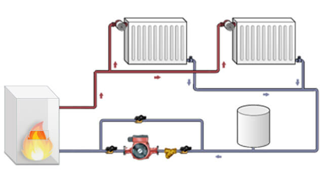
A two-pipe open heating system with a pump is more costly in material terms and is characterized by complex installation. However, in this case, all the disadvantages of a one-pipe system are practically eliminated, which makes it possible to compensate for the costs and complexity of the device. All heating devices receive a coolant with the same temperature, while the cooled liquid is sent to the return line.
Types of two-pipe system
Depending on the type of circuit, the direction of the flow of water and the methods of its movement, the type of wiring and the installation scheme, two-circuit systems can be diverse. Let's understand this in more detail.
Open and closed heating wiring
Closed wiring assumes the presence of a membrane-type expansion tank, this allows:
- operate the system at elevated pressure;
- use not only water as a heat carrier, but also a special antifreeze, characterized by a low freezing point (usually down to -40⁰C), as well as specialized additives and additives.
In addition, the membrane tank can be installed at any point in the pipeline. Usually it is mounted in the return line, if there is a pump - immediately after it.
In open wiring, an open-type expansion tank is used, which is installed at the top of the system. This concept implies the arrangement of additional air and drainage complexes. The openness of the circuit provokes:
- corrosive processes due to the high presence of oxygen;
- gradual evaporation of the liquid, which increases its consumption;
- the latter limits the possibilities of using antifreeze, the vapors of which are unsafe.
Closed wiring is considered safer.
Coolant movement: dead-end and associated
Two-pipe complexes use one of two schemes for the movement of the coolant:
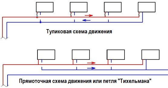
- dead-end (oncoming);
- passing, called "Tichelman's loop".
In a dead-end system, the supply of coolant and return flows in different directions. To facilitate balancing, a needle valve or thermostatic valve will be required on each battery.
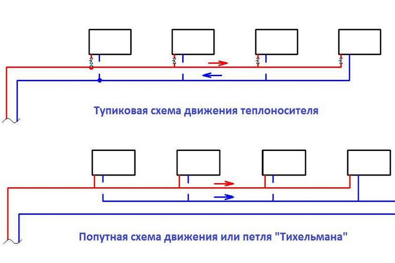
The scheme of the passing movement of the coolant is recommended for particularly extended heating systems. It is easier to balance and adjust, and the installation of radiators with the same number of sections automatically balances the heating circuit.
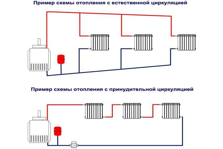
Forced and natural circulation
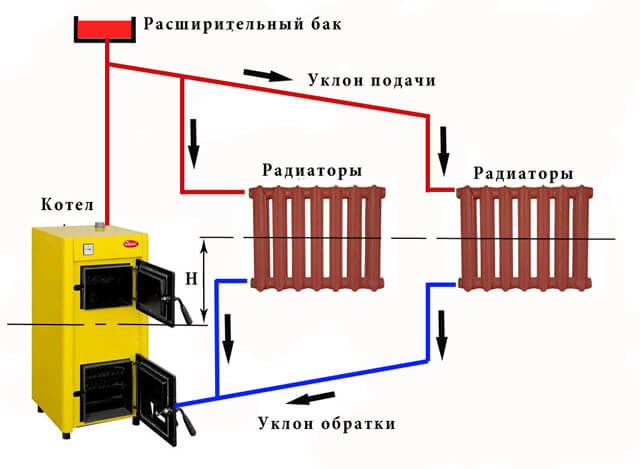
For natural circulation of the coolant, the pipeline is laid with a slope, and an expansion tank is installed at the top point. This concept is most often used for one-story houses. In addition, the autonomy of the system from electricity allows you not to worry about turning it off.
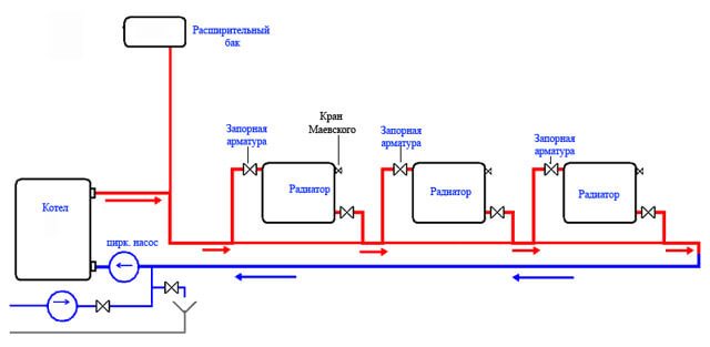
To organize a heating system with forced circulation, a pump is additionally installed in the return line, which provides more active fluid movement.
In this case, it is necessary to install air vent valves or Mayevsky taps on the radiators.
- Allows the use of pipes with a smaller cross-section. Under the action of the pressure created by the pump, the coolant is "pressed through" without difficulty.
- Provides more accurate maintenance of the set temperatures.
- In parallel, you can equip a water "warm floor".
- The expansion tank can be installed anywhere.
However, the concept of forced circulation is electricity dependent. To minimize this dependence, you will have to install an additional uninterruptible power supply.
Two-storey buildings with two-pipe heating must be equipped with a pump.
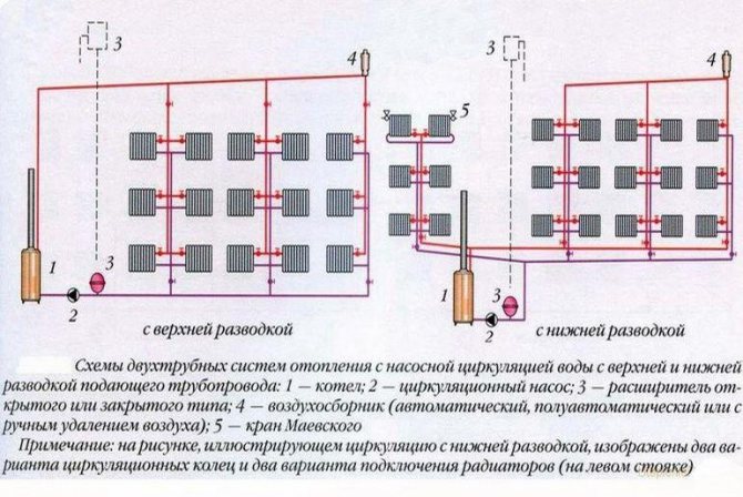
Wiring type: top and bottom
According to the method of water supply, the upper and lower wiring methods are distinguished.
With the top feed, the main pipe is placed under the ceiling, from where the supply pipes go down to the radiators. The return line runs down the floor. Due to the height difference, the pressure of the optimum force is created so as not to resort to an additional installation of the pump.
Disadvantages of top routing:
- This installation scheme is not recommended for small rooms.
- Low aesthetic appeal.
- Requires more pipes.
With a bottom supply, both lines are located at the bottom (on the floor, in a subfield, in a semi-basement or basement room), while the supply pipe is located higher than the return.
This concept requires a responsible approach to the location of the boiler and expansion tank:
- natural circulation obliges to place the boiler below the level of the radiators;
- with forced circulation, the location of the boiler does not matter;
- the expansion vessel is mounted at the highest point of the system.
In addition, the installation diagram with lower wiring:
- minimizes pipe consumption;
- requires the connection of an additional air line, which will allow air to be removed from the circuit;
- available for do-it-yourself implementation without the involvement of professionals;
- looks more aesthetically pleasing.
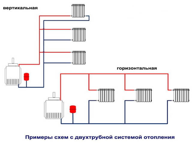
Mounting scheme: horizontal and vertical type of layout
According to the installation scheme, two-pipe systems are divided into vertical and horizontal.
The vertical layout is designed to work in multi-storey buildings (two or more).
- To connect heating radiators on each floor, more pipes are required.
- The air rushing upwards automatically leaves the circuit by means of an expansion tank or a drain valve.
The horizontal wiring diagram is intended for operation in one-story, maximum two-story buildings.Bleeding air from the circuit occurs through the "Mayevsky" valve.
A horizontal heating system with a bottom wiring is the most popular solution among the owners of small-storey private houses.
Features of arrangement and operation
If the choice is made in favor of heating with a pump and an expansion tank, then when arranging heat supply in a house, some of its features should be taken into account:
- In order for the coolant to circulate normally, the boiler should be located at the lowest point of the system, and the expansion tank at the highest point.
- It is best to place the expansion tank in the attic of your home. If this room is not heated, then the tank and the riser require good thermal insulation during the cold season.
- The system should have a minimum number of turns, connections and fittings.
- Due to the slow circulation of the coolant in the system, strong heating must not be allowed. Boiling water significantly reduces the service life of heating devices and pipes.
- If in winter time the operation of the heating system is not planned, then the liquid must be drained without fail. This will help to avoid the destruction of pipes, batteries and boiler.
- It is very important to constantly monitor the water level in the expansion tank and add liquid if necessary. Failure to comply with this rule will lead to the formation of air jams, therefore, heating devices will work less efficiently.
- The best option for the coolant is water, since antifreeze is highly toxic, which makes it impossible to use it in open heating systems. This option can be used if it is not possible to drain the coolant in winter.
When assembling a heating system, including a heating scheme for a garage with a circulation pump, it is important to correctly calculate the cross-section of the pipes and the degree of their slope. These values are regulated by SNiP 2.04.01-85. In systems where the coolant circulates naturally, the pipes have a larger cross section than in forced circulation heating. Moreover, in the first case, the length of the pipes is much shorter. As for the slope, it is recommended to do it in systems with natural circulation of liquid, while the regulatory documents establish a slope of 2-3 mm per one meter of the contour.
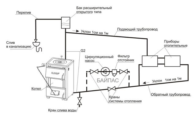
Open heating systems diagrams
In open-type heating systems, the coolant can circulate in two ways. In the first case, the movement is carried out in a natural way, its second name is gravitational circulation. In open-type heating with a pump, additional equipment forces the liquid to move, this option is called forced or artificial movement. You need to choose one or another method depending on the area of the room, the number of floors and the thermal regime used.
Gravitational circulation
In systems where the coolant circulates in a natural way, there are no mechanisms to facilitate the movement of fluid. The process is carried out due to the expansion of the heated heat carrier. In order for a scheme of this type to work effectively, a booster riser with a height of 3.5 meters or more is installed.
The pipeline in a heating system with natural circulation of liquid has some length restrictions, in particular, it should not exceed 30 meters. Consequently, such heat supply can be used in small buildings; in this case, houses with an area not exceeding 60 m2 are considered the best option. The height of the house and the number of floors are also of great importance when installing the booster riser. One more factor should be taken into account, in a heating system of a natural circulation type, the coolant must be heated to a certain temperature; in a low-temperature mode, the required pressure is not created.
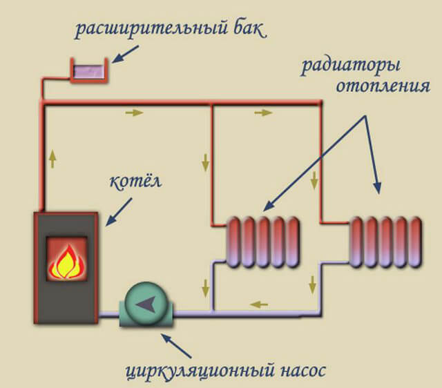
A scheme with gravitational fluid motion has certain capabilities:
- Combination with underfloor heating systems. In this case, a circulation pump is installed on the water circuit leading to the heating elements. Otherwise, the operation is carried out as usual, without interruption even in the absence of power supply.
- Working with a boiler. The device is installed in the upper part of the system, but at a lower level than the expansion tank is located. In some cases, a pump is installed on the boiler so that it runs smoothly. However, it should be understood that in such a situation the system becomes forced, which makes it necessary to install a check valve to prevent liquid recirculation.
Systems with artificial induction of the movement of the coolant
Diagrams of an open heating system with a pump in any case imply the use of an appropriate device. This allows you to increase the speed of movement of the liquid and reduce the time for heating the house. The coolant flow in this case moves at a speed of about 0.7 m / s, so heat transfer becomes more efficient and all sections of the heat supply system are heated equally.
In the process of installing an open-type heating system with a pump, several features should be taken into account:
- The presence of a built-in circulation pump requires connection to the power supply system. For uninterrupted operation in the event of an emergency power outage, the pump is recommended to be installed on the bypass.
- The pumping equipment must stand on the return pipe in front of the boiler inlet, at a distance of up to 1.5 meters from it.
- The pump cuts into the pipeline, taking into account the direction of movement of the coolant.
The installation of the pump also has its own characteristics, it is located on the bypass pipe between two shut-off valves. If there is electricity in the network, which is necessary for the operation of the pumping equipment, then the taps are shut off. In this case, the coolant passes through a bypass elbow with a circulation pump. In the absence of voltage, the valves are opened, allowing the system to operate in gravity mode.
The direction of movement of the coolant
Along with the above classification, all two-line forced circulation heating systems are divided into the following types:
- Direct-flow;
- Dead end.
Direct-flow ones are characterized by the fact that both in the direct line and in the reverse, the liquid moves in the same direction.
Coolant flow patterns
Dead ends have different directions of movement of the coolant in different lines.
I must say that all such schemes, as noted earlier, in the vast majority of cases today are equipped with a circulation pump. But the fundamental existence of circuits with a lower wiring with natural movement of the coolant is possible. When installing such structures, it is important to remember that the minimum slope of the pipeline should be 1 percent of the total length.
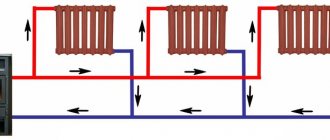
One-pipe and two-pipe heating systems
In any heat supply system, water is heated in the boiler, then enters the heating devices, after which it returns to the boiler through the return pipe. However, such a movement of the coolant can be carried out in different ways.
A single-pipe system assumes the movement of liquid through one large-diameter pipe, and all heating devices are located on the same line.
A single-pipe heating system with natural movement of the coolant has several advantages:
- Use of a minimum amount of consumables.
- Simple assembly of all elements and their connection.
- The minimum number of pipes in the room.
Of the disadvantages of such a pipe layout, attention should be paid to the uneven heating of the batteries. With a distance from the gas boiler for an open heating system, the batteries heat up less, respectively, their heat transfer decreases.
The two-pipe system is gaining in popularity. Due to the fact that the heating devices are connected to both the supply and return pipes, the system forms a kind of closed ring.
Among the advantages of this scheme are the following:
- Uniform heating of all heating devices.
- An individual temperature can be set for each radiator.
- High reliability of the heating system.
Of the minuses of a two-pipe heating system, a more complex installation of communication branches inside the room and significant investments and labor costs stand out.
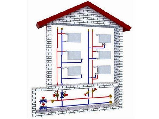
Two-pipe horizontal heating system
| Author | Share | Rate |
| Victor Samolin |
Interesting on the topic:
The use of cross-linked polyethylene for heating systems
How to pressurize the heating system
Warm water floor - the best solution for heating your home
Comments on this article
bigcitiesHop Thank you for the detailed diagram of the top-wired two-pipe heating system. Perfect for my two-story house. The air collector was set to be automatic.
02/17/2016 at 13:14
Coolant supply methods
The hot fluid line can be positioned in several ways. Depending on this, the eyeliner is divided into upper and lower.
The upper distribution implies the supply of hot coolant through the main riser and distribution to the radiators through the distribution pipes. This system is best used in private residential buildings and cottages one or two stories high.
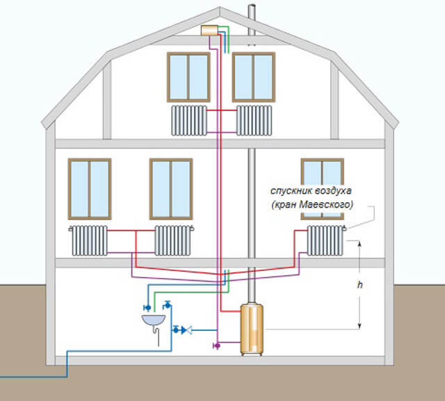
A heating system with a lower wiring is considered more efficient and practical. In this case, the supply and return pipes are located side by side, and the coolant moves from bottom to top. Hot water flows through the heaters and returns to the boiler for the open heating system through a return pipe. To prevent air accumulation in the heating system, a Mayevsky crane is installed on each radiator.
Bottom and top wiring
Among other things, the division is carried out by the method of laying the pipeline, that is, by the method of installing the wiring. Distinguish schemes:
- With bottom wiring;
- With top wiring.
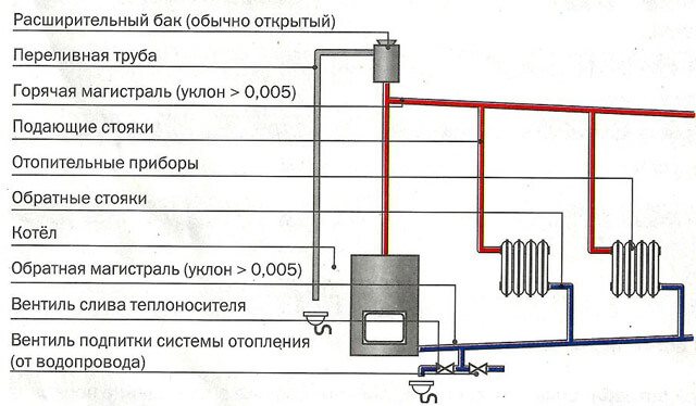
Top routing
The most important difference from the rest is that this type has an expansion tank, which is installed at the highest point. In addition, this expansion tank must be located above all other elements.
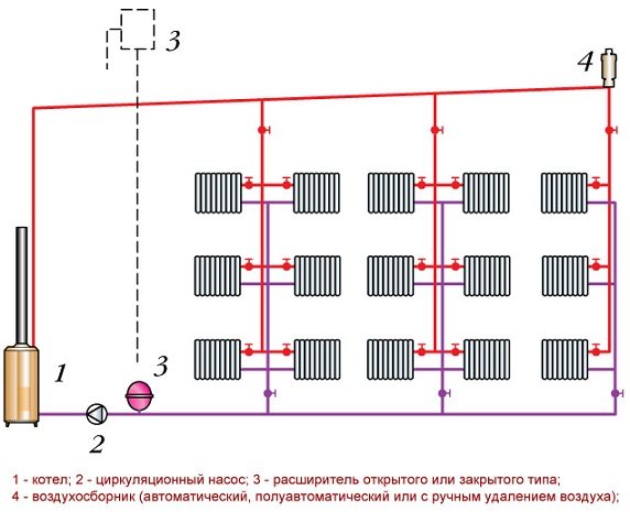
Top routing of the two-pipe system
Structurally, such a system should contain the following elements:
- Heating boiler;
- Circulation pump;
- Expansion tank;
- Air collector, which can be manual, automatic or semi-automatic.
Advice! Such structures should be assembled with your own hands only in a pre-insulated attic, or the expansion tank itself should be additionally insulated.
It should be noted that such a scheme will not work for a one-story building with a sloping roof.
Bottom wiring
All systems with bottom wiring have a peculiarity in that the supply line is usually located in the basement. Often the supply and return lines are located on the floor.
Bottom routing of the two-pipe system
Structurally, this scheme will include the following elements:
- Heating boiler;
- Circulation pump;
- Expansion tank;
- Air collector;
- Mayevsky crane.
I must say that regardless of where the supply pipes are located, the boiler must be located below the level of the return line.
The disadvantage is that additional installation of the air bleed line is required.
Main risers
Depending on the location of the main risers, the wiring can be vertical or horizontal.
In the first case, radiators on each floor are connected to a vertical riser. Such a system has its own characteristics:
- No air pockets are formed.
- Effective heating of buildings several storeys high.
- The ability to connect heating radiators on each floor.
- more complex installation of heat meters in apartments of multi-storey buildings.
With horizontal wiring, all floor radiators are connected to a single riser. The main advantage of such a scheme is the use of fewer materials for installation and, accordingly, a lower cost of the system.
Necessary calculations
It is very important to correctly perform hydraulic calculations; on their basis, the pipe diameter is selected for an open-type heating circuit with a pump.
To calculate the circulating pressure, the following parameters should be considered:
- Distance from the central axis of the boiler to the center of the heater. The larger this value, the more stable the coolant circulates.
- Water pressure at the outlet of the boiler and at the inlet to it. The circulating head is determined by the difference in fluid temperature.
The diameter of the pipeline largely depends on the material from which they are made. Steel pipes for the heating system must have a cross section of at least 5 cm. After wiring, pipes of a smaller diameter can be used, but the wiring, on the contrary, should expand.
The parameters of the expansion tank are also of great importance. For efficient operation of the system, a reservoir should be used that has a volume of about 5% of the volume of all fluid in the system. Failure to do so may result in pipes bursting or excess water splashing out.
Principle of operation
A dead-end heating scheme is the most common scheme. Its fundamental difference from the passing system is that the movement of the coolant along the supply and return lines is carried out in different directions.
The hot coolant flow moves along the supply line from the boiler towards the radiator system. The coolant enters the radiator, gives off its heat and is discharged into the return line, along which it moves immediately in the opposite direction - to the boiler.
Most often, a two-pipe dead-end heating system works when heating a private house using forced circulation of a coolant with a lower wiring. This scheme makes it possible to use pipes with a smaller diameter, significantly reduces the inertness of the system. In addition, it is applicable even with long pipelines.
At the same time, the dead-end scheme also allows the implementation of a gravity system with top wiring. Such systems are chosen mainly for their non-volatility. There is no need to connect to the mains as the circulation pump is not used.
System complete set
Open-type heating in a private house requires the installation of a boiler that runs on solid fuel or fuel oil. The fact is that this type of heating is characterized by the periodic formation of air jams, which can cause an accident when using electric and gas boilers.
The power of a heating boiler can be calculated according to the standard scheme, according to which 1 kW of energy plus 10-30% is required to heat 10 m2 of the area of the room, plus 10-30%, depending on the quality of thermal insulation.
You should not use polymers as a material for the expansion tank; steel is the best option in this case. The volume of the tank depends on the area of the heated room, for example, in the heating system of a small building with a height of one floor, an expansion tank of 8-15 liters can be used.
As for the pipes for the heating system diagram with a circulation pump, in this case the following materials can be used:
- Steel... Such a pipeline is characterized by high thermal conductivity and resistance to high pressure. However, the installation has some difficulties and requires the use of welding equipment.
- Polypropylene... Such a system is distinguished by easy installation, strength and tightness, it is able to withstand temperature fluctuations.Polypropylene pipes have been characterized by flawless operation for a quarter of a century.
- Metal-plastic... Pipes made of this material are resistant to corrosion, deposits do not form on their inner walls that impede the natural movement of the coolant. However, the cost of such a system is quite high, and its service life is only 15 years.
- Copper... A copper pipeline is considered the most expensive, but it perfectly tolerates high temperatures, up to +500 degrees, and is characterized by maximum heat transfer.
Heating devices in an open heating system must be sufficiently durable, therefore, metals with similar properties should be chosen. The most popular are steel radiators, which is explained by the optimal combination of the appearance of the models, their price and thermal power.
Heat carrier flow patterns
According to the heat carrier flow patterns, recuperative heat exchangers can be divided into three groups: with a constant temperature (and) of both heat carriers, equal to the temperature and; with a constant temperature of one heat carrier; with variable temperature of both heat carriers.
Depending on the mutual direction of the flow of coolants in the last, most common group of TA, there are forward flow, counterflow, cross current, mixed current, as well as complex current circuits.
Single and multiple cross-flow circuits can be divided into three groups, depending on the presence of a coolant temperature gradient in the TA sections, normal to the direction of the coolant movement. If, for example, a liquid flows inside the pipes, and the gaseous coolant moves perpendicular to the tube bundle and can freely mix in the annular space, then its temperature in the section normal to the direction of gas movement is leveled. Since the liquid passes inside the pipes in separate flows that are not mixed with each other, there is always a temperature gradient in the beam section. In the example considered, the gaseous heat carrier is considered to be ideally mixed, and the liquid in the pipes is absolutely not mixed. From this point of view, the following three cases are possible: both coolants are ideally mixed and their temperature gradients in the cross section are equal to zero; one of the heat carriers is perfectly mixed, the other is not mixed; both coolants are absolutely not mixed.
1.5 Average temperature head
The widespread methods of thermal calculation of TA are based on their models with lumped parameters. The thermophysical properties of the heat carriers, the heat transfer and heat transfer coefficients, as well as the temperature head in models with lumped parameters, changing in the general case as a result of changes in the temperatures of the heat carriers are assumed to be uniformly distributed throughout the entire volume of the apparatus. This assumption allows the use of an equation according to which the average temperature head is:
Below are the equations for calculating in a TA with different current schemes.
Counterflow:
Forward flow:
Single Cross Current:
1.6 Procedure for thermal calculation of TA
The given are the surface area of the heat transfer and any pair of temperatures from the set
1. Set the value of one more end temperature; for example: if given, then set the value according to operating conditions or technologies.
2. Determine the value of the unknown end temperature from the heat balance equation:
3. Calculate the average temperature head of the countercurrent current circuit for the given temperature values.
4. Find the heat transfer coefficients: from the heating coolant to the wall separating the coolants, and from the wall to the heated coolant, as well as the heat transfer coefficient.
5. The heat transfer equation determines the heat transfer surface area required to ensure temperatures
and then the safety factor
If> 1, then the calculation is completed, if <1, then new end temperatures adjusted according to the results of the calculation performed are assigned and the calculation is repeated again until> 1 is obtained.
The correction is to reduce temperature differences
and
1.7 Calculation of TA by the method of thermal efficiency
Thermal efficiency is the ratio of the heat flux of the apparatus under consideration to the heat flux that can be transmitted by the heating coolant under ideal conditions, i.e. in the case of an infinitely large heat transfer coefficient in the considered apparatus or in the case of heat transfer in a heat exchanger with an infinitely large heat transfer surface area. At thermal efficiency:
It is assumed that in an ideal heat exchanger, the heating coolant is characterized by the lowest value of the heat capacity of the mass flow rate and has the maximum possible temperature difference. Even in the case of equilibrium heat transfer without energy loss, the heating coolant cannot cool below the temperature at the inlet of the heated coolant, therefore:
The ratio between the total heat capacities of the mass flow rates of heat carriers is established depending on the functional purpose of the apparatus. In heaters, it is required to obtain the largest possible temperature difference of the heated coolant
therefore for heaters and. In coolers, on the contrary, it is required to ensure the greatest cooling of the heating medium and to obtain the largest possible temperature difference, therefore
Considering the above, thermal efficiency:
where - for heaters;
- for coolers.
1.8 Hydromechanical calculation of TA
There is a close physical and economic relationship between heat transfer and pressure loss. The higher the speed of the heat carriers, the higher the heat transfer coefficient and the more compact the heat exchanger for a given thermal performance, and, consequently, the lower capital costs. However, this increases resistance to flow and increases operating costs. When designing heat exchangers, it is necessary to jointly solve the problem of heat transfer and hydraulic resistance and find the most advantageous characteristics.
The main task of the hydromechanical calculation of heat exchangers is to determine the pressure loss of the coolant when it passes through the apparatus. Since heat transfer and hydraulic resistance are inevitably related to the speed of movement of heat carriers, the latter should be selected within some optimal limits, determined, on the one hand, by the cost of the heat exchange surface of the apparatus of this design, and, on the other hand, by the cost of the energy expended during the operation of the apparatus.
The hydraulic resistance in heat exchangers is determined by the conditions for the movement of heat carriers and the design features of the apparatus.
It follows from the above that the data of hydromechanical calculation are an important factor in assessing the rationality of the design of heat exchangers.
Experiments indicate that even in the simplest heat exchangers, the structure of the coolant flow is very complex. Because of this, in the overwhelming majority of cases, the hydraulic resistance in the TA can be calculated only approximately.
Depending on the nature of the occurrence of motion, hydraulic resistances to the movement of heat carriers are distinguished as frictional resistances, which are due to the viscosity of the liquid and are manifested only in places of continuous flow, and local resistances. The latter are caused by various local obstacles to the movement of the flow (narrowing and widening of the channel, flow around obstacles, turns, etc.). The foregoing is true for an isothermal flow, however, if the movement of the coolant occurs under heat exchange conditions and the apparatus communicates with the environment, then additional resistances will arise,associated with the acceleration of the flow due to non-isothermality, and resistance to gravity. The resistance to gravity arises due to the fact that the forced movement of the heated liquid in the descending sections of the channel is counteracted by the lifting force directed upward.
Thus, the total pressure drop required when a liquid or gas moves through a heat exchanger is determined by the formula:
where is the sum of the frictional resistance in all sections of the heat exchange surface (channels, bundles of pipes, walls, etc.);
- the sum of pressure losses in local resistances;
- the sum of pressure losses due to flow acceleration;
- the total cost of pressure to overcome
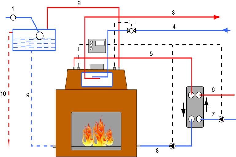
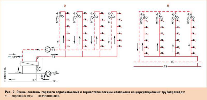
Network heaters
Purpose and connection schemes
Mains heaters are used for heating the mains water turbine bleed steam used for heating, ventilation and hot water supply to consumers.
Scheme of heat supply from the T-250–240 turbine unit: 1 - network pump of the first rise; 2 - stuffing box heater; 3, 4 - bottom and top network heaters; 5 - network pump of the second rise; 6 - condensate pumps for network heaters; С - drainage of condensate from salty compartments of heaters and condensate collector
The return network water to the heaters is supplied by one of two network pumps of the first lift. Second-lift pumps are installed behind the upper mains heater, supplying mains water either to the mains or preliminarily to the peak boiler. Gate valves installed on the supply water pipelines provide the ability to turn off either both network heaters or only the upper one by water. There are also bypasses (500 mm in diameter) that allow smooth regulation of the heating water flow through the heaters.
Air from the housing of the upper network heater is discharged into the steam line of the heating steam of the lower one. From the body of which air enters the turbine condenser.
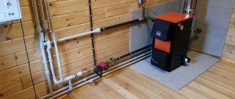
Sequence of actions for self-installation of the system
Arrangement of an open-type heating system implies the sequential performance of the following work:
- Heating boiler installation. Depending on the size, the equipment is securely and firmly fixed to the floor or fixed to the wall.
- Pipe routing. The pipeline is installed in accordance with the previously drawn up project and the selected scheme. At this stage, we must not forget about the recommended slope along the entire contour.
- Installation of heating devices and their connection to a common pipeline.
- Installation of the expansion tank and its thermal insulation (if necessary).
- Connection of system elements.
- Test run, during which places of loose connection are identified.
- Heating system start-up.
It is recommended to install a temperature sensor at the outlet of the boiler, with the help of which the efficiency of the open-type heat supply system is monitored.
Features of systems with forced circulation of the coolant
For high-quality and efficient operation of the forced circuit of an open-type heating system with a pump, the installation of appropriate equipment is required. In this case, it is necessary to correctly select the pump and the place for its installation.
How does a dead-end heating system work?
A dead-end circuit is a two-pipe room heating device, in which, as can be seen from the figure above, the hot coolant is supplied to each radiator through one pipe (supply), and leaves the radiators and enters the boiler through another pipe (return). Moreover, in this scheme, the movement of the coolant along the supply and return pipes occurs in the opposite direction, while in other (not one-pipe) schemes, the liquid moves in one direction. This is a very common option for connecting heating devices, and not only radiators - it can be cast iron or bimetallic batteries, or homemade registers.
Although one-pipe heating can be implemented according to a dead-end scheme, this solution is unpopular due to its low efficiency of heat transfer and the complexity of execution. The implementation of a dead-end one-pipe scheme is shown below - if the house is designed for 2 or three floors, then, in addition to the standard security group, you will have to do the distribution of risers, and install an air vent or Mayevsky valve on each radiator. This is a costly scheme and is therefore rarely accepted for execution.

An indirect advantage of the dead-end scheme is also that it can be used both for heating with forced circulation of the coolant and for solving with the gravitational movement of fluid in pipes. For non-volatile heating of a private house, the system with natural circulation is gaining more and more popularity, so do not forget about the dead-end scheme with the upper piping in this case.
In any case, with a single-circuit or double-circuit scheme, for a dead-end version, the following is obvious: the more radiators are connected to the pipe, the slower all subsequent heating devices will warm up. Therefore, it is advisable to divide the entire system into several branches so that each branch contains no more than 5-6 radiators. This solution is relevant for both natural and forced movement of the coolant.
In practice, the advantage of a dead-end scheme is obvious: these are simple calculations, an uncomplicated level of installation, the minimum number of valves and fittings, and the low cost of the entire project. If we compare with such popular solutions as a two-pipe system with a passing fluid movement and with a beam scheme (with a collector), then in terms of observance of the laws of hydraulics, they are clearly better than a dead end - the coolant moves faster, there is no oncoming traffic, the radiators warm up evenly and at the same speed. But often it is the economy of the dead-end option that wins, especially for heating a house with a small total heated area.
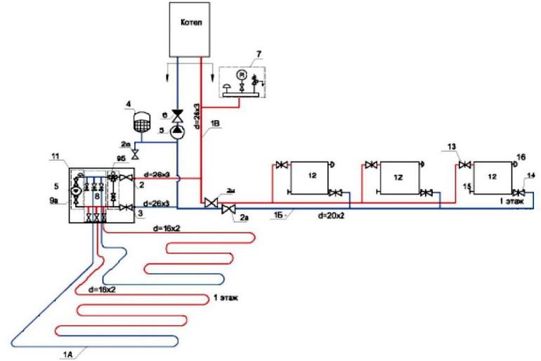
A horizontal dead-end wiring scheme has a version where a central highway is used. Such a scheme can be implemented as a pipeline hidden in the floor or in the wall, which is liked by all homeowners without exception, since the hidden pipeline does not require design redesign, redevelopment or changes in the interior of the premises.
When installing a hidden pipeline, for example, when embedding pipes in a concrete floor screed or in grooves in walls, pipes should be used not steel, but metal-plastic without joints or polymer with a fixed sleeve connection or welding in order to prevent the possibility of leakage. The only problem when laying a hidden pipeline is its correct and beautiful exit from the wall or from under the floor. You should also avoid any crossings of pipes in a flush-mounted installation. To avoid intersections, use a crosspiece. When connecting the pipe to the radiator using a cross, it is possible to go around the pipes of the central line without protruding beyond the mounting plane.
Also, the implementation of a dead-end system with a central highway opens up opportunities for connecting to heating and other schemes: a "warm floor" system or heated towel rails. Such units are connected with the help of a special mixing module, which includes a circulation pump, mixing taps and temperature sensors. The mixing module makes the operation of the plug-in modules independent of the main heating circuit, and any number of new plug-in circuits will not affect the operation of the main circuit.
Pump selection rules
The device is chosen according to two main characteristics: power and head. These parameters directly depend on the area of the heated building. In most cases, the following values are taken as a reference point:
- For a system heating an area of 250 m2, a pump with a capacity of 3.5 m3 / h and a pressure of 0.4 atmospheres is required.
- For an area up to 350 m2, it is better to choose equipment with a capacity of 4.5 m3 / h and a pressure of 0.6 atm.
- If the building has a large area, up to 800 m2, then it is recommended to use a pump with a capacity of 11 m3 / h with a pressure of more than 0.8 atmospheres.
If you more carefully approach the choice of pumping equipment, then additional parameters are taken into account:
- Pipeline length.
- The type of heating devices and their number.
- The diameter of the pipes and the material from which they are made.
- Heating boiler type.
Pump connection to the heating circuit
It is recommended to install the circulation pump on the return pipe, in this case, the already cooled liquid will pass through the device. However, when using more modern models, which are made of heat-resistant materials, a tie-in to the supply line is not excluded. In any case, the installed equipment should not disturb the circulation of the coolant.
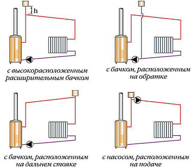
There are several options for changing the gravitational scheme to a forced option:
- Installing the expansion tank at a higher level. This option can be called the simplest, but this will require a high attic space.
- The expansion tank is transferred to the distant riser. If you use this method to reconstruct an old system, it will take a lot of time and effort. If you equip a new system according to this scheme, then it will not justify itself.
- Placing the riser of the expansion tank in close proximity to the elbow on which the pump is located. In this case, the pipe with the reservoir is cut from the supply line and cut into the return pipe behind the pump.
- Pump connection into the supply line. This method is considered the best option for the reconstruction of the heating circuit. Keep in mind, however, that not every appliance can withstand high temperatures.
In order for the heating system with an open expansion tank and pump to work efficiently, it is important to choose the right circuit, calculate the parameters of all the constituent elements, select the appropriate equipment and consistently carry out the installation work.