Characteristic
The most common is precisely the two-pipe heating organization, despite some of the advantages of single-pipe structures. No matter how complex such a line with two pipes (separately for the supply of water and its return) is, the majority prefers it.
Such systems are installed in multi-storey and apartment buildings.
Device
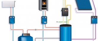
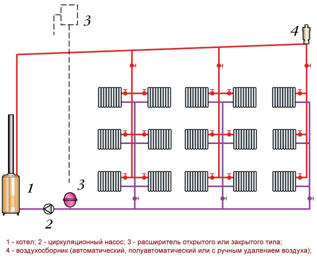
The elements of two-line heating with a bottom pipe cut are as follows:
- boiler and pump;
- auto air vent, thermostatic and safety valves, valves;
- batteries and expansion tank;
- filters, regulating devices, temperature and pressure sensors;
- bypasses can be used, but not required.
Advantages and disadvantages
The considered two-pipe connection scheme, when used, reveals many advantages. Firstly, the uniformity of heat distribution along the entire line and the individual supply of the coolant to the radiators.
Therefore, it is possible to regulate the heating devices separately: turn on / off (you only need to close the riser), change the pressure.
Different rooms can be set to different temperatures.
Secondly, such systems do not require shutting down or draining the entire coolant in the event of a breakdown of one heating device. Thirdly, the system can be installed after the construction of the lower floor and not wait until the whole house is ready. In addition, the piping has a smaller diameter than a single pipe system.
There are also some disadvantages:
- more materials are required than for a single-pipe line;
- the low pressure in the supply riser makes it necessary to frequently bleed air by connecting additional valves.
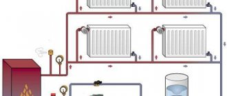
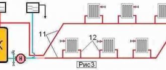
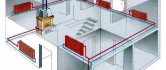
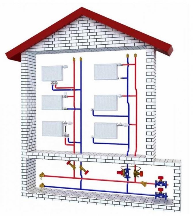
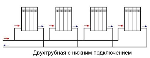
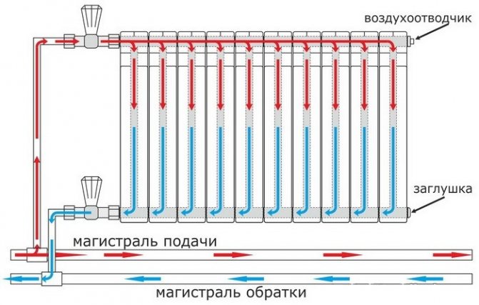
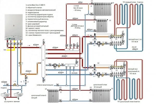
How does a two-pipe system with bottom connection work?
The name "two-pipe" comes from the principle of connecting heating pipes: the working fluid enters and is fed back through different lines. Parallel connection of the batteries ensures maximum efficiency of heat transfer and movement of the coolant. If the scheme is implemented in a multi-storey building, then the apartments are heated using a manifold, which facilitates the connection and regulation of the temperature in each individual radiator. The same principle is used in a private house with several floors or a complex heating scheme. A diagram of a two-pipe heating system with a lower wiring is being carried out in the presence of complex monitoring and control equipment, therefore it is not suitable for one-story and small houses.
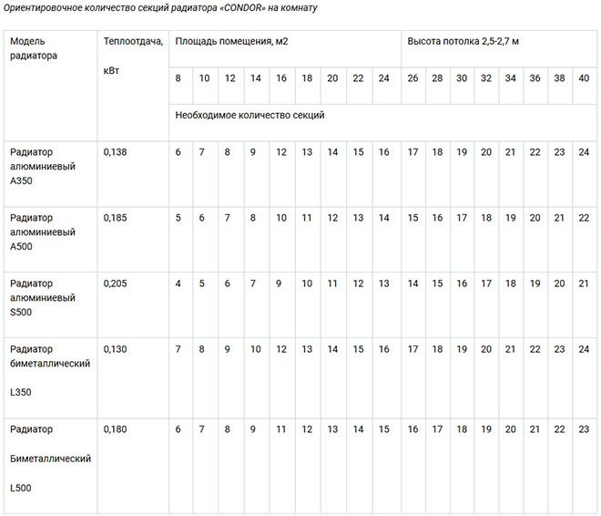
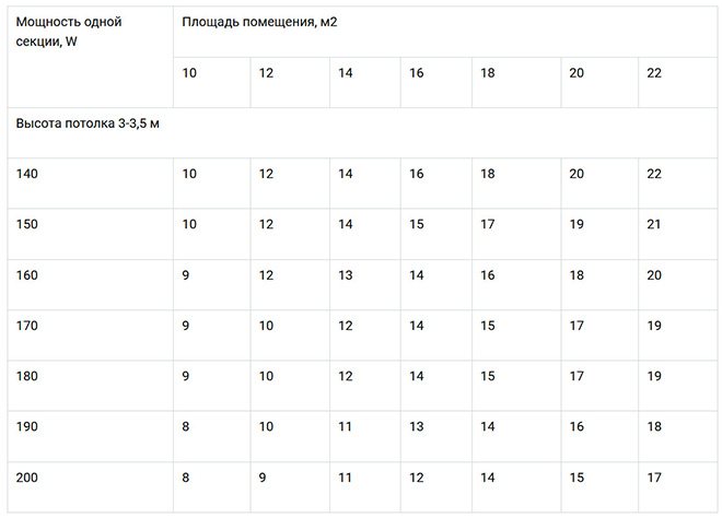
The table shows the results of an approximate calculation of the number of radiator sections for one heated room:
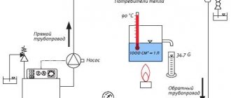
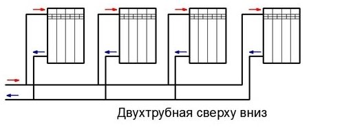
The operation of a heating system with an upper distribution and with a lower pipe connection differs, first of all, in the direction of movement of the working fluid. In a two-pipe scheme, the supply runs parallel to the return, at the bottom, and the heated working fluid flows along the main riser in the direction from bottom to top. As it moves, the coolant, passing through the heating radiators, moves along the return pipes and enters the boiler. Air locks that invariably arise in any scheme are released by opening the Mayevsky taps installed on all batteries or radiators. Instead of Mayevsky's taps, automatic valves are installed - air vents.
The table below shows data on calculating the power of radiators depending on the heated area of the room:
Any scheme of two-pipe distribution of heating pipes with a bottom connection has one or more heating circuits through which the liquid flows along the supply and return path. If the supply pipe is laid at the level of the radiator or below, then the appearance of air in the system is practically guaranteed, therefore, Mayevsky taps should be on every floor, even if it is a one-story building. You can also remove air from the system in another way: lay separate air lines next to the heating route, included in the wiring, and connected at the outlet to the expansion tank.
In this case, Mayevsky's cranes or air vents are not needed, but the air routes significantly complicate the layout and the practical side of the wiring - the possibility of attaching pipes, turns and placement of additional routes along the walls or floor, which makes such a structure cumbersome and voluminous. In addition, connecting pipes for overhead lines is the placement of floor-to-ceiling risers in each room, which negates all the advantages of bottom connection.
Comparison with other types
In the lower inset, the supply line is laid from the bottom, next to the return, because the coolant is directed from the bottom up along the supply risers. Both types of wiring can be designed with one or more circuits, dead-end and associated water flow in the supply pipe and return.
Natural circulation systems with a bottom line are very rarely used, since they require a large number of risers, and the point of such a pipe tie is to reduce their number to a minimum. With this in mind, such designs most often have forced circulation.
Roof and floors - meaning
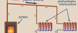
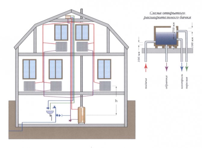
In the upper connection, the supply line is above the radiator level. It is installed in the attic, in the ceiling. The heated water enters the top, then - through the supply risers, it evenly spreads over the batteries. Radiators should be located above the return line. To exclude air accumulation, a compensating tank is mounted at the very top point (in the attic). Therefore, it is not suitable for flat roof houses without an attic.
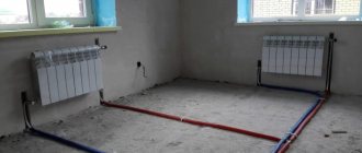
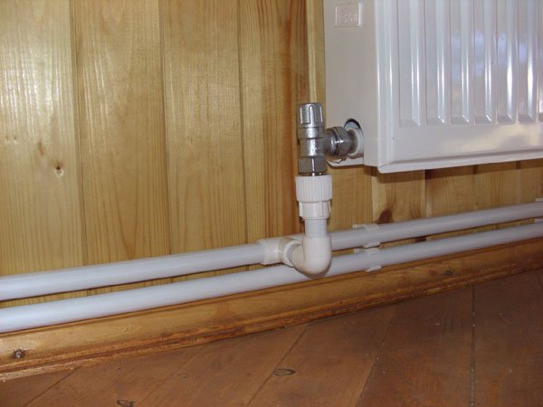
The wiring from the bottom has two pipes - supply and outlet, - the radiators must be higher than them. It is very convenient for removing air locks with Mayevsky taps. The supply line is located in the basement, in the plinth, under the floor. The supply line must be higher than the return. The additional slope of the line towards the boiler minimizes air pockets.
Both wiring is most effective in a vertical configuration where the batteries are mounted on different floors or levels.
Radiators for centralized heating systems
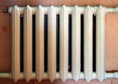
Columnar cast iron radiator
- Many of us have long been accustomed to cast-iron radiators installed from the moment the house was built and even, if the need arises, replace them with similar ones. For centralized heating systems, such batteries are good enough, because they can withstand high pressure, so the battery has two numbers in the passport, the first of which indicates the working pressure, and the second is the pressure (test) pressure. For cast iron appliances, this is usually 6/15 or 8/15.
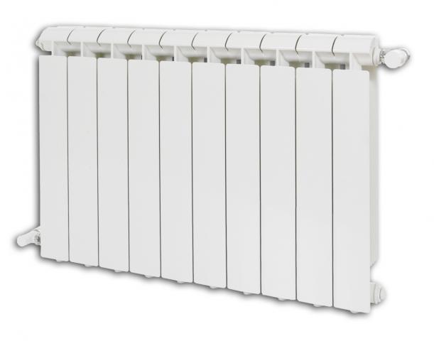
Sectional bimetallic radiator
- But in a nine-story building, the working pressure usually reaches 6 atmospheres, so the above-described batteries are quite suitable, but in a 22-story building, the pressure can reach 15 atmospheres, so devices made of steel or bimetal are more appropriate here. Only aluminum radiators are not suitable for centralized heating, since they will not withstand the operating state of the centralized circuit.
Recommendations. If you have started a major overhaul in your apartment and also want to replace the radiators, then, if possible, replace the wiring pipes.These ½ ”or ¾” pipes are probably not in very good condition either, and an ecoplast would be better used instead. Steel and bimetallic (sectional or panel) radiators have narrower watercourses than cast iron ones, so they can become clogged and lose power. To prevent this from happening, put a regular filter on the water supply to the battery, which is installed in front of the water meter.
Principle of operation
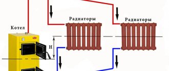
The main characteristic of a two-pipe system is the presence of an individual water supply line to each radiator. In this scheme, each of the batteries is equipped with two separate pipes: water supply and outlet. The coolant flows to the batteries from the bottom up. The cooled water returns through the return risers to the return line, and through it to the boiler.
In a multi-storey room, it is appropriate to install exactly a two-pipe structure with a vertical line and lower wiring. In this case, the temperature difference between the heating medium in the supply pipe and the return pipe creates a strong pressure that increases as the floor rises. The pressure helps the water move through the pipeline.
In the considered lower pipe connection, the boiler must be in a recess, since the batteries and heating devices must be higher to ensure uniform delivery of water to them.
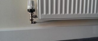
The air that accumulates is removed by Mayevsky taps or drains, they are mounted on all heating devices. Automatic dumpers are also used, which are fixed on risers or special air vent lines.
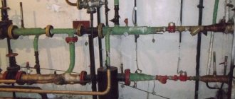
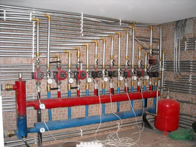
Piping layout
While heating engineers are discussing the optimal heating scheme for a central heating house, the issue of competent piping in the house is being raised. In modern multi-storey buildings, the heating wiring diagram can be implemented according to one of two possible patterns.
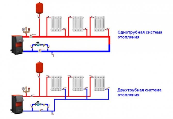
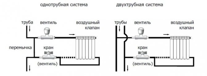
One pipe connection
The first template provides for a one-pipe connection with top or bottom wiring and is the most used option when equipping multi-storey buildings with heating devices. At the same time, the location of the return and supply is not strictly regulated and may vary depending on external conditions - the region in which the house is built, its layout, number of storeys and construction. The direct direction of movement of the coolant along the risers can also change. The option of movement of heated water in the direction from bottom to top or top to bottom is provided.
One-pipe connection is characterized by simple installation, affordable cost, reliability and long service life, but it also has a number of drawbacks. Among them, the loss of temperature of the coolant during movement along the contour and low efficiency indicators.
In practice, various devices can be used in order to compensate for the shortcomings in which a single-pipe heating scheme differs, a radiant system can become an effective solution to the problem. It is designed to use a manifold to help regulate temperature conditions.
Two-pipe connection
The two-pipe connection is the second version of the template. The two-pipe heating scheme of a five-story building (as an example) is devoid of the disadvantages described above, and differs in a completely different design than a one-pipe one. When implementing this scheme, the heated water from the radiator does not move to the next heating device in the circuit, but immediately enters the check valve and is sent to the boiler room for heating. Thus, it is possible to avoid the loss of temperature of the coolant circulating along the contour of a multi-storey building.
The complexity of the connection, which is assumed by the two-pipe connection diagram of the heating battery in the apartment, makes the implementation of this type of heating a long and laborious process that requires large material and physical costs.Maintenance of the system is also not cheap, but the high cost is compensated by high-quality and uniform heating of the house on all floors.
Among the advantages that a two-pipe circuit for connecting heating batteries gives, it is worth highlighting the possibility of installing a special device on each radiator in the circuit - a heat meter. It allows you to control the temperature of the coolant in the battery, and using it in the apartment, the owner will achieve significant results in saving money on utility bills, because he will be able to independently regulate the heating if necessary.
Views
A two-pipe heating system can be of the following types:
- horizontal and vertical;
- straight-through - the coolant flows in one direction through both pipes;
- dead-end - hot and cooled water moves in different directions;
- with forced or natural circulation: for the first, a pump is needed, for the second, the slope of the pipes towards the boiler.
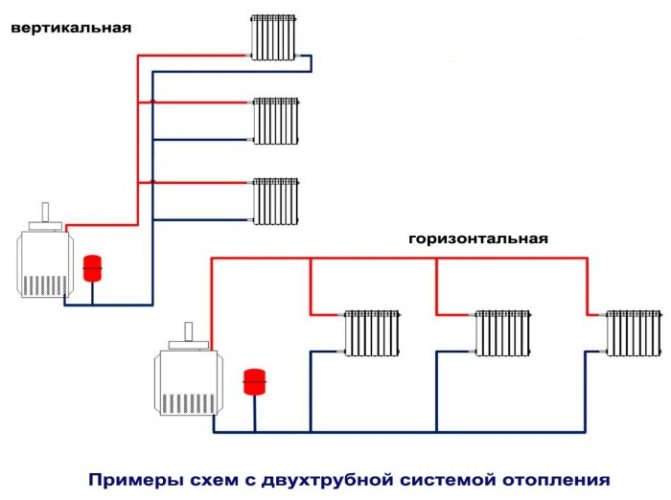
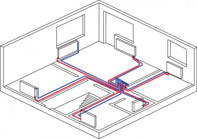
The horizontal scheme can be with dead ends, with passing water movement, with a collector. It is suitable for single-storey buildings with a considerable length, when it is advisable to connect the batteries to a horizontally located main pipe. Such a system is also convenient for buildings without walls, in panel-frame houses, where it is convenient to place the risers on the staircase or corridor.
According to experts, the most effective was the vertical circuit with forced water flow. It needs a pump, which is located on the return line in front of the boiler. An expansion tank is also mounted on it. Due to the pump, the pipes can be smaller than in a design with natural movement: with its help, water will be guaranteed to move along the entire line.
All heaters are connected to a vertical riser. This is the best option for high-rise buildings. Each floor is connected to the riser pipe separately. The advantage is the absence of air pockets.
Installation
Conventionally, several stages of work can be distinguished. First, the type of heating is determined. If gas is supplied to the house, then the most ideal option would be to install two boilers: one - gas, the second - spare, solid fuel or electricity.
Next, you should agree on the installation of the heating system in the project documentation and proceed with the purchase of the necessary materials, devices, and preparation of tools.
Stages
Briefly, the installation consists of the following points:
- the supply pipe is brought up from the boiler and connected to the expansion tank;
- a pipe of the upper line is taken out of the tank, which goes to all radiators;
- a bypass (if provided) and a pump are installed;
- a return line is drawn parallel to the supply line, it is also connected to the radiators and cut into the boiler.
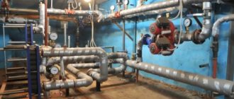
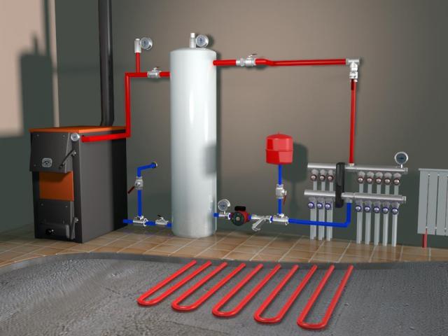
Boiler
For a two-pipe system, the boiler is installed first, for which a mini-boiler room is created. In most cases, this is a basement (ideally a separate room). The main requirement is good ventilation. The boiler must have free access and be located at some distance from the walls.
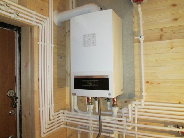
The floor and walls around it are lined with refractory material, and the chimney is led out into the street. If necessary, a pump for circulation, a manifold for distribution, regulating, measuring instruments are installed near the boiler.
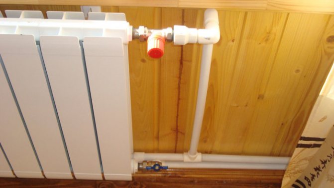
Radiators
They are installed last. They are located under the windows and are fixed with brackets. The recommended height from the floor is 10–12 cm, from the walls - 2-5 cm, from the windowsills - 10 cm. The inlet and outlet of the battery is fixed by locking and regulating devices.
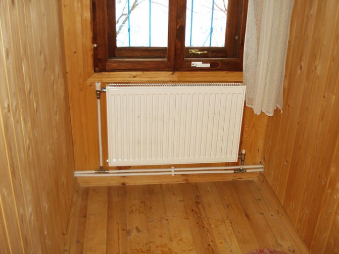
It is advisable to install temperature sensors - they can be used to monitor temperature indicators and regulate them.
If the heating boiler is gas, then it is necessary to have the appropriate documentation and the presence of a representative of the gas industry at the first start.
Accurate calculation of a two-pipe heating system
Before starting work, it is necessary to draw up a heating scheme, decide on the material, and make a hydraulic calculation. It is necessary to calculate the head drop in the back section or to calculate the pipe diameter.
The calculation is carried out taking into account the following factors:
- The inner surface of the pipes and its roughness;
- Section diameter;
- Number of pipe bends;
- Differential pressure between supply and return;
- The number of radiators and their cross-section;
- Locking elements.
To calculate a two-pipe heating system, it is better to turn to professionals
When calculating, use formulas and an axonometric table. You can use a special software program. The most loaded ring or contour is taken as the main object. As a result of calculations, the optimal speed of movement should be between 0.3 and 0.7 m / s.
At a higher speed, the heating will make noise, at a lower speed, a strong temperature variation will occur.
After the calculations, they acquire pipes of an effective diameter, the required number of radiators, a boiler, fittings, squeegees, an expansion tank, a pump for circulation, if there is such a need.
Tips
The expansion vessel is located at or above the highest peak point of the line. If there is an autonomous water supply, then it can be integrated with a supply tank. The slope of the supply and return pipes should be no more than 10 cm by 20 or more linear meters.
If the pipeline is at the front door, it is appropriate to divide it into two elbows. The routing is then created from the top point of the system. The lower line of the two-pipe design must be symmetrical and parallel to the upper one.
All technological units must be equipped with taps, and it is advisable to insulate the supply pipe. It is also advisable to place the distribution tank in an insulated room. In this case, there should be no right angles, sharp fractures, which will subsequently create resistance and air locks. Finally, we must not forget about the pipe supports - they must be made of steel and cut in every 1.2 meters.