Heating system device
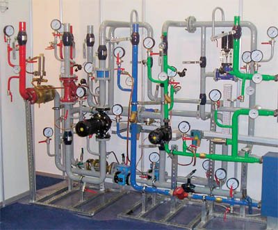
A heating unit is a way of connecting a home heating system to the mains. The structure of a heating unit in a typical apartment building built in the Soviet years includes: a mud sump, shut-off valves, control devices, the elevator itself, etc.
The elevator unit is placed in a separate ITP room (individual heating station). There must certainly be a shut-off valve in order, if necessary, to disconnect the in-house system from the main heat supply. In order to avoid blockages and blockages in the system itself and the devices of the internal house pipeline, it is necessary to isolate the dirt coming along with hot water from the main heating network, for this a mud sump is installed. The diameter of the sump is usually from 159 to 200 millimeters, all incoming dirt (solid particles, scale) collects and settles in it. The sump, in turn, needs timely and regular cleaning.
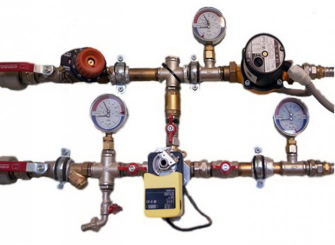
Control devices are thermometers and manometers that measure temperature and pressure in the elevator unit.
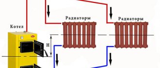
The device and principle of operation of the heating elevator
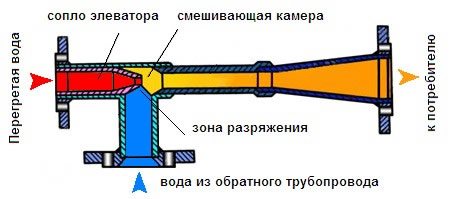
At the entry point of the heating network pipeline, usually in the basement, the knot that connects the supply and return pipes is striking. This is an elevator - a mixing unit for heating a house. The elevator is manufactured in the form of a cast iron or steel structure equipped with three flanges. This is an ordinary heating elevator, its principle of operation is based on the laws of physics. Inside the elevator there is a nozzle, a receiving chamber, a mixing neck and a diffuser. The receiving chamber is connected to the "return" by means of a flange. Superheated water enters the elevator inlet and flows into the nozzle. Due to the narrowing of the nozzle, the flow rate increases and the pressure decreases (Bernoulli's law). Water from the "return" is sucked into the area of reduced pressure and mixed in the mixing chamber of the elevator. The water reduces the temperature to the desired level and at the same time decreases the pressure. The elevator works simultaneously as a circulation pump and a mixer. This is, in brief, the principle of operation of an elevator in the heating system of a building or structure.
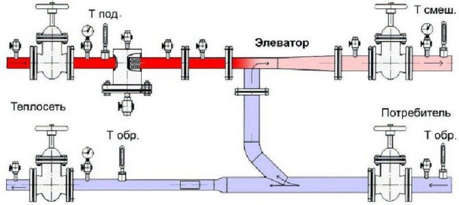
Heating unit diagram
The adjustment of the coolant supply is carried out by the elevator heating units of the house. The elevator is the main element of the heating unit; it needs strapping. The regulating equipment is sensitive to contamination, therefore, mud filters are included in the piping, which are connected to the "supply" and "return".
The elevator trim includes:
- mud filters;
- pressure gauges (inlet and outlet);
- temperature sensors (thermometers at the inlet of the elevator, at the outlet and at the "return");
- gate valves (for preventive or emergency work).
This is the simplest version of the circuit for adjusting the temperature of the coolant, but it is often used as the basic device of the heating unit. The basic unit for elevator heating of any buildings and structures, provides regulation of the temperature and pressure of the coolant in the circuit.
The advantages of using it for heating large buildings, houses and high-rise buildings:
- reliability due to the simplicity of the design;
- low cost of assembly and component parts;
- absolute non-volatility;
- significant savings in heat carrier consumption up to 30%.
But in the presence of indisputable advantages of using an elevator for heating systems, the disadvantages of using this device should also be noted:
- the calculation is done individually for each system;
- you need a mandatory pressure drop in the heating system of the facility;
- if the elevator is not adjustable, it is not possible to change the parameters of the heating circuit.
Elevator with automatic adjustment
Currently, there are elevator designs in which, with the help of electronic adjustment, the nozzle cross-section can be changed. Such an elevator has a mechanism that moves the throttle needle. It changes the lumen of the nozzle and, as a result, the flow rate of the coolant changes. Changing the clearance changes the speed of movement of the water. As a result, the mixing ratio of hot water and water from the "return" changes, thereby changing the temperature of the coolant in the "supply". Now it is clear why water pressure is needed in the heating system.
The elevator regulates the flow and pressure of the heating medium, and its pressure drives the flow in the heating circuit.
The purpose of the elevator in the heating system
The heat carrier leaving the boiler room or CHP plant has a high temperature - from 105 to 150 ° С. Naturally, it is unacceptable to supply water with such a temperature to the heating system.
Regulatory documents limit this temperature to a limit of 95 ° C and here's why:
- for safety reasons: you can get burns from touching the batteries;
- not all radiators can function at high temperatures, not to mention polymer pipes.
The operation of the heating elevator allows the temperature of the supply water to be reduced to the normalized level. You may ask - why can't you immediately send water with the required parameters to the houses? The answer lies in the plane of economic feasibility, the supply of a superheated coolant makes it possible to transfer a much larger amount of heat with the same volume of water. If the temperature is reduced, then it will be necessary to increase the flow rate of the coolant, and then the diameters of pipelines of heating networks will significantly increase.
So, the work of the elevator unit installed in the heating point consists in lowering the water temperature by mixing the cooled coolant from the return line into the supply pipeline. It should be noted that this element is considered obsolete, although it is still widely used today. Now, when installing heat points, mixing units with three-way valves or plate heat exchangers are used.
Why do you need a heating unit
The heating point is located at the entrance of the heating main into the house. Its main purpose is to change the parameters of the coolant. To put it more clearly, the heating unit reduces the temperature and pressure of the coolant before it enters your radiator or convector. This is necessary not only so that you do not burn yourself from touching the heating device, but also to extend the service life of all equipment of the heating system.
This is especially important if the heating inside the house is divorced using polypropylene or metal-plastic pipes. There are regulated operating modes of heating units:
These figures show the maximum and minimum temperature of the coolant in the heating main.
Also, according to modern requirements, a heat meter should be installed at each heating unit. Now let's move on to the design of the heating units.
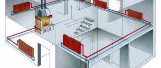
Heating distribution point of the building
Heating engineers recommend using one of three temperature modes of boiler operation. These modes were initially calculated theoretically and have been in practical use for many years. They provide heat transfer with minimal loss over long distances with maximum efficiency.
The thermal modes of the boiler can be designated as the ratio of the supply temperature to the "return" temperature:
- 150/70 - the supply temperature is 150 degrees, and the "return" temperature is 70 degrees.
- 130/70 - water temperature 130 degrees, "return" temperature 70 degrees;
- 95/70 - water temperature 95 degrees, return temperature - 70 degrees.
In real conditions, the mode is selected for each specific region, based on the value of the winter air temperature. It should be noted that it is impossible to use high temperatures for heating rooms, especially 150 and 130 degrees, in order to avoid burns and serious consequences during depressurization.
The water temperature is above the boiling point and it does not boil in the pipes due to the high pressure. This means that it is necessary to reduce the temperature and pressure and provide the necessary heat extraction for a particular building. This task is entrusted to the elevator unit of the heating system - special heating equipment located in the heat distribution point.
Determination of the value of the heating unit
An elevator is a non-volatile independent device that performs the functions of water-jet pumping equipment. The heating unit lowers the pressure, the temperature of the heat carrier, mixing in the chilled water from the heating system.
The equipment is capable of transferring a coolant heated to the highest possible temperatures, which is beneficial from an economic point of view. A ton of water warmed up to +150 C has thermal energy much greater than a ton of coolant with a temperature of only +90 C.
Principles of operation and a detailed diagram of the heating unit
To understand how equipment works, you need to understand its design. The layout of the elevator heating unit is not complicated. The device is a metal tee with connecting flanges at the ends.
The design features are as follows:
- the left branch pipe is a nozzle that tapers towards the end to the calculated diameter;
- behind the nozzle is a cylindrical mixing chamber;
- the lower branch pipe is needed to connect the water reverse circulation pipeline;
- the right branch pipe is an expansion diffuser that transports the hot coolant to the network.
Despite the simple device of the elevator of the heating unit, the principle of operation of the unit is much more complicated:
- The coolant heated to a high temperature moves through the nozzle into the nozzle, then under pressure the transport speed increases, and the water quickly flows through the nozzle into the chamber. The water-jet pump effect maintains a predetermined flow rate of the coolant in the system.
- When water passes through the chamber, the pressure decreases, and the jet passes through the diffuser, providing a vacuum in the mixing chamber. Then, under high pressure, the coolant moves the liquid returned from the heating line through the jumper. The pressure is created by the ejection effect due to the vacuum, which maintains the flow of the supplied heat carrier.
- In the mixing chamber, the temperature regime of the flows decreases to +95 C, this is the optimal indicator for transportation through the heating system of the house.
Understanding what a heating unit in an apartment building is, the principle of operation of an elevator and its capabilities, it is important to maintain the recommended pressure drop in the supply and return pipelines. The difference is necessary to overcome the hydraulic resistance of the network in the house and the device itself
The elevator unit of the heating system is integrated into the network as follows:
- the left branch pipe is connected to the supply line;
- lower - to pipes with return transportation;
- shut-off valves are mounted on both sides, complemented by a dirt filter to prevent blockage of the unit.
The whole circuit is equipped with manometers, heat meters, thermometers. For better flow resistance, a jumper is cut into the return line at an angle of 45 degrees.
Advantages and disadvantages of heating units
A non-volatile heating elevator is inexpensive, does not need to be connected to the power supply, and works flawlessly with any kind of coolant. These properties ensured the demand for equipment in houses with central heating, where a heat carrier of a high degree of heating is supplied.
Disadvantages of using:
- Maintaining the differential pressure of water in the return flow and supply pipelines.
- Each line requires specific calculations and parameters of the heating unit. At the slightest change in fluid temperature, you will have to adjust the nozzle holes, install a new nozzle.
- It is not possible to smoothly regulate the intensity and heating of the transported coolant.
Units with an adjustable bore section, manually or electrically driven by a gear transmission located in the antechamber, are on sale. But in this case the device loses its non-volatility.
Calculation of the heating elevator
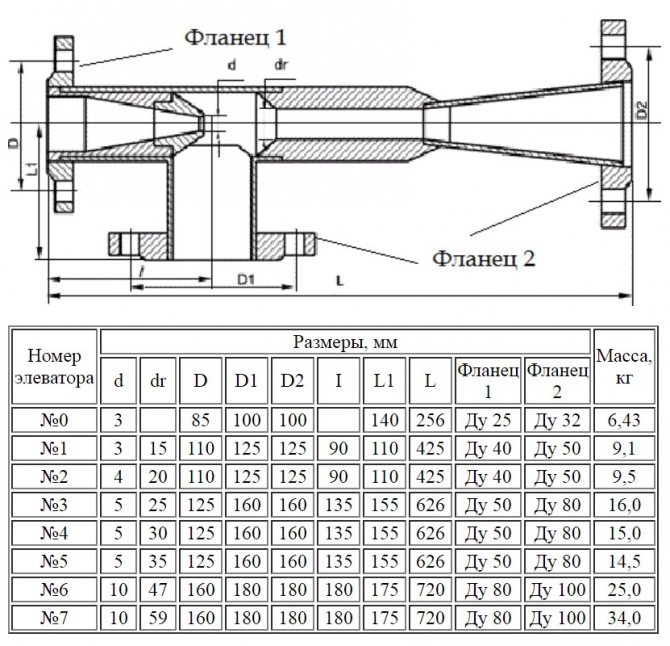
It should be noted that the calculation of a water-jet pump, which is an elevator, is considered rather cumbersome, we will try to present it in an accessible form. So, for the selection of the unit, two main characteristics of the elevators are important to us - the internal size of the mixing chamber and the flow diameter of the nozzle. The size of the chamber is determined by the formula:
- dr is the required diameter, cm;
- Gpr - reduced amount of mixed water, t / h.
In turn, the reduced flow rate is calculated as follows:
In this formula:
- τcm - temperature of the mixture going for heating, ° С;
- τ20 is the temperature of the cooled coolant in the return line, ° С;
- h2 - resistance of the heating system, m. water. Art .;
- Q is the required heat consumption, kcal / h.
To select the elevator unit of the heating system according to the size of the nozzle, you need to calculate it using the formula:
- dr is the diameter of the mixing chamber, cm;
- Gпр - reduced consumption of mixed water, t / h;
- u is the dimensionless injection (mixing) coefficient.
The first 2 parameters are already known, it remains only to find the value of the mixing ratio:
In this formula:
- τ1 is the temperature of the superheated coolant at the inlet to the elevator;
- τcm, τ20 - the same as in the previous formulas.
Note.
To calculate the nozzle, you need to take the coefficient u equal to 1.15u '.
Based on the results obtained, the unit is selected according to two main characteristics. The standard sizes of elevators are designated by numbers from 1 to 7, it is necessary to take the one that is closest to the design parameters.
The main malfunctions of the elevator unit
Even a device as simple as an elevator unit can malfunction. Malfunctions can be determined by analyzing the readings of the manometers at the control points of the elevator unit:
- Malfunctions are often caused by clogging of pipelines with dirt and solid particles in the water. If there is a drop in pressure in the heating system, which is much higher up to the sump, then this malfunction is caused by clogging of the sump, which is in the supply pipeline. The dirt is discharged through the drain channels of the sump, cleaning the nets and internal surfaces of the device
- If the pressure in the heating system jumps, then possible causes may be corrosion or a clogged nozzle. If the nozzle breaks down, the pressure in the heating expansion vessel may exceed the permissible value.
- A case is possible in which the pressure in the heating system rises, and the manometers before and after the sump in the "return" show different values. In this case, you need to clean the "return" sump. The drain taps on it are opened, the mesh is cleaned, and dirt is removed from the inside.
- When the size of the nozzle changes due to corrosion, a vertical misalignment of the heating circuit occurs. The batteries will be hot at the bottom, and insufficiently heated on the upper floors. Replacing the nozzle with a nozzle with a calculated diameter will eliminate this problem.
What is an elevator heating unit and what is it used for?
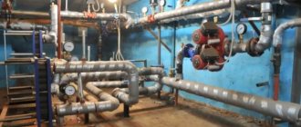
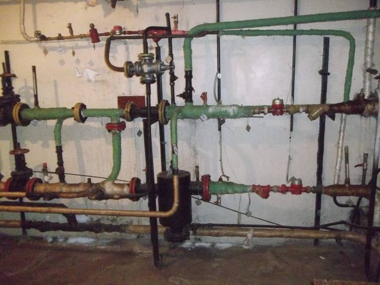
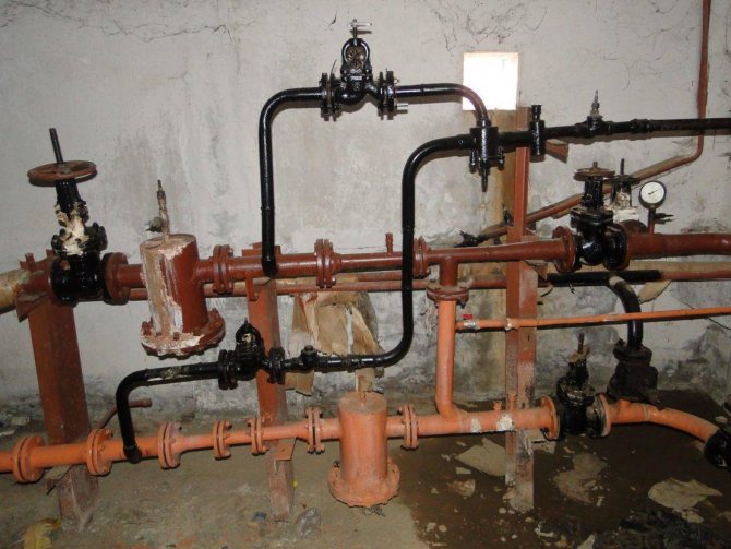
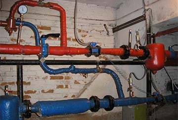
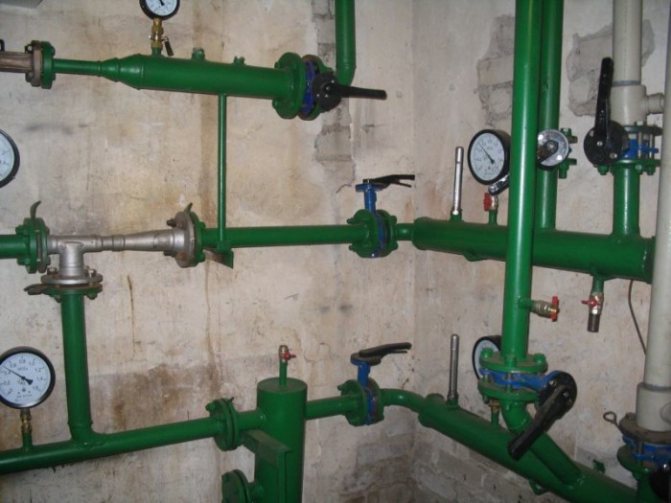
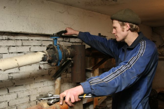
In order to clearly understand the structure and purpose of the elevator unit, you can go into an ordinary basement of a multi-storey building. There, among the rest of the elements of the heating unit, you can find the desired part.
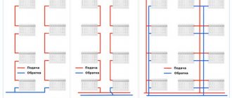
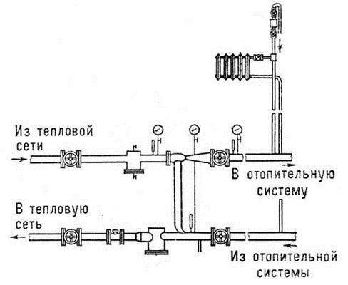
Consider a schematic diagram of the supply of coolant to the heating system of a residential building. Hot water is piped to the house. It should be noted that there are only two pipelines, of which:
- 1 - supply (brings hot water to the house);
- 2 - reverse (carries out the removal of the coolant that has given off heat back to the boiler room);
The water heated to a certain temperature from the heat chamber enters the basement of the building, where stop valves are installed at the entrance to the heating unit on pipelines. Previously, gate valves were widely installed as shut-off valves, now they are gradually being replaced by ball valves made of steel. The further path of the coolant depends on its temperature.
In our country, boiler houses operate in three main thermal modes:
- 95 (90) / 70 ° C;
- 130/70 0 C;
- 150/70 0 C;
If the water in the supply pipeline is heated to no more than 95 0 С, then it is simply distributed through the heating system using a collector equipped with adjusting devices (balancing valves). In the event that the temperature of the coolant is higher than 95 0 С, then according to the current standards, such water cannot be supplied to the heating system. We need to cool it down. This is where the elevator unit comes into operation. It should be noted that the elevator heating unit is the cheapest and easiest way to cool the coolant.
Wiring diagrams for the elevator unit of the heating system
The processes of heating water for hot water supply (DHW) and heating systems are in some way interconnected with each other.
Due to the fact that the temperature of the water in the hot water supply under any conditions must be maintained within the range of 60 - 65 degrees, at positive outside temperatures, a hotter coolant can enter the elevator than required.
In this case, there is an overconsumption of heat at the level of 5% - 13%. To avoid this phenomenon, three schemes for connecting the elevator unit are used:
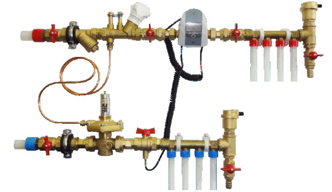
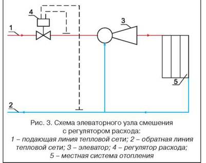
- with a water flow regulator;
- with an adjustable nozzle;
- with a regulating pump.
With water flow regulator
When this condition is met, it is possible to avoid floor misalignment, which occurs in single-pipe systems in the event of a decrease in the flow rate of the coolant.
However, the elevator + flow regulator is not able to maintain the temperature downstream of this device at an acceptable level when there are deviations from the normal temperature schedule.
With adjustable nozzle
The cross-sectional area of the nozzle outlet is regulated by a needle inserted into it. At the same time, the mixing ratio increases and, accordingly, the temperature of the coolant after the elevator decreases.
The disadvantage of this scheme is that when the needle is inserted into the hole of the cone, the hydraulic resistance of the latter increases, as a result of which the flow rate of the coolant, and, accordingly, the amount of supplied heat, decreases.
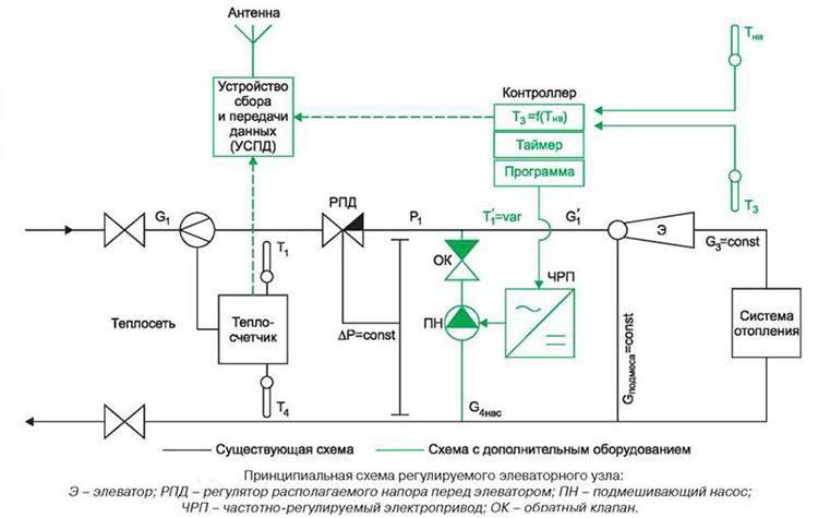
Schematic diagram of an adjustable elevator unit
With control pump
The pump is mounted on the mixing line of the elevator unit or parallel to it. In addition to it, regulators of the heat carrier flow and its temperature are mounted. This solution is very effective because it allows you to:
- regulate the temperature of the coolant at any outside temperature, and not only at positive;
- maintain the circulation of the coolant in the internal network when the external network is stopped.
The disadvantages of the scheme include high cost, complexity and increased operating costs due to the power supply of the pump.
Possible problems and malfunctions
Despite the durability of the devices, sometimes the elevator heating unit malfunctions. Hot water and high pressure quickly find weak points and provoke breakdowns.
This inevitably happens when individual assemblies are of poor quality, the calculation of the nozzle diameter is incorrect, and also due to the formation of blockages.
Noise
The heating elevator can generate noise when operating. If this is observed, it means that cracks or scuffs have formed in the outlet of the nozzle during operation.
The reason for the appearance of irregularities lies in the distortion of the nozzle caused by the supply of a coolant under high pressure. This happens if the excess head is not throttled by the flow regulator.
Temperature mismatch
The quality operation of the elevator can be questioned even when the temperature at the inlet and outlet is too different from the temperature schedule. This is most likely due to the oversized nozzle diameter.
Incorrect water flow
A defective throttle will result in a change in water flow from the design value.
Such a violation can be easily identified by the change in temperature in the incoming and outgoing piping systems. The problem is solved by repairing the flow regulator (throttle).
Defective structural elements
If the scheme for connecting the heating system to the external heating main has an independent form, then the reason for the poor-quality operation of the elevator unit can be caused by faulty pumps, water heating units, shut-off and safety valves, all kinds of leaks in pipelines and equipment, malfunctioning regulators.
The main reasons that negatively affect the circuit and the principle of operation of pumps include the destruction of elastic couplings in the joints of the pump and electric motor shafts, wear of ball bearings and destruction of seats for them, the formation of fistulas and cracks on the body, aging of oil seals. Most of the faults listed can be fixed by repair.
The problem of fistulas and cracks in the case is solved by replacing it.
Unsatisfactory operation of water heaters is observed when the tightness of the pipes is broken, their destruction occurs or the tube bundle sticks together. The solution to the problem is to replace the pipes.
Blockages
Blockages are one of the common causes of poor heat supply. Their formation is associated with the ingress of dirt into the system when the dirt filters are faulty. Increase the problem and build up of corrosion products inside the pipes.
The level of clogging of the filters can be determined by the readings of the pressure gauges installed in front of the filter and after it. A significant pressure drop will confirm or disprove the assumption about the degree of debris. To clean the filters, it is enough to drain the dirt through the drain devices located in the lower part of the housing.
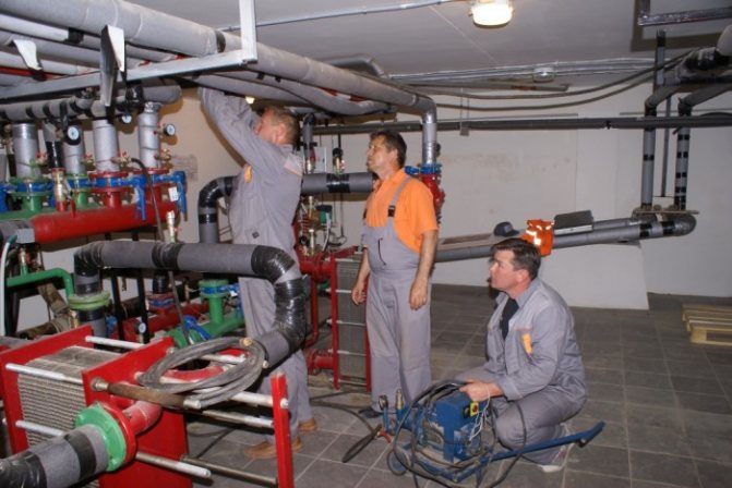
Any malfunctions of pipelines and heating equipment must be eliminated immediately.
Minor remarks that do not affect the operation of the heating system are mandatory registered in special documentation, they are included in the plan for current or major repairs. Repair and elimination of comments occurs in the summer before the start of the next heating season.
DHW from an individual heating point
The simplest and most common is the scheme with a single-stage parallel connection of hot water heaters (Fig. 10). They are connected to the same heating network as the heating systems of the buildings. Water from the external water supply network is supplied to the DHW heater. In it, it is heated by network water coming from a heat source.
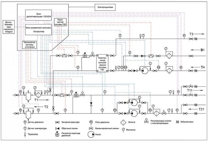
Fig. 10. Scheme with dependent connection of the heating system to the external network and single-stage parallel connection of the DHW heat exchanger
The cooled network water is returned to the heat source.After the hot water supply heater, the heated tap water enters the DHW system. If the devices in this system are closed (for example, at night), then hot water is fed back to the DHW heat exchanger through the circulation pipe.
In addition, a two-stage hot water heating system is used. In it, in winter, cold tap water is first heated in the first stage heat exchanger (from 5 to 30 ° C) with a coolant from the return pipe of the heating system, and then water from the supply pipe of the external network is used for the final heating of the water to the required temperature (60 ° C) ... The idea is to use waste heat energy from the return line from the heating system for heating. At the same time, the consumption of network water for heating water in the hot water supply is reduced. In the summer, heating takes place according to a one-stage scheme.
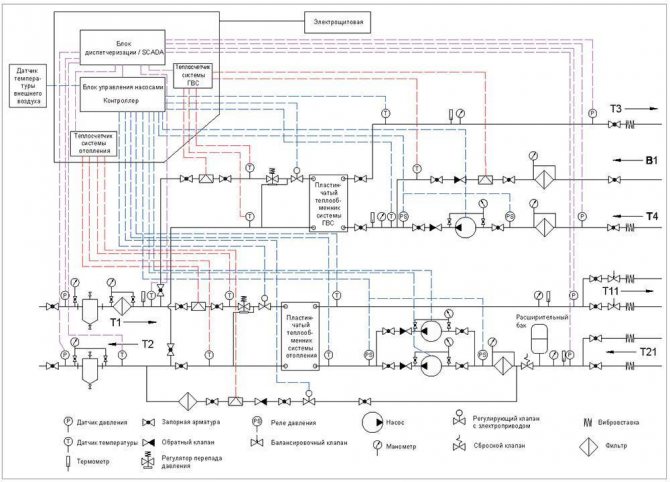
Fig. 11. Diagram of an individual heating point with independent connection of the heating system to the heating network and parallel connection of the DHW system
For multi-storey high-rise (more than 20 storeys) housing construction, schemes with independent connection of the heating system to the heating network and parallel connection of hot water supply are mainly used (Fig. 11). This solution allows you to divide the heating and hot water supply systems of the building into several independent hydraulic zones, when one IHP is in the basement and ensures the operation of the lower part of the building, for example, from the 1st to the 12th floor, and on the technical floor of the building there is exactly the same heating point for 13 - 24 floors. In this case, heating and DHW are easier to regulate in the event of a change in heat load, and also have less inertia in terms of hydraulic mode and balancing.
Purpose and characteristics
The heating elevator cools the overheated water to the design temperature, after which the treated water enters the heating devices that are located in the living quarters. Water cooling occurs when hot water from the supply pipe is mixed in the elevator with cooled water from the return.
Schematic diagram of the elevator unit
The heating elevator diagram clearly shows that this unit contributes to an increase in the efficiency of the entire heating system of the building. It is entrusted with two functions at once - a mixer and a circulation pump. Such a node is inexpensive, it does not require electricity. But the elevator also has several disadvantages:
- The pressure drop between the direct and return lines must be between 0.8-2 bar.
- The output temperature cannot be adjusted.
- There must be an accurate calculation for each component of the elevator.
Elevators are widely used in the communal heating sector, since they are stable in operation when the thermal and hydraulic regime changes in heating networks. The heating elevator does not need to be constantly monitored, all regulation consists in choosing the correct nozzle diameter.
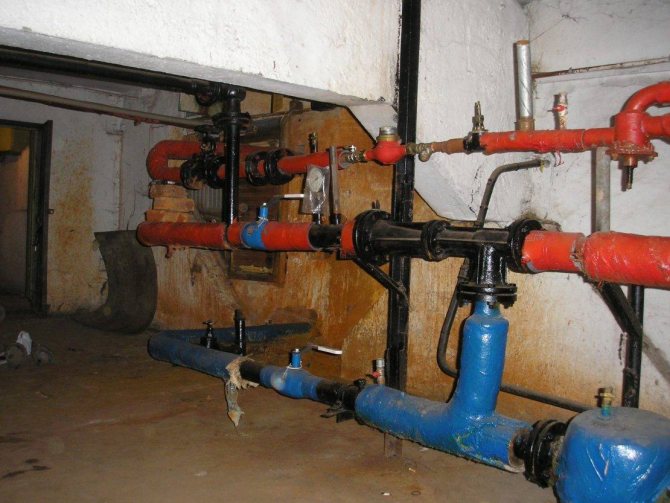
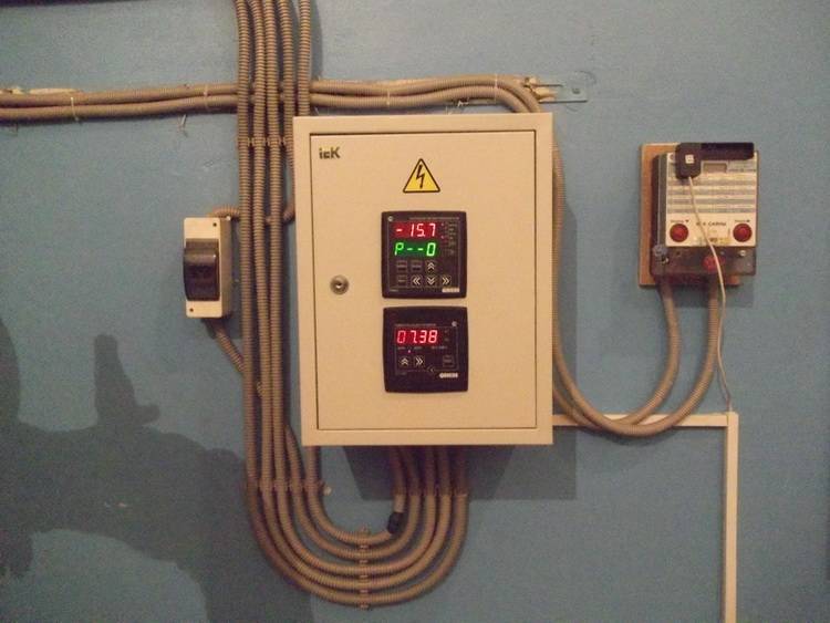
Elevator unit in the boiler room of an apartment building
The heating elevator consists of three elements - a jet elevator, a nozzle and a vacuum chamber. There is also such a thing as elevator strapping. The necessary shut-off valves, control thermometers and pressure gauges must be used here.
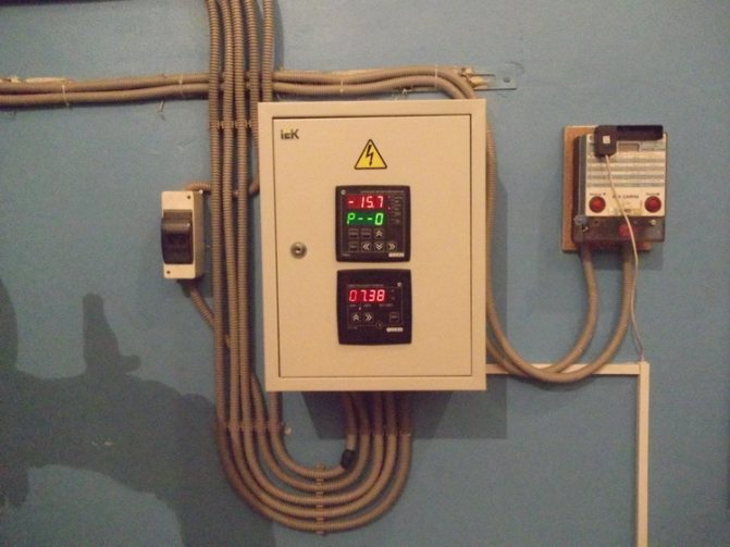
Today you can find elevator units of the heating system, which can adjust the diameter of the nozzle with an electric drive. So, it will be possible to automatically regulate the temperature of the heat carrier.
The selection of a heating elevator of this type is due to the fact that here the mixing ratio varies from 2 to 5, in comparison with conventional elevators without nozzle regulation, this indicator remains unchanged. So, in the process of using elevators with an adjustable nozzle, you can slightly reduce heating costs.
Elevator structure
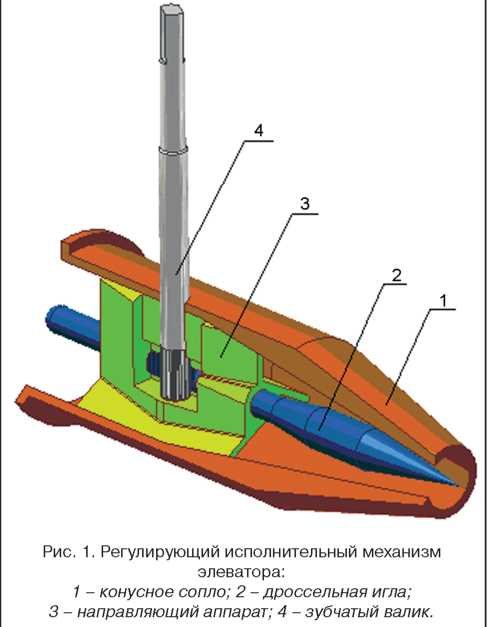
The design of this type of elevators includes a regulating actuator, which ensures the stability of the heating system at low consumption of network water. The cone-shaped nozzle of the elevator system houses a regulating throttle needle and a guide device, which swirls the water stream and acts as a throttle needle shroud.
Storage tank for the heating system
This mechanism has a toothed roller rotating from an electric drive or manually. It is designed to move the throttle needle in the longitudinal direction of the nozzle, change its effective section, after which the water flow rate is regulated. So, it is possible to increase the flow rate of heating water from the calculated indicator by 10-20%, or reduce it to almost complete closure of the nozzle. A decrease in the nozzle cross-section can lead to an increase in the flow rate of the network water and the mixing ratio. This reduces the temperature of the water.
Heating Elevator Unit Actuator
The principle of operation of centralized heating
The general scheme is quite simple: a boiler room or a CHP plant heats water, supplies it to the main heat pipes, and then to heating points - residential buildings, institutions, and so on. When moving through the pipes, the water cools somewhat and at the end point its temperature is lower. To compensate for the cooling, the boiler room heats the water to a higher value. The amount of heating depends on the outside temperature and the temperature schedule.
For example, with a 130/70 schedule at an outside temperature of 0 C, the parameter of the water supplied to the main line is 76 degrees. And at -22 C - not less than 115. The latter fits well into the framework of physical laws, since the pipes are a closed vessel, and the coolant moves under pressure.
It is obvious that such overheated water cannot be supplied to the system, since the overheating effect arises. At the same time, the materials of pipelines and radiators wear out, the surface of the batteries overheats up to the risk of burns, and plastic pipes, in principle, are not designed for a coolant temperature above 90 degrees.
For normal heating, several more conditions must be met.
- First, the pressure and speed of movement of the water. If it is small, then overheated water is supplied to the nearest apartments, and too cold water is supplied to the distant ones, especially the corner ones, as a result of which the house is heated unevenly.
- Secondly, a certain volume of coolant is required for proper heating. The heating unit receives about 5–6 cubic meters from the mains, while the system requires 12–13.
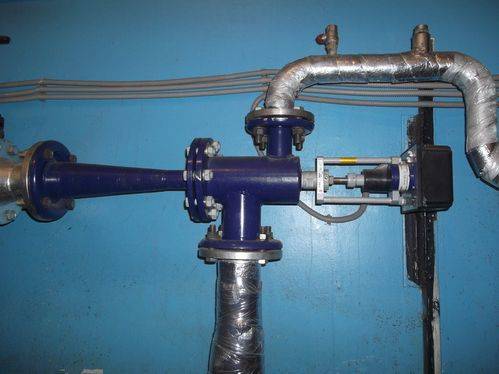
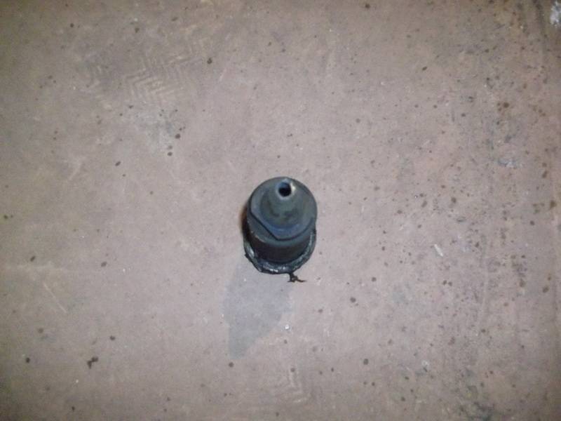
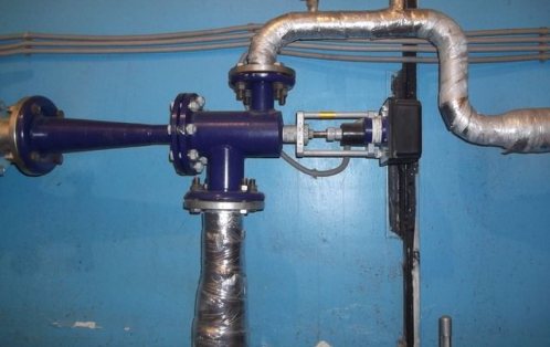
It is for the solution of all of the above issues that the heating elevator is used. The photo shows a sample.
The principle of operation of the elevator unit
The mixing elevator serves as a device for cooling the superheated water received from the heating system to a standard temperature, before supplying it to the in-house heating system. The principle of its lowering consists in mixing water of elevated temperature from the supply pipeline and cooled down from the return pipeline.
The elevator consists of several main parts. This is a suction manifold (inlet from the supply), a nozzle (throttle), a mixing chamber (the middle part of the elevator, where two flows are mixed and the pressure is equalized), a receiving chamber (mixing from the return), and a diffuser (outlet from the elevator directly to the network with a steady pressure ).
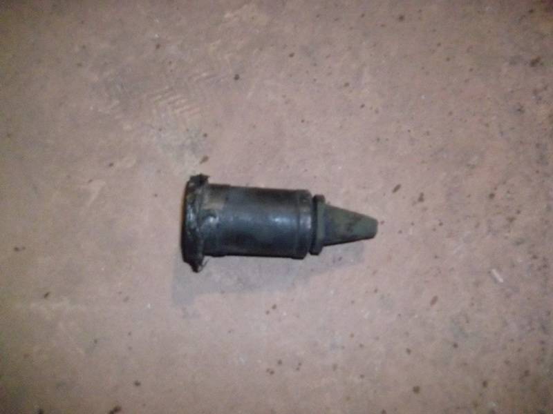
The nozzle is a constriction device located in the steel body of the elevator device. From it, hot water at high speed and with reduced pressure enters the mixing chamber, where water is mixed from the heating network and the return pipeline by suction.In other words, hot water from the main heating network enters the elevator, in which it passes through the converting nozzle at high speed and already reduced pressure, mixes with water from the return pipeline, and then, at a lower temperature, moves into the building pipeline. How the nozzle of a mechanical elevator looks directly can be seen in the photo below.

This structure of the elevator has an actuator to ensure its stable performance, consisting of a guiding device and a throttle needle, which is driven by a toothed roller. The action of the throttle needle regulates the flow rate of the coolant.
How does an elevator work?
In simple terms, an elevator in a heating system is a water pump that does not require external energy supply. Thanks to this, and even the simple design and low cost, the element found its place in almost all heating points that were built in Soviet times. But for its reliable operation, certain conditions are required, which will be discussed below.
To understand the structure of the elevator of the heating system, you should study the diagram shown in the figure above. The unit is somewhat reminiscent of an ordinary tee and is installed on the supply pipeline, with its side outlet it joins the return line. Only through a simple tee would the water from the network go directly into the return pipeline and directly into the heating system without reducing the temperature, which is unacceptable.
A standard elevator consists of a supply pipe (prechamber) with a built-in nozzle of the design diameter and a mixing chamber, where the cooled coolant is supplied from the return. At the exit from the assembly, the branch pipe expands to form a diffuser. The unit operates as follows:
- the coolant from the network with a high temperature is directed to the nozzle;
- when passing through a small diameter hole, the flow rate increases, due to which a rarefaction zone arises behind the nozzle;
- vacuum causes water to be sucked from the return pipeline;
- the streams are mixed in the chamber and out into the heating system through a diffuser.
How the described process takes place is clearly shown by the diagram of the elevator unit, where all flows are indicated in different colors:
An indispensable condition for the stable operation of the unit is that the value of the pressure drop between the supply and return lines of the heat supply network is greater than the hydraulic resistance of the heating system.
Along with the obvious advantages, this mixing unit has one significant disadvantage. The fact is that the principle of operation of the heating elevator does not allow regulating the temperature of the mixture at the outlet. After all, what is needed for this? Change, if necessary, the amount of overheated heat carrier from the network and sucked in water from the return. For example, in order to lower the temperature, it is necessary to reduce the flow rate and increase the flow of the coolant through the jumper. This can only be achieved by reducing the nozzle diameter, which is impossible.
Elevators with an electric drive help to solve the problem of quality regulation. In them, by means of a mechanical drive rotated by an electric motor, the diameter of the nozzle increases or decreases. This is realized due to the conical throttle needle entering the nozzle from the inside at a certain distance. Below is a diagram of a heating elevator with the ability to control the temperature of the mixture:
1 - nozzle; 2 - throttle needle; 3 - actuator body with guides; 4 - gear-driven shaft.
Note.
The drive shaft can be equipped with both a handle for manual control and an electric motor that can be switched on remotely.
A relatively recently developed heating elevator that has appeared allows for the modernization of heating points without a cardinal replacement of equipment. Considering how many more similar units operate in the CIS, such units are becoming increasingly relevant.
The role of the elevator assembly
Heating of domestic apartment buildings is carried out by means of a centralized heating system. For this purpose, small thermal power plants and boiler houses are being built in small and large cities. Each of these facilities generates heat for several houses or neighborhoods. The disadvantage of this system is the significant heat loss.
The principle of the node
The boundary of a building is the outer walls and the top surface of the highest ceiling, basement in basement buildings, or ground level in buildings without basements. In the case of compact buildings, the boundary between the individual objects is the contact plane of the top wall, and if there is a joint between the two walls, the boundary between the buildings passes through the center.
Installation boundaries of the building, depending on the type of installation, for example, fitting, inspection hatches, shut-off valves for water, gas, heating, etc. Construction equipment includes all installations built into a permanent building, such as sanitary, electrical, alarm, computer, telecommunications, fire fighting and conventional construction equipment such as built-in furniture.
If the path of the coolant is too long, it is impossible to regulate the temperature of the transported liquid. For this reason, every house must be equipped with an elevator unit. This will solve many problems: it will significantly reduce heat consumption, prevent accidents that may arise as a result of a power outage or equipment failure.
This issue becomes especially relevant in the autumn and spring seasons. The heating medium heats up in accordance with established standards, but its temperature depends on the outside air temperature.
Thus, in the nearest houses, in comparison with those that are located further, a hotter coolant enters. It is for this reason that the elevator unit of the central heating system is so necessary. It will dilute the superheated coolant with cold water and thereby compensate for heat loss.
Three-way valve
If it is necessary to divide the heat carrier flow between two consumers, a three-way valve for heating is used, which can operate in two modes:
- permanent mode;
- variable hydraulic mode.
A three-way valve is installed in those places of the heating circuit where it may be necessary to divide or completely shut off the water flow. The material of the tap is steel, cast iron or brass. There is a shut-off device inside the valve, which can be spherical, cylindrical or conical. The tap resembles a tee and, depending on the connection, the three-way valve on the heating system can function as a mixer. The mixing ratio can be varied over a wide range.
The ball valve is used mainly for:
- temperature control of warm floors;
- battery temperature regulation;
- distribution of the coolant in two directions.
There are two types of three-way valves - shut-off and control valves. In principle, they are practically equivalent, but it is more difficult to smoothly regulate the temperature with three-way shut-off valves.
- How to pour water into an open and closed heating system?
- Popular floor-standing gas boiler of Russian production
- How to properly bleed air from a heating radiator?
- Expansion tank for closed-type heating: device and principle of operation
- Gas double-circuit wall-mounted boiler Navien: error codes in case of malfunction
Recommended reading
Expansion membrane tank of the heating system: design and function Heating thermostat - the principle of operation of different types of Bypass in the heating system - what is it and why is it needed? How to correctly select an expansion tank for heating?
2016–2017 - Leading portal for heating. All rights reserved and protected by law
Copying of site materials is prohibited. Any copyright infringement entails legal liability. Contacts
Advantages and disadvantages
The cast iron part reacts poorly to hot water, is not prone to corrosion
The elevator unit as a heat flow regulator in the heating system has been used for a long time, during which the strengths of the system and its shortcomings have been identified.
The advantages of such temperature control include:
- simplicity of design and reliability;
- operates silently;
- does not require power supply for operation;
- poor response to the aggressive environment of overheated water;
- the ability to maintain constant characteristics of the coolant at the outlet;
- combines the functions of a pump and a mixer.
Weaknesses are expressed in several points:
- a differential pressure of 2 bar between the direct and return lines is required;
- works only in one mode;
- in case of violations on the heat pipeline, the system does not work, which can lead to freezing;
- a separate node is required for each building.
The disadvantages of the elevator heating unit are insignificant and are completely covered by the advantages, which explains its widespread use.