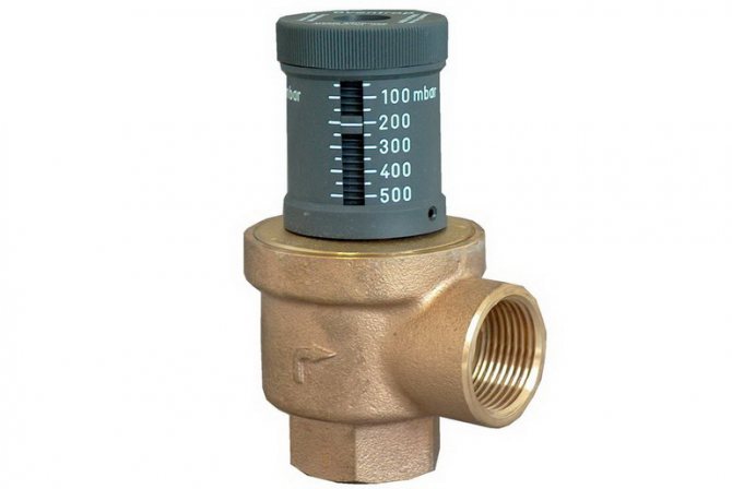
The bypass valve normalizes the pressure in the pipeline. The control valves redirect the energy carrier to an additional line circuit (bypass). The pressure of gas or liquid is maintained at the same level after the automatic release of surplus working medium. The valve plug opens when the pressure rises above the required value and closes when the pressure drops.
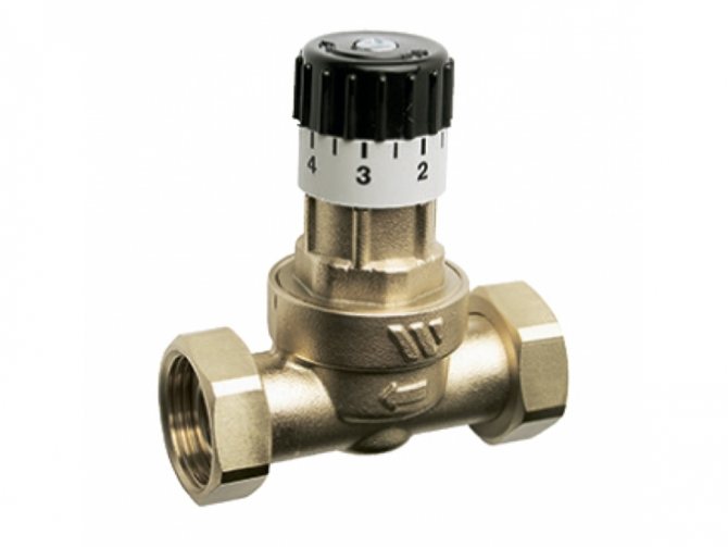
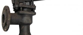
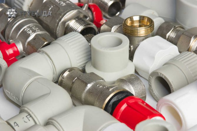
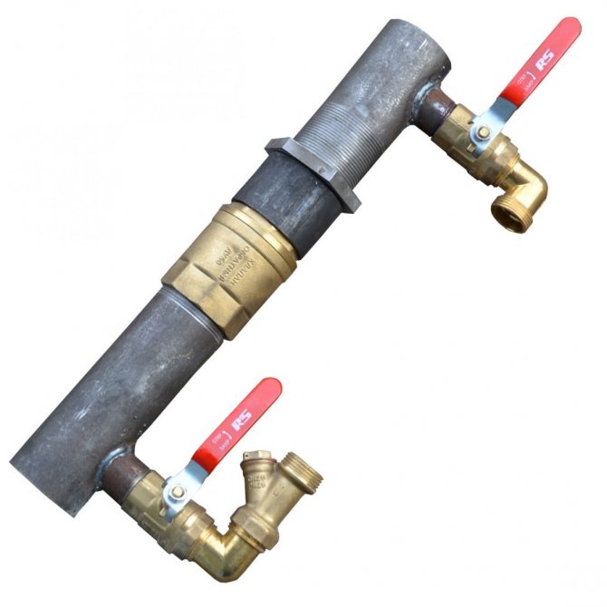
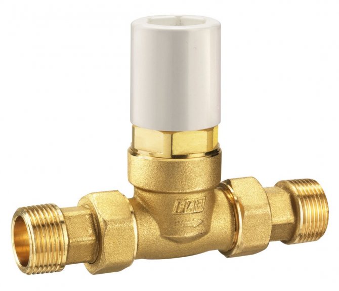
Overflow valve with fittings
What is it and what is it for
The volume of the coolant changes during operation. A change in pressure impairs the performance of the heating main. The pipes warm up unevenly, air accumulates in some areas, the nodes become unusable. The pressure balance is maintained manually, but it is better to entrust the change in the amount of fuel to the automation, which requires a valve in the system.
Device Specifications:
- DN is the nominal diameter of the connection nozzles. The value is used in the case of standardizing the typical sizes of manifold fittings. The actual DN may change slightly up or down. A similar characteristic was used in the post-Soviet period to designate the nominal diameter - Du.
- PN is the nominal size of the liquid or gas pressure at a temperature of + 20 ° C. The increase in pressure in the system remains within the standard limits, and the safety of operation is ensured. The characteristic was used in a similar designation Ru of automation in the post-Soviet period.
- Kvs is the coefficient of the ability to pass the volume of liquid when the heat carrier is heated to + 20 ° С. The decrease in pressure in the automation shows 1 bar. The coefficient is used in the calculations of hydraulic systems to identify pressure losses.
- The setting range is the difference in pressure change maintained by the automatic device. The indicator depends on the degree of spring elasticity.
Back
In gravity CO, there are conditions under which the coolant can change the direction of movement. This threatens to damage the heat exchanger of the heat generator due to overheating. The same can happen in sufficiently complex COs with forced movement of the coolant, when water, through the bypass pipe of the pumping unit, gets back into the boiler. Mechanism of action check valve in the heating system quite simple: it passes the coolant only in one direction, blocking it when moving back.
There are several types of this kind of fittings, which are classified according to the design of the locking device:
- disc-shaped;
- ball;
- petal;
- bivalve.
As it is already clear from the name, in the first type, a steel spring-loaded disk (plate), connected to the stem, acts as a locking device. In a ball valve, a plastic ball acts as a shutter. Moving "in the right" direction, the coolant pushes the ball through the channel in the body or under the cover of the device. As soon as the circulation of water stops or the direction of its movement changes, the ball, under the influence of gravity, takes its original position and blocks the movement of the coolant.
In the petal, the locking device is a spring-loaded cover, which is lowered when the direction of water in CO changes under the action of natural gravity. The bivalve element is installed (as a rule) on large diameter pipes. The principle of their work does not differ from the petal one. Structurally, in such an armature, instead of one petal, spring-loaded from above, two spring-loaded flaps are installed.
These devices are designed to regulate temperature, pressure, and stabilize the work of CO.
Areas of use
Automation regulates the pressure in the return and supply circuits of the pipeline, intended for closed-type heating mains. The pressure is normalized when the radiator valves are closed and the heat load is reduced.
The valve provides operational advantages:
- reduces the load on the running pump;
- prevents the formation of rust inside the boiler;
- eliminates noise and hum in pipes;
- increases the degree of heating of the energy carrier in the return loop;
- reduces hydraulic losses.
Overflow valves are used in pipelines of varying complexity. An automatic valve is installed to stabilize the pressure:
- In multi-circuit heat supply systems. Energy consumption decreases when one of the pipeline branches is disconnected, which leads to an increase in the head power. Maintaining the pressure at the required level avoids collector breakthroughs and overloading the heat generating unit.
- In heating pipelines where temperature regulators are installed, and in hot water mains. The amount of heating medium increases or decreases when the liquid temperature is adjusted. It is required to restore the balance of the pressure in the pipeline branch.
- In water supply lines with installed storage water heaters. Volume changes from frequent hot water intake lead to imbalances. The bypass device is used to prevent breakdowns and accidents.
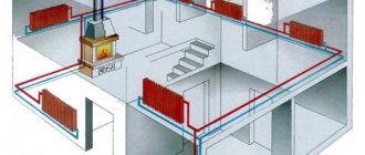
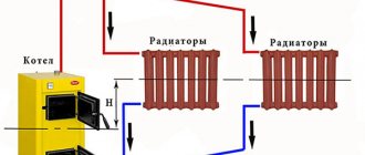
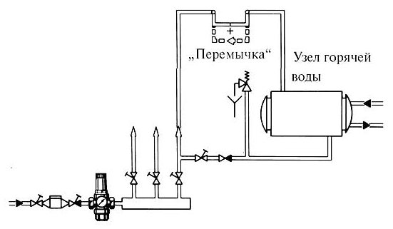
What is a heating bypass?
This is the name of a pipe section installed in such a way that an additional path is opened for the circulation of the coolant. A bypass in the heating system can direct water around a certain section of the main line or parallel to a pipe. The bypass section can be equipped with equipment, one end connected to the inlet pipe, the other to the outlet pipe.
The bypass valve is supplemented with shut-off valves to shut off the coolant supply through the bypass passage and regulate the flow of water to radiators and pipeline branches. For ease of disconnecting a part of the system, a battery or a certain area from the flow of the coolant, a ball valve is installed on the outlet pipe. Installation area - the area between the bypass valve and the outlet on the heating boiler, central riser or other device.
When a bypass device is used:
- in the process of piping radiators when arranging one-pipe circuits;
- when pumping equipment is installed in an autonomous heating system;
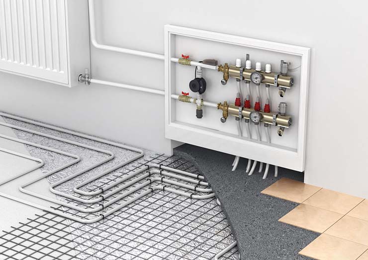
- at the point of installation of the mixing unit, when the contour of the underfloor heating is formed;
- in the process of arranging a small circuit for the movement of the coolant when tying a solid fuel boiler.
Principle of operation
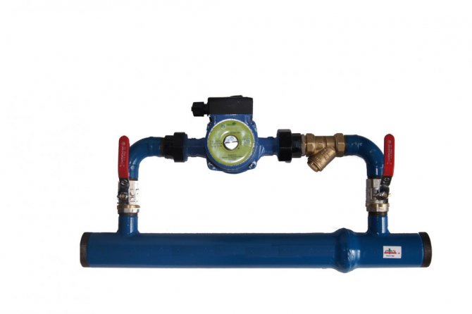
The automatic regulator is installed on an auxiliary line mounted after the pump or acceleration manifold. The bypass connects the drive circuit to the return collector. The liquid is also bypassed in the reverse flow if the heating boiler is part of the heating system, which is the principle of the bypass valve. Excess water is discharged to the external environment if the water heater operates in an autonomous line.
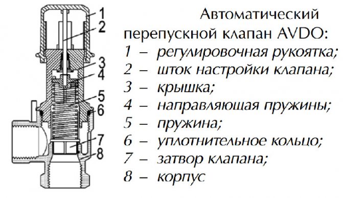
Bypass automation device:
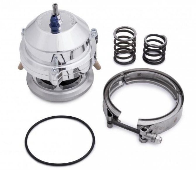
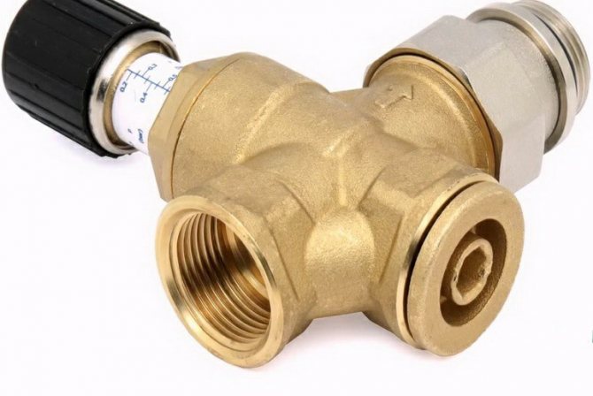
- the damper is located in a metal case, a spring is also installed there;
- the handle is located on the body, it is designed to adjust the permissible pressure;
- temperature sensors cut in additionally, a device for replenishing and venting the energy carrier is provided.
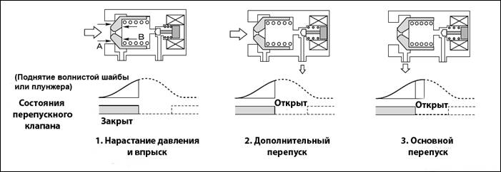
The damper applies pressure to the spring, releasing the passage in the body. The flow is redirected from the supply branch to the branch circuit. The pressure is leveled, the indicators are maintained in this state.The spring expands and moves the damper in the opposite direction when the pressure decreases. The liquid does not enter the bypass and the pressure is equalized under different operating conditions.
The straight-through valve is different from the pressure reducing device and safety automatics. The difference lies in the mechanism for reducing the pressure and the frequency of operation.
Types and designs
The device is available in the form of indirect and direct mechanics.
The straight automatic machine has a simple internal structure. The damper operates from the pressure of the coolant. The device is used because of ease of use, insensitivity to dirt and reliability. Automation is characterized by reduced accuracy when setting the nominal values.
The indirect action automation contains a pressure sensor and two valves:
- main, moving from a piston drive;
- pulse, having a small diameter.
When the pressure in the line decreases, the smaller valve puts pressure on the piston, which causes the main flap to move. The throughput of the automatic device is regulated by an indirect method. The valves are more precise, but unreliable due to the many operating elements.
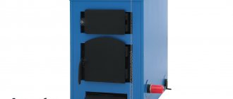
The systems use different heating devices. Each type requires a different overflow valve design:
- The direct valve is installed in electrical systems running on diesel or gas.
- Solid fuel units do not turn off quickly, smooth adjustment does not work. Valves are used that respond to changes in the temperature of the energy carrier and an increase in pressure. Automation is connected to the cold pipeline and external sewerage.
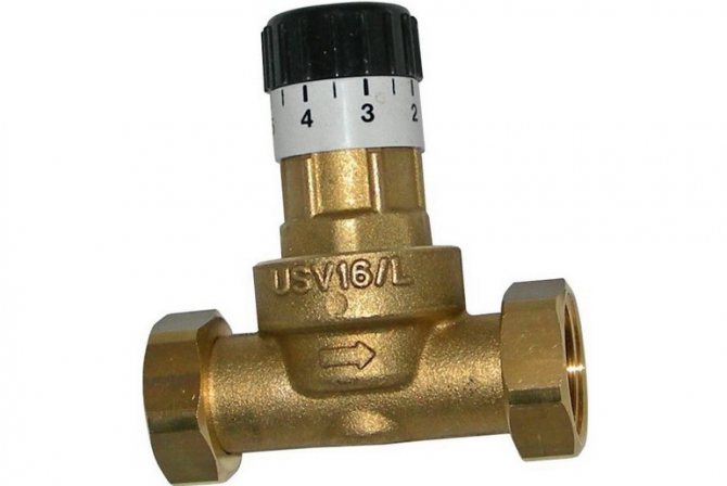
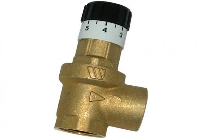
- The regulating handle is used in homes where the owner can independently set the allowable pressure.
- The auto valve is not used on open lines. The expansion vessel regulates the pressure in the network by compensation.
Selection Tips
The overflow valves correspond to the performance of heat generators, have the appropriate capacity and allowable pressure. The branch pipes are connected without fittings; for this, their diameter is selected so as not to increase the vulnerability of the pipeline.
Overflow valves are sometimes sold complete with a water heater or heating unit, or the device is purchased separately, depending on the type of fuel and technical characteristics. The ability of the user to set up automation and set operating parameters is taken into account. The price plays a role only when choosing a model of the same type of device with equal parameters, but differing in cost.
Selecting a specific type of monitoring device
If it is necessary to install a bypass valve for a pipeline system, its design must comply with GOST 24570-81, which describes the selection features. The main criteria are the features of the mechanism, the requirements for the pipeline, as well as the material from which the pressure reduction valve is made, while the adjustment mechanism must be reliably protected from the effects of the coolant.
There are situations when sticking occurs and the pressure relief valve does not work, for this, a stem must be provided in the design for manually retracting the spring.
Requirements to be met by a pressure reducing valve
In order for the device to be able to perform its functions optimally, it is necessary that its diameter is not less than the diameter of the inlet pipe. If this condition is not met, the hydraulic resistance will block the pressure reducing valve and it will be inoperative.
Another important point is frost protection, which the bypass valve should be equipped with, because at low temperatures its operation will be difficult.Special requirements are imposed on the materials from which the pressure reducing valve is made, and most often brass is used for this.
This metal has a minimum coefficient of expansion, which is very important due to the high temperature of the coolant.
In addition, it is distinguished by reliability and durability, which guarantees normal operation even at maximum pressure indicators, well, low cost is also very important.
Installing a pressure reducing valve
In order to be able to adjust the pressure value when the device is triggered, its design provides for the presence of a regulating block, which is made of plastic with high temperature resistance. The choice of material is due to the need to maintain rigidity even at very high temperature indicators of the coolant available in the system.
How is the pressure reducing valve installed?
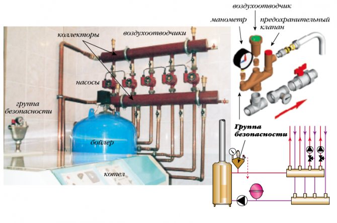
The installation of the bypass device has its own characteristics related to the location and operation of the expansion tank. The bypass valve should be triggered in cases where the expansion tank is not able to cope with its functions. Therefore, the pressure limiting valve must be located immediately behind the boiler outlet and there must be a distance between them between 20 cm and 30 cm.
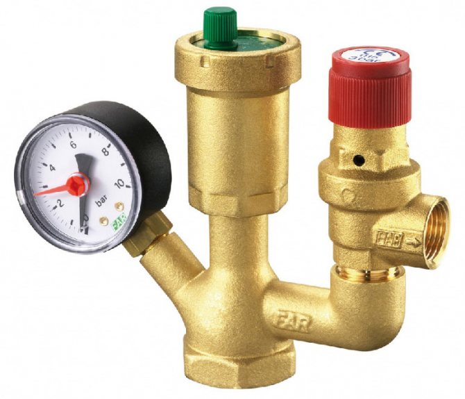
To obtain pressure indicators in the system and control, a pressure gauge is mounted in front of the valve.
As for the rules according to which the bypass valve is installed, they provide:
- Prohibition of the installation of shut-off equipment, valves and taps in front of the valve and the boiler.
- The presence of a drain tube installed on the outlet pipe, which is necessary in order to remove excess water from the system. Next, the tube is connected to the sewer, or return pipe.
- The bypass valve should be installed at the highest possible point in the system.
When to install a pressure reducer (video)
Maintenance of pressure reducing devices
During the operation of the heating system, it is necessary to regularly check the pressure limiting valve, especially if it has a spring structure. Sticking can occur, at which the value of the maximum pressure for its operation increases, which causes accidents and destruction of the pipeline.
The replacement of the limiting device should be carried out in cases where the number of emergency starts reaches 7 times, at least such recommendations are given by specialists.
It is very important that the pressure reducing valve is suitable for the performance and ensures the safe operation of the heating system.
Installation
The valve is installed according to the inset guide. Tips for the correct installation of different types of automation:
- a strainer is installed in front of the overflow valve;
- manometers are mounted before and after the valve;
- the device is cut so that its body does not experience mechanical torsion, compression or tension loads associated with the operation of the connected circuit;
- it is better to choose and install automation with the organization of straight sections in front of the valve (5DN) and after it (10DN);
- the overflow device is mounted on pipes located horizontally, obliquely or vertically, if there are no other instructions on this in the instructions.
Automation is set up after starting water into the line during the adjustment of the entire unit. It is allowed to adjust the valve in an empty pipeline if there is a permissible value.
The auto valve is regulated by creating the required difference at the location of the device, the screw is rotated until the valve opens. The difference is reduced and the closing moment of the damper is monitored, and the device is additionally adjusted.The pressure changes smoothly due to the fact that each turn of the screw corresponds to a clear range of pressure change.
Valve operation is verified by varying the differential pressure at the installation site. The accuracy of regulation and the opening speed of the damper are checked. The error is allowed within 10% at the boundary values. The set pressure corresponds to the opening moment, full expansion is achieved at values of a higher differential head.
Maintenance is done once a month, the setting pressure is checked, the speed at which the damper starts to open. The function of the bypass valve is checked by changing the pressure at its location. The filter is cleaned depending on the degree of contamination, as evidenced by the readings of the manometers.
Bypass valve
Controlling the flow of working media is the main and main task of control valves. The bypass valve in this context is responsible for maintaining the required pressure to its place of installation by automatically dumping excess pressure from the main line to the drain or bypass.
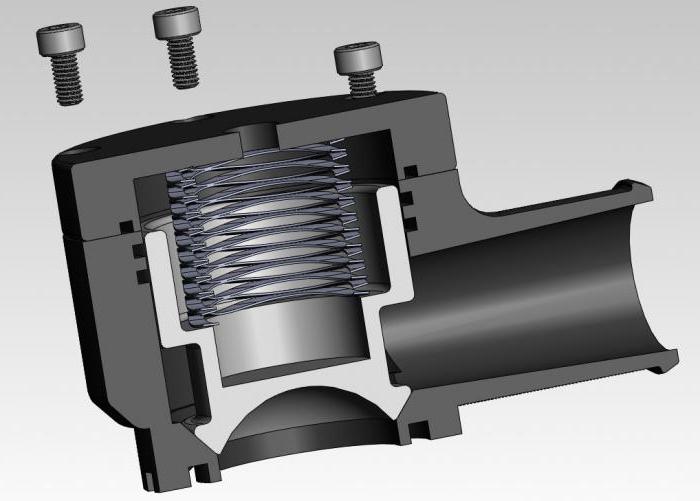
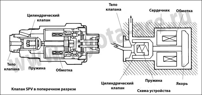
By design, the bypass valve is a direct-acting control valve. The control signal is received from the working medium itself and is transmitted through the diaphragm and the valve stem to the plunger to control the opening level. In the figure, the red zone is the setting pressure zone. With an increase in pressure, the medium presses on the membrane, and the discharge to the blue zone of reduced pressure comes off. When the set pressure is reached, the valve closes again. It should be borne in mind that since this is a control valve, and not a shut-off valve, in most cases there is a certain leakage in the valve seat, which depends on the type of seal and the quality of the valve itself.
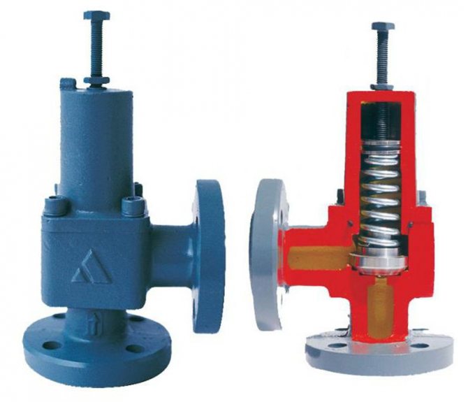
The bypass valve consists of the following main elements:
- Body and internal elements. The bypass valve, during its operation, in some cases experiences loads, perhaps even greater than the pressure reducing valve. This is due to the fact that large differences occur at the bypass valves at fairly low flow rates.
o requires the execution of internal elements with different spraying like stellite. Soft seals on the valve disc or seat are used only for fluids with low temperatures and relatively small pressure drops - otherwise they may undergo erosion. In addition, the operating pair seat / valve with the same diameter can have different cross-sections, which means that the valves can have different Kvs parameters. For example, a Mankenberg DM505 valve with the same diameter can be produced in 5 different Kvs options.
- Actuating mechanism. The overflow valve can be designed with either a diaphragm or a spring or piston actuator, depending on the differential, setting pressure and operating mode. Diaphragm is the most common, for example - GRANREG CAT 82, but at the same time it has limitations on pressure drops and setting pressure. At the same time, the diaphragm valve has the highest setting accuracy, like the Mankenberg UV3.0, where the accuracy reaches 0.001 bar. The piston is distinguished by the ability to work at high setting pressures, for example, Mankenberg UV8.2. Overflow valves with diaphragm or piston actuator require an impulse tube. Spring actuators have a very compact design, low cost and easy setup, but the capacity of valves with such an actuator is slightly lower. A prime example is the Goetze 630.
The overflow valve is selected based on the following basic parameters:
- Working environment. It is very important to understand that a bypass valve is a complex structure made up of many parts. Various elastomer seals are used to ensure the tightness of the valve and its function.Incorrect selection leads to valve failure with various consequences for the technology, as well as for the environment and for humans.
- Physical parameters of the working environment. Based on its viscosity, fluidity, the presence of abrasives and the state of aggregation, a bypass valve is selected with a specific design of the seat, valve plug and effective diaphragm area, and the operating temperature of the medium affects the materials of the valve and seals.
- Working parameters of the working environment. The main parameter by which the bypass valve is selected is its throughput. Only knowing the pressure to be maintained, the pressure of the medium downstream of the valve in the relief line, as well as the flow rate, can the valve be correctly selected.
- Additional terms. It is necessary to take into account not only the specified parameters, but also the ratio of inlet and outlet pressure, installation location, speed of working media in the system. The wrong choice leads to cavitation, inability to regulate and further destruction of the valve. In addition, do not forget about the valve installation location - this also affects the valve.
After a preliminary calculation of the throughput, materials of seals and the body, you can choose a bypass valve according to the manufacturer - who can offer the valve for the design parameters, as well as taking into account the installation site and other significant conditions.
In addition, do not forget that, like any control valve, the bypass valve must be supplemented with the following equipment:
- Shut-off valves, and on critical systems also a bypass line
- Filter to protect the internal elements of the valve
- Safety valve in the event of a sudden increase in pressure - to protect the valve and the system as a whole
- Pressure gauges for determining valve operation and setting
- When using with steam, the setting of the steam separator is strongly recommended, and a condensate tank is mandatory installed on the impulse tube.
Source: a-tepla.ru