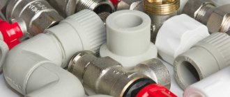
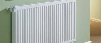
Why do you need a safety valve
When pumped into pipes, the heat carrier has a temperature of about +15 ºС, when heated in the boiler, the water begins to heat up, expand, increasing the in-pipe pressure. This can cause leaking welds, fracture or rupture of polymer fasteners. This can cause the boiler to explode. In the best case, there will be a short circuit of the boiler room electrical appliances.
If the degree of heat transfer of gas or liquid-fuel devices can still be controlled, then for solid-fuel devices this is impossible.
In the system on liquid energy carriers, the equipment is installed with sensors, built-in safety automation, which is triggered in an emergency and turns off the devices.
When heating with wood, coal, you can try to regulate the combustion force by closing the damper, but this takes time. The heat generator is inert, due to which the coolant overheats greatly.
When the oven is still in the warming up stage, it is enough to block the air supply to quickly extinguish the flame. If the combustion has heated up the boiler to the maximum permissible temperature, then the combustion will slow down, and the furnace will generate a lot of heat for some time.
A safety relief valve must be used to avoid the consequences of sudden or excessive pressure build-up. At the moment of overloading the system, the shutter closes, removing part of the excess steam to the outside. As soon as the volume of the load returns to normal, the shutter closes, goes off in anticipation of the next reset.
Bypass valve functions
During the heating of the coolant, it expands - a natural increase in volume leads to an increase in pressure on the inner walls of pipelines and heating devices. Exceeding a certain value (usually about 3.5 bar) breaks the tightness of the joints, which leads to gusts and emergencies. For the timely discharge of excess hot water, it is necessary to install a safety valve for the heating boiler, or, as it is also called, a bypass valve.
It should perform the following functions:
- Remove excess coolant in a timely manner, while reducing the pressure inside the system;
- Have the ability to customize. In an autonomous system of a private house, the safety valve for heating must have the function of manually setting the maximum allowable pressure value;
- Operational reliability. The construction and material of manufacture must ensure the normal operation of the safety valve for the heating system.
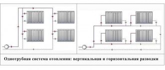
The choice of a particular model is influenced by the characteristics of heat supply - the value of the optimal and maximum pressure in the pipes, the location of the expansion tank, the length of the line and its type (one-pipe, two-pipe or collector). But before purchasing a device, you need to study the parameters that characterize the safety valve for heating: the principle of operation, design and installation specifics.
Types of valves and how they work
Any modification of the safety valves in the heating system includes a shut-off element and a force action mechanism. According to the design features, several types of fuses are distinguished.
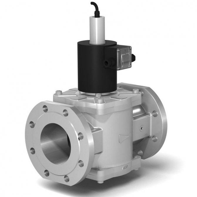
Separately classified are valves for dumping the thermal potential with a bellows, a temperature-sensitive liquid that compensates for load drops. There are models that include a safety group in the form of a blast valve with a part responsible for air discharge and a pressure gauge.
The check relief valve for the heating design can be spring-loaded or gravitational. Due to the built-in mechanisms, the contactor is kept closed, which ensures the movement of the coolant flow in one direction.
Closures are double-leaf, petal, disc, pressing against the saddle, bushing, other main base. It is necessary to get a sealed shutter.
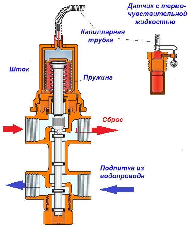
Inside view
The principle of operation of the fuse lies in the fact that in the normal state, the diaphragm layer fixed between the stem and the spring tightly adheres to the seat, hermetically closing the outlet. In the case when the coolant boils, expansion of the liquid is observed, the load inside the system rises, but is partially regulated by the expander.
At the maximum allowable load level, the spring is strongly compressed, releasing the diaphragm, which immediately opens the passage.
The lid rises to release as much hot steam as is required to stabilize the equipment.
When the work is normalized, the spring returns to its original position, the membrane tightly closes the release hole, the cap returns to its place.
If the owner is near the instruments, you can perform an emergency reset with your own hands by turning the upper handle.
By pressing method
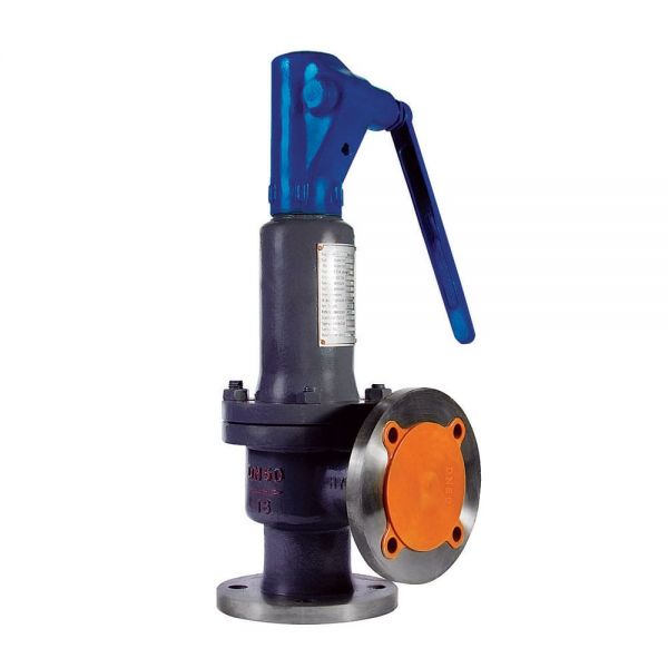
When heating a private house, apartment or industrial premises where low-power equipment is used, a spring-loaded valve for emergency relief of excess water pressure for the heating system is often chosen.
They are simple, compact, inexpensive but reliable models that can be combined with other equipment for safety.
The compression ratio of the spring is related to the load parameter at which the valve is actuated. The spring elasticity affects the setting range.
The principle of operation of the device: a water stream exerts pressure on the shutter, as it intensifies, the compression ratio of the spring increases. From this, the spool rod rises up, releasing excess steam, and the in-line fluid volume is stabilized. In the meantime, the spring returns the unit to its original state.
Spring modifications are made of high-strength brass, hot stamping technologies are used. The spring itself is steel, and the membrane, seals, and the handle are polymer.
You can choose models with factory settings or those that need to be customized individually during installation.
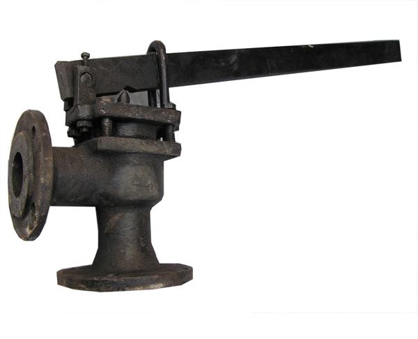
Lever fuse
Lever-weight safety devices are used less often, since the stem lifting provides an external suspended weight that moves along the entire lever, regulating the degree of pressure of the stem against the seat.
By the degree of opening the shutter
Low-lift valves assume a valve lift of no more than 0.05 times the seat diameter: the opening mechanism is fully proportional.
The product is characterized by low throughput and primitive design. The fuse is installed in installations with a liquid medium.
Full lift modification
The full lift variation contributes to the maximum allowable lift of the gate, which improves throughput as a large amount of steam is discharged at a time.
By response speed
The proportional safety valve for urgent relief of excess water pressure in the heating system assumes that the valve rises gradually, according to the degree of internal load. As the damper rises, the volume of the released steam increases smoothly. Such installations can be used with any type of boiler, but most often they are installed in systems with water or other liquid.
The on / off valves operate instantly, opening fully when the pressure rises. It is recommended to place such devices in a compressible environment.The main disadvantage of the safety element is the presence of self-oscillations of the bolt.
On-off valve
Installation of on-off valves should be carried out taking into account the discharge of a large amount of water with a sudden opening. It turns out a very quick release of pressure, closing the shutter, as a result - a water hammer, which is absent in proportional fuses.
You can learn more about the valve device, the principle of its operation, in the following video:
Operation and regulation of safety valves
In addition to maintaining the valve clearances specified by the manufacturer, care must be taken to ensure that all working parts are aligned and easily movable. Stem deformation is a common cause of valve sticking during operation.
When inspecting and disassembling safety valves, all parts and parts are marked in order to put them in place. Keep condensate drain openings clean to prevent water hammer.
Before adjusting the safety valves of any boiler, make sure that the boiler pressure gauge is accurate. It is advisable to have two parallel operating pressure gauges during regulation.
Safety valves must be adjusted to explode: on boilers with a working steam pressure of less than 1 MPa per 1.05 P of operating steam, and on boilers with an operating steam pressure of more than 1 MPa per 1.03 P of operating steam. The maximum steam pressure when the safety valve operates should not exceed more than 10% of the working steam pressure.
After detonation, the safety valves of auxiliary boilers for critical purposes must completely stop the output of steam when the pressure in the boiler drops at least 0.85 of the operating pressure.
At present, according to the rules of the classification societies, the safety valves of the forced circulation boilers must have separate outlet pipes. In addition, for waste heat recovery boilers that can operate with forced circulation, it is recommended to use direct-acting safety valves, which do not require precise maintenance of clearances for reliable operation.
Superheater safety valves are usually controlled to a lower pressure than steam manifold valves so that cooling steam is constantly flowing through the superheater. Otherwise, the steam movement in the superheater may stop due to lifting of the boiler steam drum valves when the superheater safety valves are closed.
Regulation of safety valves of a double-circuit boiler.
The safety valves are regulated in the same way as the valves of conventional water tube boilers.
The regulation of the primary circuit safety valves has its own characteristics. In the absence of the boiler manufacturer's instructions for maintaining the steam pressure required to regulate the primary circuit safety valves, the following should be done:
- to reduce the water level in the collector of the second circuit to the lower edge of the vapor-generating elements so that the vapor-generating elements cannot transfer heat to the water of the second circuit;
- set the normal water level in the steam drum of the primary circuit;
- to raise the steam pressure (from the cold state) to the maximum operating within 2 hours, and in the initial period until the pressure of 1.5 MPa is reached, the combustion intensity should be minimal;
- stop burning immediately when lifting the safety valves. Adjust the valves by periodically switching on the boiler nozzles, avoiding excessive losses of distillate;
- adjust the boiler protection system for steam pressure (it must stop the fuel supply at a steam pressure that is 0.1 MPa lower than the pressure to which the safety valves are adjusted);
- Under no circumstances should the hot collector of the secondary circuit be supplied with cold water, which may cause cracks.
To ensure the operation of economizers or boilers with forced circulation, in non-steam mode, it is customary to regulate their safety valves to a pressure slightly higher than the valves of the boiler or steam collector to which they are connected.
Similar articles
- Marine auxiliary boiler fittings
- Combined heat recovery boilers
- Marine recovery boilers, purpose, device
- Shukhov system vertical combined boiler
- Auxiliary double-circuit boiler
- Auxiliary water tube boilers
- Auxiliary fire tube boilers
- Classification of marine auxiliary boilers
- The main indicators characterizing the boiler
- The purpose of the auxiliary boiler plant and its diagram
Rating 0.00 (0 Votes)
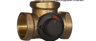
Features of Three Way Emergency Valves
Three-way safety valves for heating construction are used in heating systems at low temperatures in the circuit.
The design provides for the presence of three holes, where one is inlet, and the other two are outgoing. Internal flows are controlled by a ball or stem valve, and fluid distribution is performed by rotations.
The valve is responsible for ensuring that all areas of the circuit are delimited, the flow density is evenly distributed over all zones, the temperature is normalized.
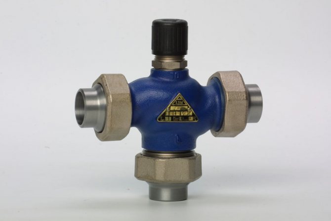
Three-way valve
If there is a floor heating system, too hot a flow should not be allowed along the floor circuit; it will need to be mixed with the cooled liquid, which provides a three-way model.
The work takes place under the control of a temperature sensor, which is placed in a low-temperature circuit. Then, in the event of deviations, a shutter mechanism is triggered, admitting or restricting the exit of liquid from the return pipes.
Appendix A. Calculation of the valve capacity
(mandatory) Calculation of the valve's capacity
In this annex, the following symbols are adopted: G - throughput of the valve, kg / h; IN 1 - coefficient taking into account the physicochemical properties of water vapor at operating parameters in front of the valve; IN 2 - coefficient taking into account the pressure ratio in front of the valve and behind the valve; IN 3 - coefficient taking into account the physical and chemical properties of gases and vapors at operating parameters; AT 4 - coefficient of compressibility of real gas; F - valve sectional area equal to the smallest sectional area in the flow path of the seat, mm2; α1 - the flow coefficient corresponding to the area F for gaseous media; α2 Is the flow coefficient corresponding to the area F for liquid media; Р1 - the greatest overpressure in front of the valve (overpressure before the valve, equal to the full opening pressure), MPa (kgf / cm2); P2 - the highest overpressure downstream of the valve (overpressure downstream of the valve in its fully open position), MPa (kgf / cm2); ρ - density of vapor, gas or liquid in front of the valve at parameters P1 and T1, kg / m3; R - gas constant; T1 - temperature of the working medium in front of the valve at a pressure of P1, K; k Is the adiabatic exponent; V1 - specific volume of steam in front of the valve at parameters P1 and T1, m3 / kg; β - pressure ratio; βcr - critical pressure ratio. A.2 The throughput of the safety valve should be calculated using the formulas: for water vapor:
- for pressure in MPa, - for pressure in kgf / cm2;
for other vapors and gases:
- for pressure in MPa, - for pressure in kgf / cm2;
for liquids:
- for pressure in MPa,
- for pressure in kgf / cm2;
where ρ is determined by tables or state diagrams; the density of the real gas is also calculated by the formulas:
- for pressure in MPa; - for pressure in kgf / cm2;
R - determined according to Table A.1; B4 - determined according to table A.2 (for ideal gas B4 = 1); B1 - determined according to table A.3 for saturated water vapor and according to table A.4 for superheated water vapor or calculated by the formulas:
- for pressure in MPa;
- for pressure in kgf / cm2;
B2 - determined according to Table A.5 depending on k and β; B2 = 1 at β ≤ βcr, where - for pressure in MPa,
- for pressure in kgf / cm2,
βcr - determined according to Table A.1 or calculated by the formula:
;
B3 - selected according to tables A.1 and A.6 or calculated by the formulas: for pressure in MPa:
- at β ≤ βcr;
- at β ≥ βcr;
for pressure in kgf / cm2;
How the valve works in conjunction with an expansion tank
The expansion device performs regular checks, but does not protect against breakdown in emergency situations. Sometimes the tank cannot work properly because there is no air inside.
The tank is not capable of replacing the blast valve to protect the boiler or vice versa. Each of the elements has its own threshold of impact on the system, so one of them cannot be used instead of the other.
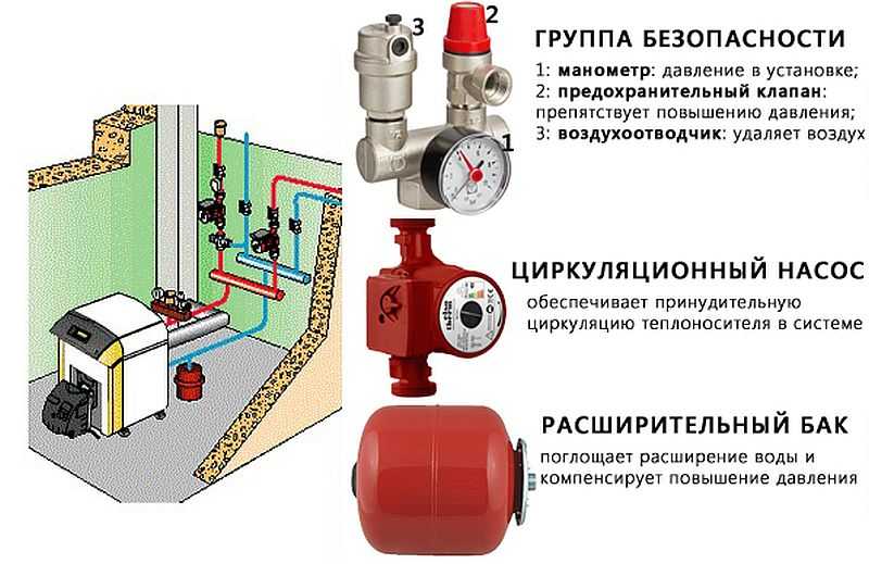
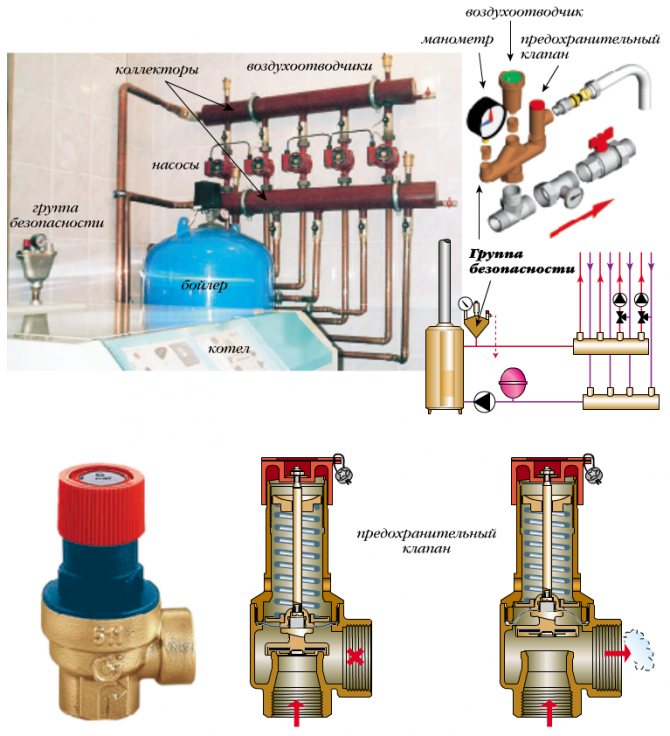
Example of equipment for a safety node
The expansion unit can temporarily accept small amounts of excess, but with a large intake of excess steam through several discharges, the tightness of the device is broken, and a constant leak appears.
The safety part is only needed for emergencies when the system is under extreme stress. After the pressure has returned to normal, it is necessary to take measures to eliminate the causes of such a jump.
Both devices protect the pipes and the boiler room in case of sudden pressure drops.
Requirements for Direct Acting Relief Valves
5.1. Lever-weight valves may only be installed on stationary vessels. 5.2. The design of the cargo and spring valve should provide for a device for checking the correct operation of the valve in working condition by forcibly opening it during the operation of the vessel. Forced opening must be ensured at a pressure equal to 80% of the set pressure. It is allowed to install valves without devices for forced opening, if it is unacceptable due to the properties of the working environment (harmful, explosive, etc.) or according to the conditions of the work process. In this case, the valves should be checked periodically within the time limits established by the technological regulations, but at least once every 6 months, provided that the possibility of freezing, sticking, polymerization or clogging of the valve by the working medium is excluded. 5.3. Valve springs must be protected from impermissible heating (cooling) and direct action of the working medium, if it has a harmful effect on the spring material. 5.4. The weight of the load and the length of the lever of the lever-weight valve should be selected so that the load is at the end of the lever. The ratio of the lever arms should not exceed 10: 1. When using a suspended load, its connection should be one-piece. The weight of the cargo must be no more than 60 kg and is indicated (embossed or cast) on the surface of the cargo. 5.5. It must be possible to remove condensate from the places of its accumulation in the valve body and in the outlet pipelines.
When the valve is triggered
Situations when an emergency release of pressure occurs:
- There is little coolant in the pipeline.
- Auto-fill failed.
- The absence of the expansion tank or its overlap. It also affects blood pressure a lot.
- Equipment breakdown, lack of air in its upper segment worsens the situation.
Valve functionality
When the boiler is operated at very high power, a lot of steam is produced, which is impossible to handle even with the most reliable expander.
When protection is needed
When installing equipment, it is best to immediately install an independent valve.
It is necessary to install a device on the hot water supply system if the water is heated not by the flow method, but from the heating boiler.
Separate closed circuits heated by a heat exchanger or other heat source are also fused.
The valve is needed in various hydraulic connections operating under pressure or with a compressor pump.
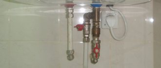
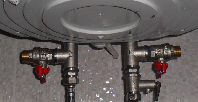
Installation of the valve in the heating system
The safety valve is placed immediately behind the boiler outlet (it is enough to retreat 20-30 cm). A pressure gauge is required for visual control, monitoring the state of the system.
Do not place shut-off valves, gate valves or shut-off devices between the valve and the main heat source.
Where is the valve
To remove excess water through the outlet, install a special drain pipe connected to the sewer or return line of the pipeline.
If a closed-type gravitational system is installed, then the fuse is set at the highest point.
Selection recommendations
Quality emergency relief valves are rarely cheap as they are made from bronze, brass or stainless steel. The main thing is to look for a normal price-quality ratio.
The selection of the simplest option is allowed, which costs little, but it is problematic to check it regularly.
Increases costs, but improves safety performance gauge to help monitor equipment health.
A bellows valve will help to make a small heating system autonomous.
It is important that the main mechanism is reliable enough, but not very elastic, and the adjustment is comfortable. It is necessary to immediately check the correspondence of the diameter of the fuse and the pipe emanating from the boiler, so that you do not have to change the part.
If the pipes are of small diameter, then ball or poppet equipment will be sufficient. The gravity valve is mounted only in a horizontal position, and the main shutter is always made of a petal type.
It is necessary to install several air vents if a boiler or riser is used. With a water type of heating, an expander is placed at the highest point, which replaces several air vents. But this option complicates maintenance and takes up a lot of space.
Control fittings are selected based on what degree of comfort is expected, what is the expected life of the heating. When set to the minimum setting, the noise level is reduced and in a water-heated situation, rust is prevented. The armature elements reduce the load, increase the resource values of the circulation pump.
When the coolant is oil, or the heating works well, a bypass valve is installed that works constantly, reliably providing the required level of protection.
The safety relief valve for the boiler is equipped with a special numerical marking with the letters atm, which indicates how much pressure a particular product can withstand in order to work properly.
The usual set pressure for a household fuse is 3 atm. The preload is only 1.5 atm, and the working pressure at maximum temperatures reaches 2.5 atm. This means that when the indicated parameters are exceeded, the situation becomes emergency, and the valve must be triggered.
For quality products, the minimum strength indicator is 4 atm, it is sometimes exceeded when manually pouring heating fluid.
The safety control valve stabilizes the entire system at a safe level.
The reduction model normalizes the force of the coolant inflow by adjusting the internal section of the inlet part of the pipeline.
The lever-weight variation assumes application for large pipelines with a large cross-section, includes a spool that opens the shut-off valve. The mechanism is triggered when the pressure level exceeds the weight of the weights attached to the handle.
In closed systems, a pressure valve is sometimes installed, the degree of operation of which is manually adjusted. With the help of an adjustable thermal head and mechanical action on it, it is very convenient to adjust the operation through the servo drive.
The bypass product reduces the load from the coolant, stabilizes the heating functionality. It is installed instead of a relief valve: temperature is injected in the return pipeline, after which the excess part of the liquid returns back to the common line. The pressure is now regulated.
The part is located behind the circulation pump, connected simultaneously to the supply and return pipes.
Conclusions and useful video on the topic
How the safety valve works and what it consists of:
Emergency valve in the safety group:
For more information on selecting and installing the optimal safety valve:
A safety valve is a simple and reliable equipment that will allow you to protect your home from unforeseen emergencies that occur in heating systems. To do this, it is enough to choose a high-quality device with suitable parameters, and then perform its competent setup and installation.
Are you looking for a suitable safety valve for your heating system? Maybe you still have questions, the answers to which you did not find in the above material? Ask our experts by leaving a comment under the article.
Or maybe you want to supplement the material with interesting facts and useful recommendations? Or share your experience of manually installing the valve into the system? Write your opinion on the need for such a protective device, share advice on choosing, based on personal experience.
First, I propose to understand: what is a safety valve, what is it for and why should it be selected at all? Maybe you should take the most beautiful one and install it?
A safety valve (definition of GOST R 52720) is a pipeline valve that protects (in fact, that is why it is a safety valve) equipment if the pressure suddenly rises there (we do not need it, high pressure). He does this by opening at the right moment (in fact, that is why he is a valve) and releasing that "unnecessary" pressure, and then he will close at the right moment (closing pressure). How does this happen? There is no magic here. The valve contains a spring which, during normal operation, (working pressure before the valve) closes the passage with its power (the spool is pressed tightly against the seat), and nothing is dumped anywhere. But if suddenly the pressure begins to rise, the spring no longer has enough strength to hold it, and the valve opens (opening pressure), the pressure is released.