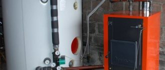
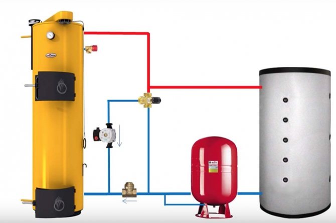
Solid fuel boiler plants cannot operate for a long time without the intervention of a person who must periodically load firewood into the furnace. If this is not done, the system will begin to cool down, and the temperature in the house will drop. In the event of a power outage when the furnace is completely burnt out, there is a danger of boiling up of the coolant in the jacket of the unit and its subsequent destruction. All these problems can be solved by installing a heat accumulator for heating boilers. It will also be able to perform the function of protecting cast iron installations from cracking at a sharp drop in the temperature of the supply water.
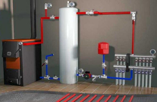
Tying a solid fuel boiler with a heat accumulator
The design and operation of the heat accumulator
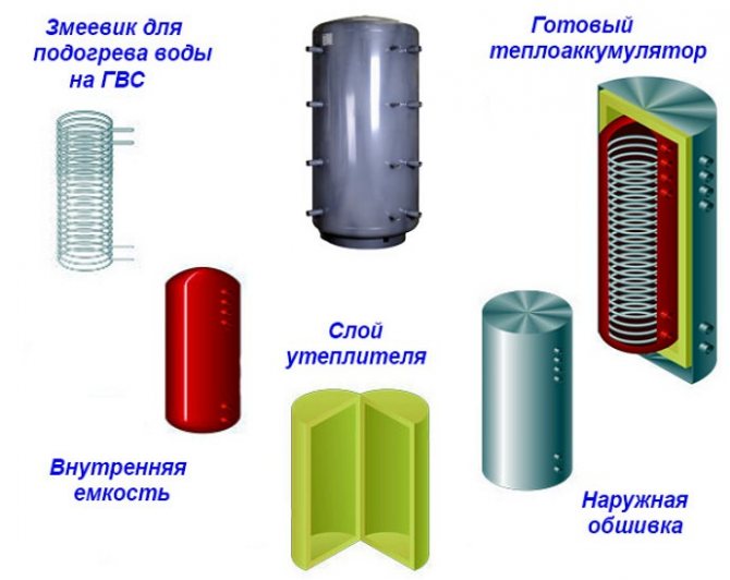
The device of a buffer tank for a heating system of a private house is not particularly complicated, but there are design features. A standard heat accumulator for boilers is an ordinary metal container with a calculated capacity, wrapped in a layer of thermal insulation.
In the simplest samples of factory production, there are only nozzles through which a solid fuel boiler is connected, and sleeves for mounting thermometers. In the buffer tanks of the higher price category, thermometers are already integrated, and the most expensive models are equipped with a coil-shaped heat exchanger.
The purpose of the coils in the design of the storage tank is to heat the liquid for supplying hot water and to connect solar panels. Naturally, this function is only needed under suitable weather conditions. In general, the heat accumulator for a solid fuel heating boiler is designed to solve the following tasks:
- Creation of conditions for the operation of the heat generator with maximum efficiency and minimum emissions into the atmosphere.
- Comfortable use of the TT-boiler, when there is no need to throw firewood into the furnace every few hours, including at night.
- Heating and supply of drinking-quality liquid to 1-2 points of water intake (optional).
Most manufacturers of solid fuel heating equipment indicate in the documents that it is highly recommended to connect the heat accumulator to the TT boiler.
The reason is this: the heat generator achieves the highest performance when the operating mode is close to the maximum. The surplus of produced thermal energy must be attached somewhere before it is fed into the heating system, and for this, a buffer tank with water is required.
Without the presence of a thermal accumulator, we are trying in all possible ways to "strangle" the boiler, limiting the supply of oxygen for the combustion process. Such actions not only reduce the efficiency of the heating unit to 40%, but also provoke the release of toxic carbon monoxide into the ambient air.
Why you don't need to visit the boiler room so often: the thermal energy reserved in the buffer tank will be used for heating the building for a long time, provided that its volume is correctly calculated. In addition, with the combined operation of a TT-boiler with a heat accumulator, the threat of overheating and boiling of the liquid in the jacket of the device is reduced to almost zero.
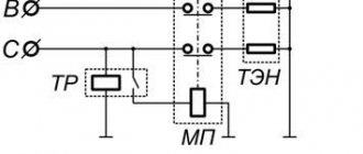
In addition to working with wood-burning heat generators, heat accumulators can also be used with units powered by electricity. However, such a symbiosis is rational only under the condition that at night the rate of consumed electricity is 2-3 times lower than the daily rate.During the night, the electrical installation is able to fully "charge" the heat storage, and it will transmit this energy to heat the building during the day.
Attention! With this option for using an electric boiler, the calculation of the power of the device must be doubled so that its heat transfer is sufficient to heat the building and load the tank at the night rate.
Since the device of the heat accumulator is not a secret, many craftsmen make a storage tank with their own hands. Plumber Portal will also tell you about the technology of self-assembly.
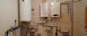
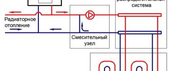
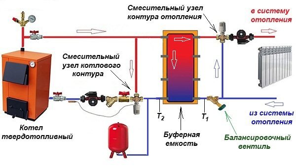
Hydraulic separation scheme
Another, more complex connection scheme, implies an uninterrupted supply of electricity. If this is not possible, then it is necessary to provide for connection to the network through an uninterruptible power supply. Another option is to use diesel or gasoline power plants. In the previous case, the connection of the heat accumulator to the solid fuel boiler was independent, that is, the system could work separately from the tank. In this scheme, the accumulator acts as a buffer tank (hydraulic separator). A special mixing unit (LADDOMAT) is built into the primary circuit through which water circulates when the boiler is fired up.
Block elements:
- circulation pump;
- three-way thermostatic valve;
- check valve;
- sump;
- Ball Valves;
- temperature control devices.
Differences from the previous scheme - all devices are collected in one block, and the coolant goes to the tank, and not to the heating system. The principle of operation of the stirring unit remains unchanged. Such a piping of a solid fuel boiler with a heat accumulator allows you to connect as many heating branches as you like at the outlet from the tank. For example, to power radiators and floor or air heating systems. Moreover, each branch has its own circulation pump. All circuits are hydraulically separated, excess heat from the source is accumulated in the tank and used when needed.
Advantages and disadvantages
A heat accumulator for a heating system, in which a solid fuel unit is used as an energy source, has a lot of advantages:
- Improving the convenience of operating the boiler, since after the completion of the burning of wood, the heating system continues to supply the dwelling with warm water from the tank. There is no need to get up in the middle of the night to load a new portion of fuel into the combustion chamber.
- The presence of the accumulator protects against boiling and breakage of the water jacket of the heat generator. If the electricity is suddenly cut off or the thermostatic heads installed on the batteries cut off the circulation of the coolant due to the achievement of the required temperature, then the boiler will heat the liquid in the tank.
- The supply of cold water flow from the return pipeline to the hot cast-iron heat exchanger is excluded after an unexpected start of the circulation pump, that is, it protects the cast-iron core from a sharp temperature drop.
- Heat accumulators can be operated as a hydraulic arrow, which makes the functioning of all circuits of the system independent, and this also leads to heat savings.
The need to comply with all the requirements for the location of the buffer tank and the increase in the cost of organizing the heating system are the only negative features of the use of storage tanks. However, this investment and installation inconvenience will be followed by minimal costs over the long term.
Selection recommendations
The selection of a heat accumulator for a solid fuel boiler is influenced by the presence of free space in the room. When buying a large storage tank, it will be necessary to provide for a foundation device, since equipment with a significant mass cannot be placed on ordinary floors.If, according to the calculation, a tank with a volume of 1 m3 is required, and there is not enough space for its installation, then you can purchase 2 products of 0.5 m3 each, placing them in different places.
Another point is the presence of a DHW system in the house. In the event that the boiler does not have its own water heating circuit, it is possible to purchase a heat accumulator with such a circuit. Of no small importance is the value of the working pressure in the heating system, which traditionally should not exceed 3 bar in residential buildings. In some cases, the pressure reaches 4 bar, if a powerful home-made unit is used as a heat source. Then the heat accumulator for the heating system will have to choose a special version - with a torispherical cover.
Some factory hot water accumulators are equipped with an electric heating element installed in the upper part of the tank. This technical solution will not allow the coolant to cool down completely after stopping the boiler, the upper zone of the tank will be heated. Domestic hot water supply will operate.
Varieties of heat accumulators
All storage devices perform almost the same functions, however, they have certain design features. Manufacturers produce buffer tanks of three types:
- hollow (no internal heat exchanger);
- with 1-2 coils, which contribute to the more efficient functioning of the devices;
- with built-in boiler tanks for the correct functioning of the DHW system.
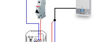
The heat accumulator is connected to the heating boiler and the communication wiring of the individual heating system using threaded holes located on the outer casing of the device.
Hollow storage. A tank without an internal coil and a boiler is considered the most primitive device and is priced cheaper than modified counterparts. This unit is connected to one or more boilers using central communications, and then wiring to the consumption points takes place with the help of branch pipes.
Connection to an additional electric heater is possible. A hollow device is able to provide high-quality heating of a private house, minimizes the likelihood of excessive water heating and ensures absolute safety of the system for the consumer.
Unit with one or two coils. Heat storage models with internal heat exchangers are more advanced options for a wide range of uses. The upper coil in the structure is responsible for collecting heat, while the lower heat exchanger performs the enhanced heating of the buffer tank itself.
The existence of heat exchange departments in the device makes it possible to receive hot water for domestic needs around the clock, to heat the container from solar panels, to warm up the buildings near the house and to use heat in the most rational way for any purpose.
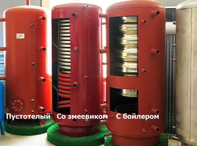
Product with an internal boiler. Such a heat storage device is a progressive device that not only accumulates excess heat produced by the boiler, but also ensures the supply of hot water to the points of water intake. The internal boiler tank is made of stainless alloy steel and is equipped with a magnesium anode. This device reduces the level of water hardness and prevents the formation of limescale on the walls.
The heat accumulator of this type is connected to various types of boilers and is capable of functioning with both open and closed systems. An accumulator with an internal boiler is also able to control the temperature level of the coolant and protects the heating circuits from overheating of the equipment.
The installation of such a device reduces fuel consumption and also reduces the number and frequency of downloads.It can be combined with solar panels of any model and can function as a hydraulic switch.
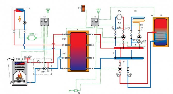
Heating circuit with a buffer tank-heat storage, and a solid fuel boiler
Consider another scheme for heating a private house with a solid fuel boiler, which is offered by one of the Russian manufacturers of buffer tanks - heat accumulators. A detailed description of the buffer tank design can be found here.
|
| Heating scheme of a private house with a solid fuel boiler and a buffer tank - a heat accumulator (to enlarge, click on the picture). The heating system is open, operates at atmospheric pressure, but with forced circulation of the coolant in the heating circuits. |
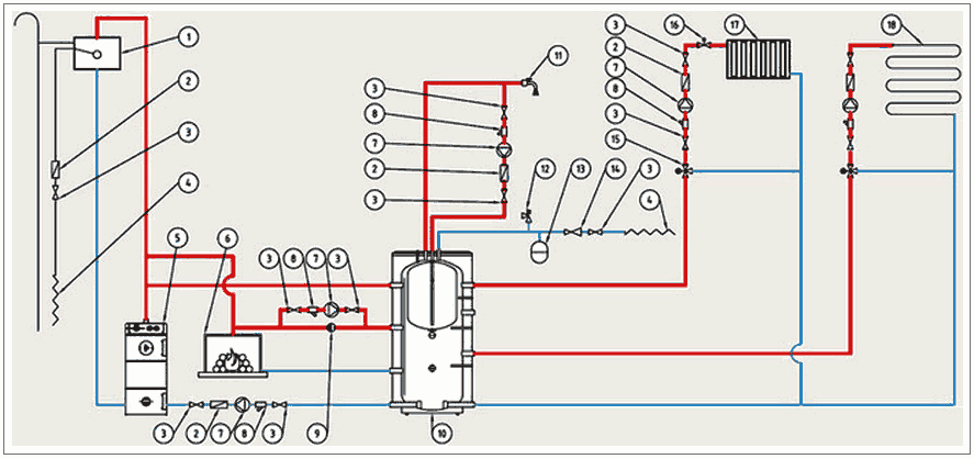
In the diagram: 1 - expansion tank with a float shut-off valve; 2 - check valve; 3 - shut-off valve; 4 - input of the water supply network; 5 - solid fuel boiler; 6 - fireplace with a water jacket; 7 - pump; 8 - filter; 9 - differential valve (vertical); 10 - buffer tank; 11 - analysis of hot water in the house ;; 12 - safety valve; 13 - membrane expansion tank; 14 - pressure reducer; 15 - 3-way mixing valve; 16 - thermostatic valve; 17 - heating radiators; 18 - floor heating pipes;
This scheme differs from the first one in that the heating system here is open and operates under atmospheric pressure. The hot water heating circuit is under pressure from the water supply network.
To charge the battery with heat, two sources are used - a solid fuel boiler and a fireplace with a water jacket.
The disadvantage of the scheme is that it does not provide a mode for protecting the boiler from low-temperature corrosion when the boiler is fired up. In the boiler firing mode at a coolant temperature of less than 55 degrees. Condensation from flue gases forms on the surface of the heat exchanger in the boiler. The condensate mixes with the combustion products and gradually clogs the heat exchanger, which reduces the boiler efficiency. In addition, deposits accelerate metal corrosion, which shortens the life of the boiler.
Accumulator for solid fuel and electric boiler
Buffer tank with TT boiler. The main characteristic feature of a solid fuel boiler is its cyclical nature. First, firewood is placed in the combustion chamber and heating is carried out for a certain period of time. The maximum power of the unit and the highest temperatures, that is, its maximum performance, are observed at the peak of the burning of the batch load.
After that, the heat transfer gradually decreases, and when the wood completely burns out, the production of useful heating energy is interrupted. All boilers operate according to this principle, including long-burning units.
It is impossible to fine-tune the device to generate heat at any given moment. This function is only available in modern electrical and gas installations. Therefore, immediately at the time of ignition and at the time of reaching the actual power, and then in the process of cooling and the forced passive state of the boiler, the thermal energy for full heating of the house and heating of hot water may simply not be enough.
But during the peak operation of the unit and the active phase of fuel combustion, the amount of energy released will be excessive and most of it will simply disappear. As a result, the resource will be spent inappropriately, and the owners will need to regularly load new portions of firewood into the furnace.
This problem is solved by the installation of a heat accumulator, which at the peak moment of combustion will take away excess heat and, at the right time, give off the thermal energy of the liquid. The coolant heats up and starts circulation through the mains and radiators, heating the building bypassing the cooled boiler.
Accumulator for the electrical system. Heating a house with electric energy is a rather expensive method, but sometimes it is equipped due to the inability to use other types of fuel. It is clear that with this heating option, electricity costs will increase significantly and maintaining comfortable conditions in the house will cost a lot of bills.
To reduce the cost of paying for electricity, you can use the equipment at the maximum during the preferential tariff period, however, for such a mode of operation of the device, a large-volume buffer tank is required. The capacious reservoir will store the heat energy produced during the grace period, then it can be spent on heating the home and supplying hot water to the water intake points.
How to calculate the buffer capacity?
The main criterion by which a heat accumulator is selected for a solid fuel boiler is its volume, the value of which depends on:
- heat load on the heating system;
- heating boiler power;
- expected duration of operation without a heat source.
Before calculating the capacity of the buffer tank, it is necessary to clarify all the aspects given, starting with the average heat input that the system consumes. It is not worth taking the maximum power for the calculation, this leads to an increase in the dimensions of the collector, and, consequently, to an increase in the price of the unit.
It is better to endure the inconvenience of frequent loading of the furnace for a couple of days a year than to spend a lot of money on buying a large heat accumulator, which will be used inefficiently.
Attention! To provide heat to a residential building with an area of 200 sq. m. enough buffer tank, containing 1 ton of coolant, and this is the volume of 1 sq. m.
In this case, the heating system with a heat accumulator will not work correctly if the boiler does not have enough power. In such a situation, it will never be possible to "charge" the drive in full, since the generator must immediately heat the dwelling and load the tank. Therefore, a solid fuel boiler for piping with a heat accumulator must have a double reserve of thermal power.
We propose to study the method of calculating the required volume of a heat accumulator using the example of a building with an area of 200 sq.m. when the heat generator is idle for 8 hours. Suppose that the water in the tank warms up to 90 ° C, and cools down to 40 ° C in the process. To warm up such an area in the coldest time, 20 kW of heat will be required, and its average consumption will be approximately 10 kW / h. Therefore, the tank must store 10 kWh x 8 h = 80 kW of energy.
Further, the calculation of the volume of the buffer tank for a solid fuel boiler is carried out according to the formula for the heat capacity of water:
m = Q / 1.163 x Δt, Where:
Q - the estimated amount of heat energy to be accumulated, W; m - mass of water in the tank, kg; Δt is the difference between the initial and final temperatures of the coolant in the tank, equal to 90 - 40 = 50 ° С; 1.163 W / kg ° С or 4.187 kJ / kg ° С - specific heat capacity of water.
For the example under consideration, the mass of water in the container will be:
m = 80000 / 1.163 x 50 = 1375 kg or 1.4 m³.
As a result of calculations using the formula, we found out that the volume of the buffer tank is slightly larger than the recommended one. The reason is simple: inaccurate initial data were taken for the calculation. In practice, especially when the housing is well insulated, the average heat consumption per area is 200 sq. M. will be less than 10 kWh.
For reference... There is also an enlarged method of calculation, according to which for each kW of the boiler's thermal power there is 25 liters of heat accumulator volume.
Hence the conclusion: in order to correctly calculate the volume of heat storage for a solid fuel boiler, it is necessary to apply more accurate initial data on heat consumption.
Calculation of the volume of the buffer tank
It is better to entrust the design of heating a private house from scratch to specialists. A professional approach allows you to avoid mistakes, which ultimately reduces the cost of heating the premises.If there is a need to modernize an existing heating system, the approximate dimensions of the heat accumulator can be calculated independently. To calculate, use the following formula:
V = Q / (K × C × Δt), where
- V is the volume of the coolant,
- Q - the amount of energy required for storage, W,
- K - boiler efficiency (indicated in the passport),
- С - 1.16 W / dm3 (specific thermal capacity of water),
- Δt is the temperature difference between the supply and return flow of the heat carrier.
To make it clearer how this happens in practice, we will give a small example. Let's try to calculate the dimensions of the buffer tank for accumulating power of 40 kW when connected to a heating system with a delta temperature of 30 ° C and a boiler efficiency of 70%. Substituting the initial data into the above formula, we get:
V = 40,000 / (0.7 × 1.16 × 30) = 1642 dm3
This means that for normal operation of the heating system, a heat accumulator with a volume of 1642 liters or 1.642 m3 should be installed.
Heat storage selection criteria
Other criteria for the selection of a buffer tank for heating are not so significant and, mainly, relate to a variety of additional options.
One of them is a built-in coil that heats the liquid for household needs. It can be very useful in the absence of other sources of heating, however, for a high flow rate in the DHW network, this option is definitely not suitable. In addition, the heat exchanger will take part of the "charge" of the heat accumulator, reducing the duration of the autonomous heating operation.
Another useful option is a heating element built into the upper part of the reservoir, which is able to maintain the temperature of the coolant at a set level. Thanks to the electric heating, the system will not defrost in the event of an accident and will even be able to heat the house for some time after the heat accumulator is “discharged” and the generator has not yet started to work.
Another coil for connecting solar collectors can be useful only in the southern regions, where the activity of the Sun will make it possible to charge the heat accumulator.
But what you really need to pay attention to when choosing a device is the working pressure of the storage tank. It should be borne in mind that most solid fuel boilers are designed for a jacket pressure of up to 3 bar, therefore, the buffer tank must freely withstand the same pressure.
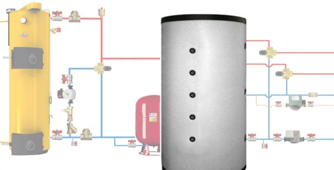
Tying a solid fuel boiler and a buffer tank
The simplest will be a piping scheme containing a buffer tank with a pre-installed DHW coil. The advantage of this option will be significant savings in space in the boiler room due to the absence of a separate boiler. Another additional plus is a modest investment savings due to the absence of the need to buy and install another node. This option simplifies the process of maintaining the system, since there will be no problems with the fight against bacteria.
Storage tank connection diagrams
Connecting a properly selected battery makes it possible to reduce the cost of purchasing fuel (up to 50%) and allows you to switch to the mode of one load per day instead of two.
If the unit is equipped with intelligent regulators and temperature sensors, and the supply of heat from the storage tank to the heating system is automated, heat transfer will increase significantly, and the number of portions of fuel loaded into the combustion chamber of the heating apparatus will be much reduced.
There are many options for piping a solid fuel boiler with a heat accumulator and a heating system. However, they are all derivatives of the basic schema. With its help, it is easy to understand how these devices function in pairs, and then assemble everything with your own hands.
The TT boiler has a traditional boiler circuit with a mixing unit, whose task is to prevent the supply of cold heat carrier to the heat source. Then the supply and return pipelines are connected to the buffer tank, respectively, from the top and bottom.
In the same way, the heating system, also equipped with a mixing unit, is connected to the accumulator. Its purpose is to maintain the required water temperature in the system, mixing part of the hot coolant if necessary.
Basic diagram for connecting a heat accumulator:
An important point! The practical performance of the boiler circuit circulation pump should be slightly higher than that of the pumping equipment of the heating network. This will allow the liquid inside the container to move in the correct direction.
But in fact, the network pump will be more powerful than the boiler one, because the resistance of the network of pipelines and radiators is higher than 3-5 m of pipes from the solid fuel boiler to the buffer tank. Higher power and head are required for the device to overcome this resistance. Therefore, a weaker boiler circuit pump will be able to provide a higher flow, you just need to correctly adjust both mechanisms.
There are two options for solving this problem:
- In the case of using 3-speed pumps, you can adjust their performance by switching speeds.
- Put a balancing valve at the inlet of the return from the system to the buffer tank, which is used to adjust.
Parallel heating of radiators and layer-by-layer loading of the storage tank are possible when the flows inside the tank move horizontally with a slight predominance from the side of the solid fuel boiler. To check this, it is necessary to install thermometers on both inlets of the return to the tank and make adjustments by switching the speed of the pumps or rotating the balancing valve. In this case, the three-way valve of the heating network must be fully opened manually.
By adjusting it is necessary to ensure that the temperature at the inlet to the heat accumulator (T1) is less than at its outlet (T2). This means that some of the hot water is used to "charge" the battery.
Alternative scheme. The peculiarity of this method of piping a buffer tank and a solid fuel boiler is that when the power supply is turned off, the system remains operational, although this has to be paid for with increased diameters of steel pipes.
Alternative connection of the heat accumulator to the heating system:
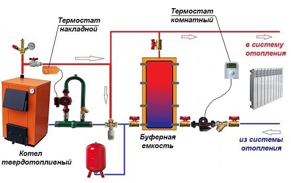
Attention! The picture shows the connection of the buffer tank to a closed heating system, but it is better to make it open during installation.
The bottom line is as follows: thanks to the T-shaped inlet on top of the tank, the radiators are heated synchronously and the storage is "charged". The boiler circuit pump is controlled by a plug-on sensor on the flow line, turning on the device after reaching a temperature of 60 ° C. The circulation in the network depends on the room thermostat to which the network pump is connected.
Simple switching circuit with admixture
The storage device can be included in the system in different ways. The simplest piping of a solid fuel boiler with a heat accumulator is suitable for working with gravitational coolant supply systems and will operate in the event of a power outage. For this, the tank must be installed above the heating radiators. The circuit includes a circulation pump, a thermostatic three-way valve and a non-return valve. At the start of the heating cycle, water driven by the pump flows through the supply line from the heat source through the three-way valve to the heaters. This continues until the flow temperature reaches a certain value, for example 60 ° C.
At this temperature, the valve begins to mix cold water into the system from the lower branch pipe of the tank, observing the set temperature of 60 ⁰С at the outlet.Heated water will begin to flow into the tank through the upper branch pipe, directly connected to the boiler, and the battery will start charging. With complete combustion of wood in the firebox, the temperature in the supply pipe will begin to drop. When it drops below 60 ° C, the thermostat will gradually cut off the supply from the heat source and open the flow of water from the tank. That, in turn, will gradually be filled with cold water from the boiler and at the end of the cycle the three-way valve will return to its original position.
The non-return valve, connected in parallel with the three-way thermostat, is activated when the circulation pump is stopped. Then the boiler with the heat accumulator will work directly, the coolant will go to the heating devices directly from the tank, which will be replenished with water from the heat source. In this case, the thermostat does not take part in the operation of the circuit.
How to make a heat accumulator with your own hands?
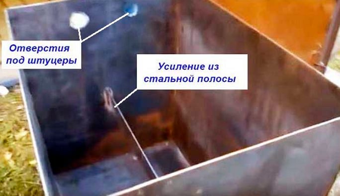
The most simplified modification of the heat storage device can be made with your own hands from an ordinary steel barrel. If such a tank is not available, then you can buy several sheets of stainless steel with a thickness of at least 2 mm and weld a suitable tank from them in the form of a vertical cylindrical tank container.
Diy heat accumulator assembly algorithm:
- Cut workpieces from stainless steel to size and weld the body without a bottom and a cover on tacks. Use clamps and a square to fix the sheets.
- Next, you need to cut holes in the side walls for stiffness. Insert the prepared pipes inside and scald their ends from the outside.
- Grab the bottom with a lid to the tank. Cut holes in them and repeat the operation with the installation of internal stretch marks.
- When all opposite walls of the tank are securely connected to each other, you can start continuous welding of all seams.
- Then it is necessary to install supports on the product from pipe sections.
- Embed the fittings, stepping back from the bottom and cover by less than 10 cm, as shown in the drawing.
- Weld metal brackets to the walls, which will serve as brackets for attaching heat-insulating material and cladding.
After welding all parts of the unit, you need to check it for leaks. To do this, the container must be filled with water or lubricated with kerosene welds. If no leak is found, then you can proceed to creating an insulating layer that will allow the liquid inside the tank to remain hot for as long as possible.
First, the outer surface of the tank must be thoroughly cleaned and degreased, then primed and painted with heat-resistant powder paint to protect the drive from corrosion processes. Then you need to wrap the container with insulation or rolled basalt wool 6-8 mm thick and secure it with cords or ordinary tape. If you wish, you can cover the surface with sheet metal or "wrap" the battery in foil film.
In the outer layer, it is necessary to cut holes for the branch pipes and connect a homemade buffer tank to the boiler and heating system. The storage tank must be equipped with a thermometer, internal pressure sensors and an explosion valve. These components make it possible to control the potential for overheating of the reservoir and to relieve excess pressure periodically.
Safe use rules
Do-it-yourself home-made heat accumulators are subject to particularly stringent requirements for safe operation:
- Hot parts of the container must not adjoin or otherwise come into contact with flammable and explosive materials and substances. Ignoring this point can provoke the ignition of individual items and lead to a fire in the boiler room.
- A closed heating system implies a constant high pressure of the coolant circulating inside.For this, the design of the buffer tank must be completely sealed. Additionally, its body can be reinforced with stiffening ribs, and the lid on the tank can be equipped with durable rubber gaskets that are resistant to intense operating loads and high temperatures.
- If an additional heating element is present in the structure, it is required to very carefully insulate its contacts, and the tank must be grounded. In this way, it will be possible to avoid electric shock and short circuits, which can damage the entire system.
Subject to these rules, the use of a self-assembled heat accumulator according to the working scheme will be completely safe and will not cause any problems and hassle to the owners.
Thus, the website "Plumber Portal" leaves no doubt that the heat accumulator for the boiler significantly improves the operating conditions of the device. The solid fuel unit burns firewood with maximum efficiency, and after warming up, the number of trips to the boiler room is reduced to a minimum. However, this factory-made device is not a cheap pleasure, so most batteries in private houses are made by hand or to order from craftsmen.