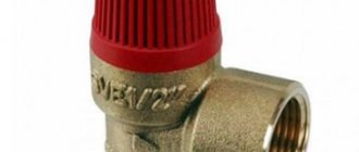
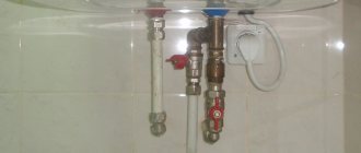
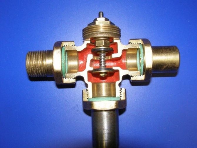
Four-way valve design
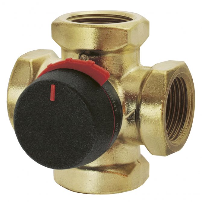
The body is made of brass, 4 connecting pipes are attached to it. Inside the body there is a bushing and a spindle, the operation of which has a complex configuration.
The thermostatic mixing valve performs the following functions:
- Mixing water streams of different temperatures. Thanks to mixing, smooth regulation of water heating works;
- Boiler protection. The four-way mixer prevents corrosion, thus extending the life of the equipment.
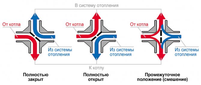
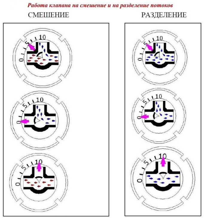
Four-way mixer circuit
The principle of operation of such a valve for heating is to rotate the spindle inside the body. Moreover, this rotation must be free, since the sleeve has no thread. The working part of the spindle has two cuts through which the flow is opened in two passes. Thus, the flow will be regulated and will not be able to go directly to the second sample. The flow will be able to turn into any of the nozzles located on the left or right side of it. So, all streams coming from opposite sides are mixed and distributed over four nozzles.
There are designs in which a push rod works instead of a spindle, but such devices cannot mix flows.
The valve is controlled in two ways:
- Manual. Distribution of flows requires the installation of the stem in one specific position. You need to adjust this position manually.
- Auto. The spindle rotates as a result of a command received from an external encoder. In this way, the set temperature is constantly maintained in the heating system.
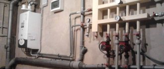
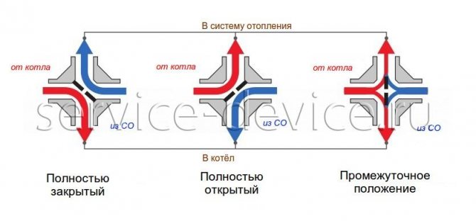
The four-way mixing valve ensures a stable flow rate of cold and hot heating medium. The principle of its operation does not require the installation of a differential bypass, because the valve itself passes the required amount of water. The device is used where temperature control is required. First of all, it is a radiator heating system with a solid fuel boiler. If in other cases the regulation of heat carriers occurs with the help of a hydraulic pump and a bypass, then here the operation of the valve completely replaces these two elements. As a result, the boiler operates in a stable mode, constantly receiving a dosed amount of coolant.
Heating with four-way valve
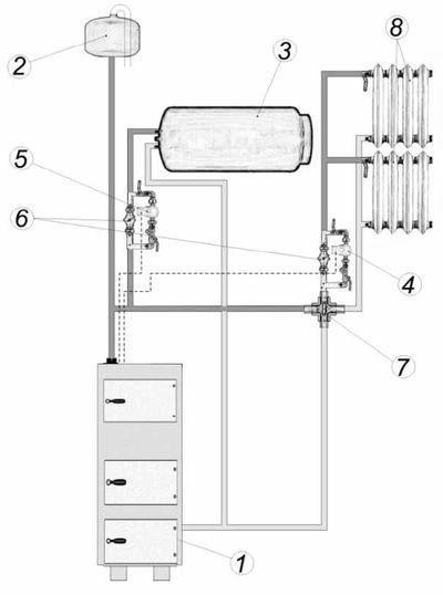
Installation of a heating system with a four-way valve:

Circulation pump connection. Installed on the return pipe;- Installation of safety lines on the inlet and outlet pipes of the boiler. Do not install valves and taps on safety lines, as they are under high pressure;
- Installation of a non-return valve on the water supply pipe. The principle of operation is aimed at protecting the heating system from the influence of back pressure and siphon drainage;
- Expansion tank installation. Installed at the highest point of the system. This is necessary in order not to hinder the operation of the boiler during the expansion of water. The expansion tank is fully functional both in horizontal and vertical position;
- Installation of a safety valve. The thermostatic valve is installed on the water supply pipe. It is designed to evenly distribute energy for heating. This device has a dual sensor. When the temperature rises above 95 ° C, this sensor sends a signal to the thermostatic mixer, as a result of which a flow of cold water opens. After the system has cooled down, a second signal is sent to the sensor, which completely closes the tap and stops the supply of cold water;
- Installation of a pressure reducer. Placed in front of the entrance to the thermostatic mixer.The principle of operation of the reducer is to minimize pressure drops during water supply.
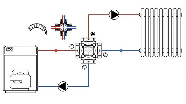
The connection diagram of a heating system with a four-way mixer consists of the following elements:
- Boiler;
- Four-way thermostatic mixer;
- Safety valve;
- Reducing valve;
- Filter;
- Ball valve;
- Pump;
- Heating batteries.
The installed heating system must be flushed with water. This is necessary so that various mechanical particles are removed from it. After that, the boiler operation must be checked at a pressure of 2 bar and with the expansion vessel switched off. It should be noted that a short period of time must elapse between the start of the full operation of the boiler and its check under hydraulic pressure. The time limit is due to the fact that with a long absence of water in the heating system, it will corrode.
To constantly maintain a comfortable thermal balance in the house, an element such as a three-way valve on the heating system is included in the heating circuit, which evenly distributes heat to all rooms.
Despite the importance of this unit, it does not differ in its complex design. Let's take a look at the design features and principles of the three-way valve. What rules should be followed when choosing a device and what nuances are present in its installation.
Features of the three-way valve
The water supplied to the radiator has a certain temperature, which is often not possible to influence. The three-way valve regulates by changing not the temperature, but the amount of liquid.
This makes it possible, without changing the area of the radiator, to supply the rooms with the required amount of heat, but only within the limits of the power of the system.
Separating and mixing devices
Visually, the three-way valve resembles a tee, but performs completely different functions. Such a unit, equipped with a thermostat, belongs to shut-off valves and is one of its main elements.
There are two types of these devices: separation and mixing.
The first is used when the coolant must be supplied simultaneously in several directions. In fact, the unit is a mixer that forms a stable flow with a set temperature. It is mounted in a network through which heated air is supplied, and in water supply systems.
Products of the second type are used to combine flows and their thermoregulation. There are two openings for incoming streams with different temperatures, and one for their outlet. They are used when installing underfloor heating to prevent overheating of the surface.
What is a three-way valve and what is it for in a heating system
The three-way valve has a body with three nozzles. One of them never overlaps. And the other two can alternately overlap partially or completely. It depends on the configuration of the thermal valve. Moreover, if one branch pipe is completely closed, then the second is completely open.
The three-way control valve has two options for its intended purpose: for mixing and for separation. Some models can be used for both types of work, it depends on how they are installed.
The fundamental difference between three-way valves and three-way valves is that the valve regulates mixing or separation of flows, but cannot shut them off completely, except for one of the two. The valve is not used to shut off flows.
A three-way valve, on the other hand, cannot regulate mixing or separation of streams. It can only redirect the flow in the other direction or completely shut off one of the 3 nozzles.
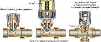
As a rule, three-way valves are equipped with actuators that allow to automatically change the position of the overlapping segment in order to maintain the given parameters. But they can also have a manual drive.
Sometimes the stem is made in the form of a worm thread, typical for valves. There are two valves on the stem. Because of this similarity, they are sometimes also referred to as a three-way valve.
Interesting: sometimes the stem is made in the form of a worm thread, typical for valves. There are two valves on the stem. Because of this similarity, they are sometimes also called a three-way valve.
The principle of operation of the three-way valve mixing and dividing type VALTEK VT.MIX03
Before the advent of three-way valves, boiler houses supplied separately hot water and heat carrier to the network for heating. 4 main pipes came out of the boiler room. The invention of the three-way mechanism made it possible to switch to two-pipe lines. Now the network was supplied only with a heat carrier with a constant temperature of 70 - 900, in some systems 90 - 1150. And hot water and a heat carrier for heating the building were prepared at the entrance to a residential building in an individual heating station (ITP).
The savings in metal, in the form of reducing 2 pipes in the main lines, turned out to be colossal. And also the simplification of the work of boiler rooms, and their automation, which increased reliability. Reducing the cost of maintaining backbone networks And the possibility of separating the backbone networks from the intra-house ones, in order to localize possible accidents in the intra-house networks.
Three-way valves were further developed and began to be used not only in heating points, but also in rooms, to regulate the temperature of heating devices.
Where are 3-way valves used?
There are valves of this type in different schemes. They are included in the wiring diagram of underfloor heating to ensure uniform heating of all its sections and to exclude overheating of individual branches.
In the case of a solid fuel boiler, condensation is often observed in its chamber. The installation of a three-way valve will help to deal with it.
A three-way device in the heating system works effectively when there is a need to connect a DHW circuit and separate heat flows.
The use of a valve in the piping of radiators eliminates the need for a bypass. Installing it on the return line creates conditions for a short circuit device.
Advantages and disadvantages
The main advantage of three-way valves is the ability to automatically regulate the parameters of the coolant.
Before the advent of three-way devices, elevator units were used to regulate the temperature of the coolant in the heating system of the building. The accuracy of their tuning was very rough. For each building it was necessary to calculate the cross-section of the elevator nozzle opening. It changed over time.
With the advent of three-way valves, these assemblies are a thing of the past, and there is simply no alternative to them today. Instead of one 3-way device, it is possible to put two simple adjustable valves for supply and make-up from the return flow. What was done in the transition period after the elevator units. But such schemes are much more expensive and more difficult to manage. Therefore, they were quickly abandoned.
In the case of regulating the flow of the heating medium through the heating radiator, on the contrary, simple control valves have an advantage over 3-way valves. After all, the bypass section in front of the battery does not need to be closed and even harmful. Therefore, a simple regulating device, or also called a thermostatic valve, is placed behind the bypass in front of the radiator and it is cheaper and more reliable. Nevertheless, three-way valves can be found in individual buildings in front of the batteries.
The nuances of choosing a device
The following guidelines are common when choosing a suitable 3-way valve:
- Reputable manufacturers are preferred. Often on the market there are low-quality valves from unknown companies.
- Copper or brass products are more wear-resistant.
- Manual controls are more reliable, but less functional.
The key point is the technical parameters of the system in which it is supposed to be installed. The following characteristics are taken into account: the pressure level, the highest temperature of the coolant at the point of installation of the device, the permissible pressure drop, the volume of water passing through the valve.
Only a properly sized valve will work well. To do this, you need to compare the performance of your plumbing system with the coefficient of throughput of the device. It is mandatory marked on each model.
For rooms of limited area, such as a bathroom, it is irrational to choose an expensive valve with a thermo mixer.
On large areas with warm floors, a device with automatic temperature control is required. The reference for selection should also be the conformity of the product GOST 12894-2005.
The cost can be very different, it all depends on the manufacturer.
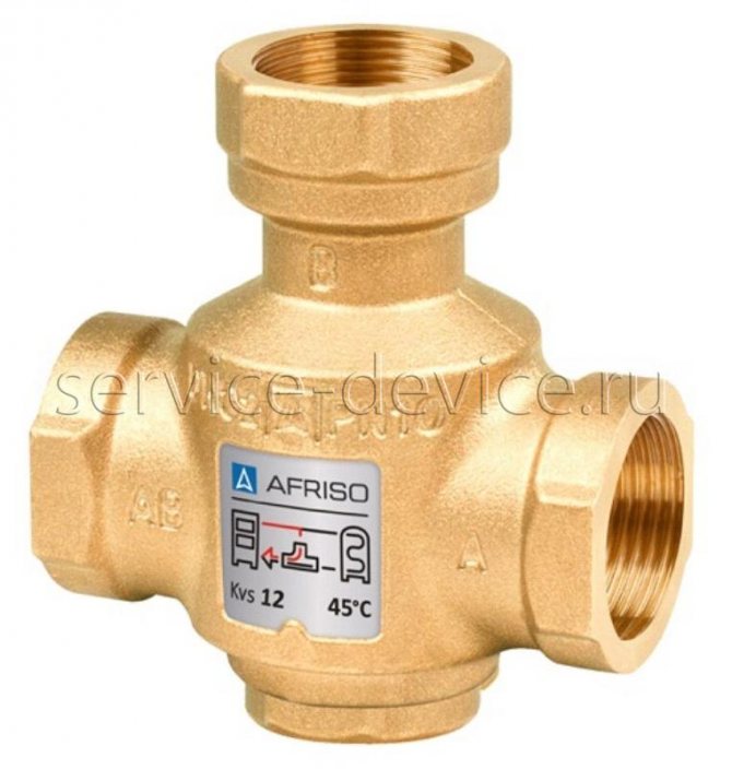
In country houses with an installed solid fuel boiler, the heating scheme is not very complicated. A three-way valve with a simplified design is fine here.
It functions autonomously and does not have a thermal head, sensor, or even a rod. The thermostatic element that controls its operation is set to a certain temperature and is located in the housing.
Nominal diameter of the control valve
Control valves are never sized according to the pipeline diameter. However, the diameter must be determined for sizing control valves. Since the control valve is selected according to the Kvs value, the nominal diameter of the valve is often less than the nominal diameter of the pipeline on which it is installed. In this case, it is allowed to choose a valve with a nominal diameter less than the nominal diameter of the pipeline by one or two steps.
Determination of the calculated valve diameter is carried out according to the formula:
- d is the estimated valve diameter in, mm;
- Q is the flow rate of the medium, m3 / hour;
- V is the recommended flow rate m / s.
Recommended flow rate:
- liquid - 3 m / s;
- saturated steam - 40 m / s;
- gas (at pressure <0.001 MPa) - 2 m / s;
- gas (0.001 - 0.01 MPa) - 4 m / s;
- gas (0.01 - 0.1 MPa) - 10 m / s;
- gas (0.1 - 1.0 MPa) - 20 m / s;
- gas (> 1.0 MPa) - 40 m / s;
According to the calculated value of the diameter (d), the nearest larger nominal diameter of the DN valve is selected.
Three Way Instrument Manufacturers
There is a wide range of three-way valves on the market from both reputable and unknown manufacturers. The model can be selected after the general parameters of the product have been determined.
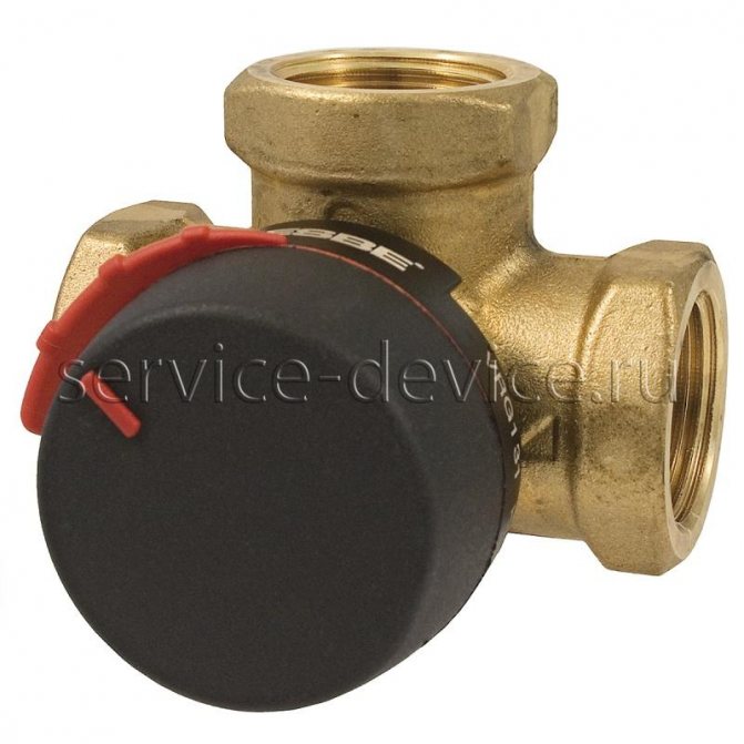
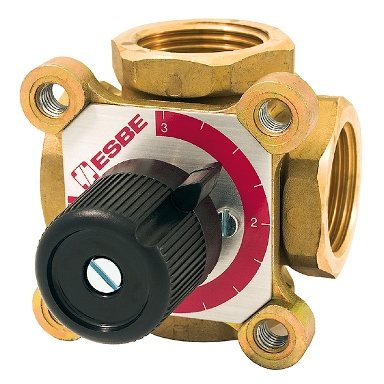
The first place in the sales ranking is occupied by valves of the Swedish company Esbe... This is a fairly well-known brand, so three-way products are reliable and durable.
Among consumers, three-way valves of a Korean manufacturer are known for their quality. Navien... They should be purchased if you have a boiler from the same company.
Greater control accuracy is achieved by installing a Danish company device Danfoss... It works completely automatically.
Valves are distinguished by good quality and affordable cost Valtec, manufactured jointly by specialists from Italy and Russia.
Products of a company from the USA are effective in work Honeywell... These valves are simple in structure and easy to install.
Features of product installation
During the installation of three-way valves, many nuances arise. The uninterrupted functioning of the heating system depends on their accounting. The manufacturer encloses instructions for each valve, the observance of which will subsequently avoid many troubles.
General installation guidelines
The main thing is to initially set the valve in the correct position, guided by the prompts indicated by the arrows on the body. Pointers indicate the path of the water flow.
A stands for direct travel, B stands for perpendicular or bypass direction, AB stands for combined input or output.
Based on the direction, there are two valve models:
- symmetrical or T-shaped;
- asymmetrical or L-shaped.
When mounted along the first of them, the liquid enters the valve through the end holes. Leaves through the center after mixing.
In the second variant, a warm stream enters from the end, and a cold stream enters from below. The liquid at different temperatures is discharged after mixing through the second end.
The second important point when installing the mixing valve is that it must not be positioned with the actuator or thermostatic head down. Before starting work, preparation is necessary: water is cut off in front of the installation point. Next, check the pipeline for the presence of residues in it that can cause the valve gasket to fail.
The main thing is to choose a place for installation so that the valve has access. It may have to be checked or dismantled in the future. All this requires free space.
Mixing valve insert
When inserting a three-way mixing valve into a district heating system, there are several options. The choice of the scheme depends on the nature of the connection of the heating system.
When, according to the operating conditions of the boiler, such a phenomenon as overheating of the coolant in the return is permissible, an overpressure necessarily arises. In this case, a jumper is mounted that throttles the excess head. It is installed parallel to the valve mix.
The diagram in the photo is a guarantee of high-quality regulation of the system parameters. If the three-way valve is connected directly to the boiler, which is most often the case in autonomous heating systems, a balancing valve insert is required.
If the recommendation for installing a balancing device is disregarded, significant changes in the flow rate of the working fluid, depending on the position of the stem, can occur in the AB port.
Connection according to the above diagram does not guarantee the absence of circulation of the coolant through the source. To achieve this, it is necessary to additionally connect a hydraulic isolator and a circulation pump to its circuit.
The mixing valve is also installed in order to separate the flows. The need for this arises when it is unacceptable to completely isolate the source circuit, but bypassing the liquid into the return is possible. Most often, this option is used in the presence of an autonomous boiler room.
Please be aware that vibration and noise may occur with some models. This is due to inconsistent flow directions in the pipeline and the mixing article. As a result, the pressure across the valve may drop below the permissible value.
Installing the separating device
When the temperature of the source is higher than required by the consumer, a valve separating the flows is included in the circuit. In this case, at a constant flow rate both in the boiler circuit and by the consumer, the overheated liquid will not come to the latter.
For the circuit to work, a pump must be present in both circuits.
Based on the above, general recommendations can be summarized:
- When installing any three-way valve, manometers are installed before and after it.
- To avoid the ingress of any impurities, a filter is mounted in front of the product.
- The body of the device must not be subjected to any stress.
- Good regulation must be ensured by inserting overpressure throttling devices in front of the valve.
- The valve must not be above the actuator during installation.
It is also necessary to maintain in front of the product and after it the straight sections recommended by the manufacturer. Failure to comply with this rule will result in a change in the declared technical characteristics. The device will not be covered by the warranty.
Repairman's guide
| 52.Four-way cycle reversal solenoid valve |
During the 1973 oil crisis, the demand for the installation of a large number of heat pumps increased dramatically. Most heat pumps are equipped with a four-way cycle reversal solenoid valve used to either set the pump to summer mode (cooling) or to cool the outdoor coil in winter mode (heating). The subject of this section is to explore the operation of the four-way cycle reversal solenoid valve (V4V) found on most classic air-to-air heat pumps and cycle reversal defrost systems (see figure 60.14) to effectively control direction of travel. streams. A) V4V operation Let's study the diagram (see fig. 52.1) of one of these valves, consisting of a large four-way main valve and a small three-way pilot valve mounted on the main valve body. At the moment we are interested in the main four-way valve. First, note that of the four main valve connections, three are located next to each other (the compressor suction line is always connected to the middle of these three connections), and the fourth connection is on the other side of the valve (the compressor discharge line is connected to it). Note also that on some V4V models the suction connection may be offset from the center of the valve. 'T \ However, the discharge (pos. 1) and suction- \ 3J (pos. 2) lines of the compressor are ALWAYS connected as shown in the diagram fig. Inside the main valve, communication between the various channels is ensured by means of a movable spool (pos. 3), sliding together with two pistons (item 4). Each piston has a small hole drilled (key 5) and in addition each piston has a needle (key 6). Finally, 3 capillaries (item 7) are cut into the main valve body at the locations shown in fig. 52.1, which are connected to the control solenoid valve, if you do not study the principle of operation of the valve perfectly. Each element presented by us plays a role in the V4V operation. That is, if at least one of these elements fails, it can be the cause of a very difficult to detect malfunction- Let's now consider how the main valve works ... If V4V is not mounted on the installation, when you apply voltage to the solenoid valve, you will expect a distinct click, but the spool will not move. Indeed, in order for the spool inside the main valve to move, it is absolutely necessary to provide a differential pressure across the spool. Why so, we will see now. The discharge Pnag and suction Pvsac lines of the compressor are always connected to the main valve as shown in the diagram {fig. 52.2). At the moment, we will simulate the operation of a three-way control solenoid valve using two manual valves: one closed (pos. 5) and the other open (pos. 6). In the center of the main valve, Pnag develops forces acting on both pistons in the same way: one pushes the spool to the left (pos. 1), the other to the right (pos. 2), as a result of which both these forces are mutually balanced. Recall that small holes are drilled in both pistons. Therefore, Pnag can pass through the hole in the left piston, and Pnag will also be installed in the cavity (pos. 3) behind the left piston, which pushes the spool to the right. Of course, at the same time Rnag also penetrates through the hole in the right piston into the cavity behind it (pos. 4). However, since valve 6 is open, and the diameter of the capillary connecting the cavity (item 4) with the suction line is much larger than the diameter of the hole in the piston, gas molecules passing through the hole will instantly be sucked into the suction line. Therefore, the pressure in the cavity behind the right piston (pos. 4) will be equal to the pressure Pvsac in the suction line.Thus, a more powerful force due to the action of Pnag will be directed from left to right and will cause the spool to move to the right, communicating the non-melting line with the left choke (pos. 7), and the suction line with the right choke (pos. 8). If now Pnag is directed into the cavity behind the right piston (close valve 6), and Pvac into the cavity behind the left piston (open valve 5), then the prevailing force will be directed from right to left and the spool will move to the left (see Fig.52.3). At the same time, it communicates the delivery line with the right-hand union (item 8), and the suction line with the left-hand union (item 7), that is, exactly the opposite as compared to the previous version. Of course, the use of two manual valves for the reversibility of the operating cycle cannot be envisaged. Therefore, now we will begin to study a three-way control solenoid valve, which is most suitable for automating the cycle reversal process. We have seen that the movement of the spool is possible only if there is a difference between the values of Pnag and Pvsac. The three-way solenoid valve is designed only to release pressure from either one or the other supply cavity of the main valve pistons. Therefore, the control solenoid valve will be very small and will remain the same for all diameters of the main valve. The central inlet of this valve is a common outlet and connects to the suction cavity {see. fig. 52.4). If voltage is not applied to the winding, the right inlet is closed, and the left one communicates with the suction cavity. Conversely, when voltage is applied to the winding, the right inlet is in communication with the suction cavity, and the left one is closed. Let us now examine the simplest refrigeration circuit equipped with a four-way valve V4V (see fig. 52.5). The solenoid winding of the control solenoid valve is not energized and its left inlet communicates the cavity of the main valve, behind the left piston of the spool, with the suction line (recall that the diameter of the hole in the piston is much smaller than the diameter of the capillary connecting the suction line with the main valve). Therefore, in the cavity of the main valve, to the left of the left piston of the spool, Pvsac is installed. Since Pnag is installed to the right of the spool, under the influence of the pressure difference, the spool moves sharply inside the main valve to the left. Having reached the left stop, the piston needle (pos. A) closes the hole in the capillary connecting the left cavity with the Pvsac cavity, thereby preventing the passage of gas, since this is no longer necessary. In fact, the presence of constant leakage between the cavities Pnag and Pvsac can only have a harmful effect on the operation of the compressor.Note that the pressure in the left cavity of the main valve again reaches the value of Pnag, but since Pnag is also established in the right cavity, the spool will no longer be able to change your position. Now let us remember the location of the condenser and evaporator, as well as the direction of flow in the capillary expansion device. Before continuing reading, try to imagine what will happen if voltage is applied to the solenoid valve coil. When power is applied to the solenoid valve coil, the right cavity of the main valve communicates with the suction line and the spool moves sharply to the right. Having reached the stop, the piston needle interrupts the outflow of gas into the suction line, blocking the opening of the capillary connecting the right cavity of the main valve with the suction cavity. As a result of the movement of the spool, the delivery line is now directed towards the former evaporator, which has become the condenser. Likewise, the former condenser has become an evaporator and the suction line is now connected to it. Note that the refrigerant in this case moves through the capillary in the opposite direction (see fig. 52.6).To avoid mistakes in the names of heat exchangers, which alternately become an evaporator, then a condenser, it is best to call them an external battery (an outdoor heat exchanger) and an internal battery (an indoor heat exchanger). B) Risk of water hammer During normal operation, the condenser is filled with liquid. However, we saw that at the moment of cycle reversal, the condenser almost instantly becomes the evaporator. That is, at this moment there is a danger of a large amount of liquid entering the compressor, even if the expansion valve is completely closed. To avoid this hazard, it is usually necessary to install a liquid separator on the suction line of the compressor. The liquid separator is designed in such a way that in the event of an overflow of liquid at the outlet of the main valve, mainly during the reversal of the cycle, it is prevented from entering the compressor. The liquid remains at the bottom of the separator, while the pressure is taken into the suction line at its highest point, which completely eliminates the risk of liquid entering the compressor. However, we have seen that the oil (and therefore the liquid) must constantly return to the compressor through the suction line. To give the oil such an opportunity, a calibrated hole (sometimes a capillary) is provided at the bottom of the suction pipe ... When liquid (oil or refrigerant) is retained at the bottom of the liquid separator, it is sucked through the calibrated hole, slowly and gradually returning to the compressor in such quantities that turn out to be insufficient to lead to undesirable consequences. C) Possible malfunctions One of the most difficult V4 V valve malfunctions is associated with a situation where the spool is stuck in an intermediate position (see fig. 52.8). At this moment, all four channels communicate with each other, which leads to a more or less complete, depending on the position of the spool when jammed, bypassing gas from the discharge line into the suction cavity, which is accompanied by the appearance of all signs of a malfunction of the "too weak compressor" type: a decrease in ho - capacity, drop in condensing pressure, increase in evaporating pressure (see section 22. "Compressor too weak"). Such seizure can occur accidentally and is due to the very design of the main valve. Indeed, since the spool can move freely within the valve, it can move and, instead of being at one of the stops, remain in an intermediate position due to vibrations or mechanical shock (for example, after transportation).
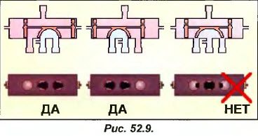
If the V4V valve is not yet installed and, therefore, it is possible to hold it in hands, the installer MUST check the position of the spool by looking inside the valve through the 3 lower holes (see fig. 52.9). In this way, it can very easily ensure the normal position of the spool, because after the valve is soldered it will be too late to look inward! If the spool is positioned incorrectly (fig. 52.9, right), it can be brought into the desired state by tapping one end of the valve on a block of wood or a piece of rubber (see fig. 52.10). Never knock the valve on a metal part, as doing so you risk damaging the end of the valve or completely destroying it. With this very simple technique, you can, for example, set the V4V valve spool to the cooling position (the delivery line communicates with an external heat exchanger) when replacing a faulty V4V with a new one in a reversible air conditioner (if this happens in high summer). Multiple structural defects in the main valve or auxiliary solenoid valve can also cause the spool to jam in the intermediate position.For example, if the main valve body is damaged by impacts and deforms in the barrel, this deformation will prevent the spool from moving freely. One or more capillaries connecting the cavities of the main valve with the low-pressure part of the circuit can become clogged or bent, which will lead to a decrease in their flow area and will not allow a sufficiently rapid release of pressure in the cavities behind the pistons of the spool, thereby disrupting its normal operation (recall also times that the diameter of these capillaries should be substantially larger than the diameter of the holes drilled in each of the pistons). Traces of excessive burnout on the valve body and poor appearance of the soldered joints are an objective indicator of the qualifications of an installer who soldered with a gas torch. Indeed, during brazing, it is imperative to protect the main valve body from heating by wrapping it in a wet rag or soaked in asbestos paper, since the pistons and the spool are equipped with sealing nylon (fluoroplastic) rings, which simultaneously improve the slide of the spool inside the valve. When soldering, if the temperature of the nylon exceeds 100 ° C, it loses its sealing and anti-friction characteristics, the gasket gets irreparable damage, which greatly increases the likelihood of the spool jamming at the first attempt to switch the valve. Recall that the rapid movement of the spool during cycle reversal occurs under the influence of the difference between Pnag and Pvsac. Consequently, the movement of the spool becomes impossible if this difference AP is too small (usually its minimum allowable value is about 1 bar). Thus, if the control solenoid valve is activated when the AP differential is insufficient (for example, when starting the compressor), the spool will not be able to move unhindered and there is a danger of its jamming in the intermediate position. Spool sticking can also occur due to malfunctions of the control solenoid valve, for example, due to insufficient supply voltage or improper installation of the electromagnet mechanism. Note that dents on the electromagnet core (due to impacts) or its deformation (during disassembly or as a result of falling) do not allow the core sleeve to slide normally, which can also lead to valve seizure. It is worth reminding that the condition of the refrigeration circuit must be absolutely perfect. Indeed, if the presence of copper particles, traces of solder or flux is extremely undesirable in a conventional refrigeration circuit, then even more so for a circuit with a four-way valve. They can jam it or block the piston bores and capillary passages of the V4V valve. Therefore, before proceeding with the dismantling or assembly of such a circuit, try to think through the maximum precautions that you must observe. Finally, it should be emphasized that the V4V valve is highly recommended to be mounted in a horizontal position to avoid even a slight lowering of the spool by its own weight, as this can cause constant leakage through the upper piston needle when the spool is in the up position. Possible causes of spool jamming are shown in Fig. 52.11. Now the question arises. What to do if the spool is stuck? Before requesting normal operation of the V4V valve, the repairer must first ensure the conditions for this operation on the side of the circuit. For example, a lack of refrigerant in the circuit, causing a drop in both Pnag and Pvsac, may result in a weak differential pressure drop, insufficient for a free and complete overflow of the spool.If the appearance of V4V (no dents, traces of impacts and overheating) seems satisfactory and there is confidence that there are no electrical faults (very often such faults are attributed to the V4V valve, while we are talking only about electrical defects), the repairer should ask the following question: To which heat exchanger (internal or external) should the compressor discharge line be suitable and in what position (right or left) should the spool be located for a given operating mode of the installation (heating or cooling) and its given design (heating or cooling with de-energized control solenoid valve)? When the repairman has confidently determined the required normal position of the spool (right or left), he can try to put it in place, lightly but sharply, tapping on the main valve body from the side where the spool should be located with a mallet or a wooden hammer (if there is no mallet, never use a regular hammer or hammer without first attaching a wooden spacer to the valve, otherwise you risk seriously damaging the valve body, see fig. 52.12). In the example in Fig. 52.12 hitting the mallet from the right forces the spool to move to the right (unfortunately, the developers, as a rule, do not leave space around the main valve to strike!). Indeed, the compressor discharge pipe must be very hot (beware of burns, as in some cases its temperature can reach 10 ° C). The suction pipe is usually cold. Therefore, if the spool is shifted to the right, the nozzle 1 should have a temperature close to the temperature of the discharge pipe, or, if the spool is shifted to the left, close to the temperature of the suction pipe. We have seen that a small amount of gases from the discharge line (hence, very hot) passes during a short period of time, when the spool overflow occurs, through two capillaries, one of which connects the cavity of the main valve on the side where the spool is located, with one of the of the solenoid valve inputs, and the other connects the output of the control solenoid valve to the suction line of the compressor. Further, the passage of gases stops, since the needle of the piston, which has reached the stop, closes the opening of the capillary and prevents gases from entering it. Therefore, the normal temperature of the capillaries (which can be touched with your fingertips), as well as the temperature of the body of the control solenoid valve, should be almost the same as the temperature of the body of the main valve. If groping gives other results, there is no choice but to try to understand them. Suppose, during the next maintenance, the repairer discovers a slight increase in the suction pressure and a slight drop in the discharge pressure. Since the lower left fitting is hot, it infers that the spool is on the right. Feeling the capillaries, he notices that the right capillary, as well as the capillary connecting the outlet of the solenoid valve with the suction line, have an elevated temperature. Based on this, he can conclude that there is a constant leakage between the pressure and suction cavities and, therefore, the needle of the right piston does not provide tightness (see Fig. 52.14). He decides to increase the discharge pressure (for example, covering part of the condenser with cardboard) in order to increase the pressure difference and thereby try to press the spool against the right stop. Then he moves the spool to the left to ensure that the V4V valve is working properly, and then returns the spool to its original position (increasing the discharge pressure if the pressure difference is insufficient, and checking the response of V4V to the operation of the control solenoid valve). Thus, on the basis of these experiments, he can draw appropriate conclusions (in the event that the leakage rate continues to remain significant, it will be necessary to provide for the replacement of the main valve).The discharge pressure is very low and the suction pressure is abnormally high. Since all four V4V fittings are quite hot, the technician concludes that the spool is stuck in the intermediate position. Feeling the capillaries shows the repairer that all 3 capillaries are hot, therefore the cause of the malfunction lies in the control valve, in which both flow sections were simultaneously open. In this case, you should completely check all the components of the control valve (mechanical installation of the electromagnet, electrical circuits, supply voltage, current consumption, condition of the electromagnet core) and try repeatedly, turning the valve on and off, return it to working condition, removing possible foreign particles from under one or both of its seats (if the defect persists, the control valve will need to be replaced). Regarding the control valve solenoid coil (and in general, any solenoid valve coils), some novice repairers would like some advice on how to determine if the coil is working or not. Indeed, in order for the coil to excite a magnetic field, it is not enough to apply voltage to it, since a wire break may occur inside the coil. Some installers install a screwdriver tip on the coil mounting screw to assess the strength of the magnetic field (however, this is not always possible), others remove the coil and monitor the core of the electromagnet, listening to the characteristic knock that accompanies its movement, and still others, after removing the coil, insert it into the hole for a screwdriver to make sure it is retracted by the magnetic force. Let's take this opportunity to make a little clarification ... As an example, consider the classic coil of a solenoid valve with the nom- ^ | nominal supply voltage of 220 V. As a rule, the developer allows a prolonged increase in voltage in relation to the nominal by no more than 10% (that is, about 240 volts), without the risk of excessive overheating of the winding and normal operation of the coil is guaranteed with a prolonged voltage drop no more than, than 15% (i.e. 190 volts). These tolerance limits for the supply voltage of the electromagnet are easy to explain. If the supply voltage is too high, the winding becomes very hot and may burn out. Conversely, at low voltages, the magnetic field is too weak to allow retraction of the core along with the valve stem inside the coil (see Section 55, Various Electrical Problems). If the supply voltage provided for our coil is 220 V, and the rated power is 10 W, we can assume that it will consume current I = P / U, that is, 1 = 10/220 = 0.045 Ar (or 45 mA). Voltage applied I = 0.08 A, Strong danger of coil burnout In fact, the coil will consume a current of about 0.08 A (80 mA), since for alternating current P = U x I x coscp, and for electromagnet coils coscp is usually close to 0.5. If the core is removed from the energized coil, the current consumption will increase to 0.233 A (that is, almost 3 times more than the nominal value). Since the heat released during the passage of current is proportional to the square of the current strength, this means that the coil will heat up 9 times more than under nominal conditions, which greatly increases the danger of its combustion. If you insert a metal screwdriver into a live coil, the magnetic field will pull it in and the current consumption will slightly drop (in this example, to 0.16 A, that is, twice the nominal value, see Fig. 52.16). Remember that you should never dismantle an electromagnet coil that is energized, as it can burn out very quickly.A good way to determine the integrity of the winding and check for the presence of supply voltage is to use a clamp meter (transformer clamp), which opens and pulls closer to the coil to detect the magnetic field generated by it during normal operation.If the coil is energized, the ammeter needle deflects. a change in the magnetic flux near the coil, allow, in the event of a malfunction, to register a sufficiently high value of the current on the ammeter (which, however, means absolutely nothing), which quickly gives confidence in the serviceability of the electrical circuits of the electromagnet. Note that the use of open transformer clamp meters is permissible for any windings supplied with alternating current (electromagnets, transformers, motors ...), at the moment when the tested winding is not in close proximity to another source of magnetic radiation.
| 52.1. Examples of using |
Exercise number 1 The repairer must replace the V4 V valve in the middle of winter with the installation shown in fig. 52.18. After draining the refrigerant from the installation and removing the faulty V4V, the repairer asks the following question: Bearing in mind that the outside and inside temperatures are low, the heat pump must work in the mode of heating the conditioned space. Before installing a new V4V, should the spool be positioned on the right, on the left, or is it irrelevant? As a hint, we present a diagram engraved on the body of the solenoid valve. Solution to exercise number 1 Upon completion of the repair, the heat pump should operate in heating mode. This means that the internal heat exchanger will be used as a condenser (see fig. 52.22). A study of the piping shows us that the V4V spool should be on the left. Therefore, the installer must ensure that the spool is actually on the left before installing a new valve. He can do this by looking inside the main valve through the three lower connection nipples. If necessary, move the spool to the left, either by tapping the left end of the main valve against a wooden surface, or lightly hitting the left end with a mallet. Fig. 52.22. Only then can the V4V valve be installed in the circuit (taking care to prevent excessive overheating of the main valve body when brazing). Now consider the designations on the diagram, which is sometimes applied to the surface of the solenoid valve (see Fig. 52.23). Unfortunately, such circuits are not always available, although they are very useful for V4V repair and maintenance. So, the spool was moved by the repairman to the left, while it is better that at the time of start-up there is no voltage on the solenoid valve. Such a precaution will allow avoiding an attempt to reverse the cycle at the moment of starting the compressor, when the difference between AP between PH is very small. It should be borne in mind that any attempt to reverse the cycle with a low differential AR is fraught with the danger of jamming the spool in an intermediate position. In our example, to eliminate this danger, it is enough to disconnect the solenoid valve coil from the mains when starting the heat pump. This will make it completely impossible to attempt to reverse the cycle with a weak difference in AP (for example, due to incorrect electrical installation). Thus, the listed precautions should allow the repairman to avoid possible malfunctions in the operation of the V4V unit when it is replaced.
Let's study the diagram (see fig. 52.1) of one of these valves, consisting of a large four-way main valve and a small three-way pilot valve mounted on the main valve body. At the moment we are interested in the main four-way valve.First, note that of the four main valve connections, three are located next to each other (the compressor suction line is always connected to the middle of these three connections), and the fourth connection is on the other side of the valve (the compressor discharge line is connected to it). Note also that on some V4V models the suction connection may be offset from the center of the valve. 'T \ However, the discharge (pos. 1) and suction- \ 3J (pos. 2) compressor lines are ALWAYS connected as shown in the diagram in fig. 52.1. Inside the main valve, communication between the various ports is provided by a movable spool (key 3) sliding with the two pistons (key 4). Each piston has a small hole drilled (key 5) and in addition each piston has a needle (key 6). Finally, 3 capillaries (item 7) are cut into the main valve body at the locations shown in fig. 52.1, which are connected to the control solenoid valve. Fig. 52.1. If you do not study perfectly the principle of the valve. Each element presented by us plays a role in the V4V operation. That is, if at least one of these elements fails, it can turn out to be the cause of a very difficult to detect malfunction- Let's now consider how the main valve works ...
Conclusions and useful video on the topic
The nuances of the installation, taking into account which guarantees the correct operation of the valve:
Details of valve installation when installing a warm floor:
Such a unit in the heating system as a thermostatic three-way valve is necessary, but not in all cases. Its presence is a guarantee of the rational use of the coolant, which allows you to economically consume fuel. In addition, it also acts as a device that ensures the safety of operation of the TT boiler.
Nevertheless, before purchasing such a device, you must first consult about the appropriateness of its installation.
If you have the necessary experience or knowledge on the topic of the article and you can share it with visitors to our site, please leave your comments, ask questions in the block below.
Anyone who at least once tried to study various schemes of heating systems has probably come across such where the supply and return pipelines miraculously converge together. In the center of this node there is a certain element, to which pipes with a coolant of different temperatures are connected from four sides. This element is a four-way valve for heating, the purpose and operation of which will be discussed in this article.
About the principle of the valve
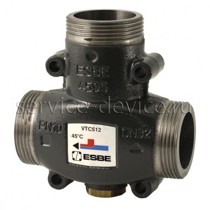
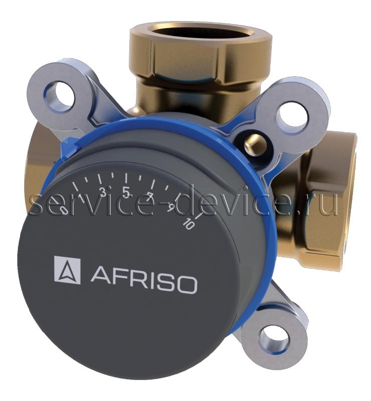
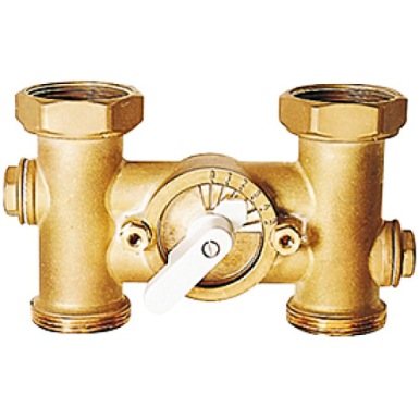
Like its more "modest" three-way counterpart, the four-way valve is made of high-quality brass, but instead of three connecting pipes it has as many as 4. A spindle with a cylindrical working part of a complex configuration rotates inside the body on a sealing sleeve.
In it, on two opposite sides, samples are made in the form of bald spots, so that in the middle the working part resembles a damper. It retains a cylindrical shape at the top and bottom so that a seal can be made.
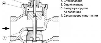
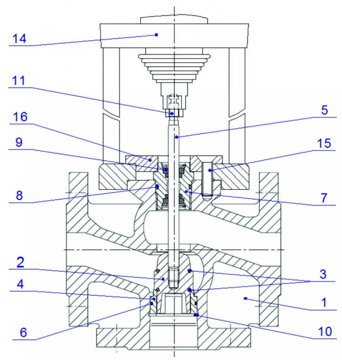
The spindle with the sleeve is pressed against the body by a cover on 4 screws, an adjusting handle is pushed onto the shaft end from the outside, or a servo drive is installed. What this whole mechanism looks like, the detailed diagram of a four-way valve shown below will help to give a good idea:
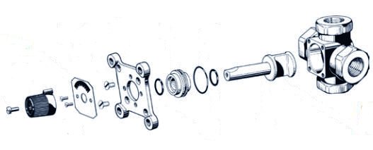
The spindle rotates freely in the sleeve because it has no thread. But at the same time, the samples made in the working section can open the duct through two passes in pairs or allow three streams to mix in different proportions. How this happens is shown in the diagram:
For reference. There is another design of the four-way valve, where a push rod is used instead of a rotating spindle. But such elements cannot mix flows, but only redistribute. They have found their application in gas double-circuit boilers, switching the flow of hot water from the heating system to the DHW network.
The peculiarity of our functional element is that the coolant flow supplied to one of its nozzles can never pass to the other outlet in a straight line. The flow will always turn into the right or left branch pipe, but will never get into the opposite one. At a certain position of the spindle, the damper allows the coolant to pass immediately to the right and left, mixing with the flow coming from the opposite inlet. This is the principle of operation of a four-way valve in a heating system.
It should be noted that the valve can be controlled in two ways:
manually: the required flow distribution is achieved by installing the stem in a certain position, guided by the scale opposite the handle. The method is rarely used, since the effective operation of the system requires periodic adjustments, it is impossible to constantly perform it manually;
automatic: the valve spindle is rotated by a servo motor, which receives commands from external sensors or the controller. This allows you to adhere to the set water temperatures in the system when the external conditions change.

THREE-WAY CONTROL VALVES TRV-3
Description, scope
Three-way mixing control valves are used as actuators in heating, cooling, air conditioning systems, as well as technological processes in which remote control of the flow of liquids is required.
The valve is controlled by an electric actuator (electric drive). The force developed by the electric drive is transmitted to the plunger, which moves up and down, changing the flow area in the valve and regulating the flow rate of the working medium.
NOMENCLATURE
TRV-3-X1-X2-X3 Where: TRV-3 - Designation of a three-way mixing control valve X 1 - Nominal diameter DN (select from table 2.4) X 2 - Conditional throughput Kvs (select from table 2.4) X 3 - Drive type marking from 1 to 8 and from 17 to 24 and from 29 to 30 (select from table 2.2)
EXAMPLE OF ORDER: Three-way mixing control flanged valve with a nominal diameter of 15 mm, with a capacity of 2.5 m3 / h, a maximum temperature of the working medium of 150 ° C and equipped with a Regada ST mini 472.0-OTFAG / 00 actuator without a position sensor (actuator type 2). TRV-3-15-2.5-2
SPECIFICATIONS
Table 2.4
| NAME OF PARAMETERS, units | VALUE OF PARAMETERS | ||||||||
| Nominal diameter, DN, mm | 15 | 20 | 25 | 32 | 40 | 50 | 65 | 80 | 100 |
| Conditional throughput, Kvs m3 / h | 0,63 1,25 1,6 2,5 4 | 5 6,3 | 8 10 | 12,5 16 | 20 25 | 31,5 40 | 50 63 | 80 100 | 125 160 |
| Throughput characteristic | A - AB, equal percentage; B - AB, linear | ||||||||
| Nominal pressure PN, bar (MPa) | 16 (1,6) | ||||||||
| Workspace | Water with temperatures up to 150 ° С, 30% aqueous solution of ethylene glycol | ||||||||
| Rod stroke, mm | 14 | 30/25* | |||||||
| Connection type | flanged | ||||||||
| Materials: - valve body - shutoff assembly (plunger) - stem and seat of channel B - unloading chamber seals - stem seal | Cast iron Brass CW614N Corrosion-resistant steel GOST 5632 Heat-resistant EPDM rubber EPDM rubber gaskets, guides - PTFE | ||||||||
* Only for actuated valves with position transmitter with 4-20mA current signal
THE DESCRIPTION AND DIAGRAMS OF ACTUATORS INCLUDED IN SECTION 1.1
REGULATION CHARACTERISTICS | VALVE DEVICE |
| Valve device with ST mini actuator |
MOUNTING POSITIONS |
|
| Valve device with REGADA ST 0 actuator; STR 0PA; STR 0.1PA | |
| |
| Mounting positions for valve with REGADA actuator (Straight sections before and after the valve are not required) |
DIMENSIONS
| Name of parameters, units | Parameter values | ||||||||
| Nominal diameter DN, mm | 15 | 20 | 25 | 32 | 40 | 50 | 65 | 80 | 100 |
| Length L, mm | 130 | 150 | 160 | 180 | 200 | 230 | 290 | 310 | 350 |
| Height, Н1, mm | 65 | 70 | 75 | 95 | 100 | 100 | 120 | 130 | 150 |
| Valve height H: | |||||||||
| with TSL-1600 drive | 402 | 407 | 417 | 427 | 437 | 442 | |||
| - with drive type ST mini 472.0, mm / no more | 400 | 405 | 415 | 423 | 435 | 445 | |||
| - with drive type ST 0 490.0, mm / no more | 535 | 555 | 575 | 595 | 625 | ||||
| - with drive type AVF 234S F132, mm / no more | 402 | 410 | 420 | 428 | 440 | 450 | 525 | 545 | 575 |
| Valve weight: | |||||||||
| with TSL-1600 drive | 6,3 | 7,2 | 8,2 | 10,8 | 12,3 | 14,8 | |||
| -with drive type ST mini 472.0, kg / no more | 6,1 | 7 | 8 | 10,6 | 12,1 | 14,6 | |||
| -with drive type ST 0 490.0, kg / no more | 14,2 | 16,2 | 25 | 33 | 40 | ||||
| - with drive type AVF 234S F132, kg / no more | 10,1 | 11,2 | 12,2 | 14,8 | 16,3 | 18,8 | 28 | 32 | 37,5 |
EXAMPLE OF SELECTION
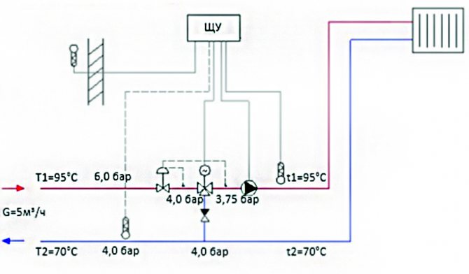
An electrically actuated three-way mixing control valve is required to control the temperature in the heating circuit. Network heat carrier consumption: 5 m³ / h. Pressure upstream of 3-way mixing control valve as per circuit requirement (port A and port B): 4 bar. In the circuit solution, there is an equality of the temperature graphs of the network circuit and the circuit of the heat consumption system - for this reason, a three-way mixing control valve with an electric drive was chosen.
According to the recommendations for the selection of control valves:
|
| When choosing a circulation pump, it is necessary to additionally take into account the differential pressure across the three-way valve to determine the required pump head. |
- Using the formula (4), we determine the minimum nominal valve diameter: (4) DN = 18.8 *√(G/V)
= 18,8*
√(5/3) = 24.3 mm. The speed in the outlet section V of the valve is chosen equal to the maximum allowable (3 m / s) for valves in the ITP in accordance with recommendations for the selection of control valves and pressure regulators of direct action of the Teplosila Group of Companies in the ITP / Central Heating Station.
2. Using the formula (1), we determine the required throughput of the valve:
(1)Kv = G /√ΔP
= 5/
√0.25 = 10.0 m3 / h. The pressure drop across the valve ΔP is chosen equal to the pressure drop in the heating circuit in accordance with recommendations for the selection of control valves and pressure regulators of direct action of the Teplosila Group of Companies in the ITP / Central Heating Station.
3. Select a two-way valve (Type TRV-3) with the nearest large nominal diameter and the nearest smaller (or equal) nominal capacity Kvs: DN = 25 mm, Kvs = 10 m3 / h. 4. Using the formula (2), we determine the actual differential across the fully open valve at a maximum flow rate of 5 m3 / h:
(2) ΔPf = (G / Kvs) 2
= (5/10) 2 = 0.25 bar. 5. The pressure downstream of the 3-way control valve at a set flow rate of 5 m3 / h and an actual differential of 0.25 bar will be 4.0 - 0.25 = 3.75 bar. 6. From table 1.2 we select the TSL-1600 drive from Zavod Teplosila LLC (drive type 101). 7. Nomenclature for order:
TRV-3-25-10-101.
Practical use
Wherever it is necessary to ensure high-quality regulation of the coolant, four-way valves can be used. Quality control is the control of the temperature of the coolant, not its flow rate. There is only one way to achieve the required temperature in the water heating system - by mixing hot and cooled water, obtaining a coolant with the required parameters at the outlet. The successful implementation of this process is precisely what ensures the device of the four-way valve. Here are a couple of examples of setting an element for such cases:
- in a radiator heating system with a solid fuel boiler as a heat source;
- in the underfloor heating circuit.
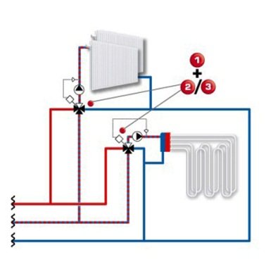
As you know, a solid fuel boiler in the heating mode needs protection from condensation, from which the walls of the furnace are subject to corrosion. The traditional arrangement with a bypass and a three-way mixing valve that prevents cold water from the system from entering the boiler tank can be improved. Instead of a bypass line and a mixing unit, a four-way valve is installed, as shown in the diagram:

A natural question arises: what is the use of such a scheme, where you have to install a second pump, and even a controller to control the servo drive? The fact is that here the operation of the four-way valve replaces not only the bypass, but also the hydraulic separator (hydraulic arrow), if there is a need for one. As a result, we get 2 separate circuits that exchange coolant with each other as needed. The boiler receives chilled water in a metered dose, and the radiators receive the heat carrier with the optimal temperature.
Since the water circulating through the heating circuits of the underfloor heating heats up to a maximum of 45 ° C, it is unacceptable to run the coolant in them directly from the boiler. In order to withstand this temperature, a mixing unit with a three-way thermostatic valve and a bypass is usually installed in front of the distribution manifold. But if, instead of this unit, a four-way mixing valve is installed, then return water from the radiators can be used in the heating circuits, as shown in the diagram:
Calculation of the Kvs value of a three-way valve and a circulation pump
Kvs of the valve - characteristic of the throughput of the valve; nominal volumetric flow rate of water through a fully open valve, m3 / h at a pressure drop of 1 bar under normal conditions. The indicated value is the main characteristic of the valve.
To calculate the Kvs, the pressure drop across the valve versus Kvs and volumetric flow can be used.
You can choose a circulation pump at this link.
| Designation | Unit | Description |
| Kv | m3 / h | Consumption coefficient in constituent units of consumption |
| Kv100 | m3 / h | Discharge coefficient at nominal displacement |
| Kvmin | m3 / h | Consumption coefficient at minimum consumption rate |
| Kvs | m3 / h | Conditional coefficient of consumption of reinforcement |
| Q | m3 / h | Volume flow in operation (T1, p1) |
| Qn | Nm3 / h | Volume flow in normal state (0 ° C, 0.101 MPa) |
| p1 | MPa | Absolute pressure in front of the control valve |
| p2 | MPa | Absolute pressure control valve |
| ps | MPa | The absolute pressure of saturated steam at a given temperature (T) |
| Δp | MPa | Differential pressure across the control valve (Δp = p1 - p2) |
| ρ1 | kg / m3 | Density of the working medium in operation (T1, p1) |
| ρn | kg / Nm3 | Density of gas in normal state (0 C, 0.101 MPa) |
| T1 | TO | Absolute temperature before valve (T1 = 273 + t) |
| r | 1 | Regulatory attitude |
Calculation of the Kv coefficient
The main flow characteristic of control valves is the conditional flow coefficient Kvs... Its value indicates the characteristic flow through a given valve under well-defined conditions at 100% opening. To select control valves with one or another Kvs value, it is necessary to calculate the flow coefficient Kv, which determines the volumetric flow rate of water in m3 / h that will flow through the control valve under certain conditions (pressure loss on it is 1 bar, water temperature 15 ° C, turbulent flow, sufficient static pressure to exclude cavitation under these conditions).
The table below shows the calculation formulas Kv for different environments
| Loss of pressure p2> p1 / 2 Δp | Loss of pressure p2 ≥ p1 / 2 Δp ≤ p1 / 2 | ||
| Kv = | Liquid | Q / 100 x √ ρ1 / Δp | |
| Gas | Q / 5141 x √ ρ1 * T1 / Δp * p2 | 2 * Qn / 5141 * p1 x √ ρn * T1 | |
The advantage of this coefficient is its simple physical interpretation and the fact that in cases where the working medium is water, it is possible to simplify the calculation of the flow rate in direct proportion to the square root of the pressure drop. Having reached the density of 1000 kg / m3 and setting the pressure drop in bars, we get the simplest and most famous formula for calculating Kv:
Kv = Q / √ Δp
In practice, the calculation of the flow coefficient is carried out taking into account the state of the control circuit and the working conditions of the material according to the above formulas. The control valve must be sized so that it is able to regulate the maximum flow rate under the given operating conditions. In this case, it should be ensured that the smallest regulated flow is also amenable to regulation.
Provided that the regulating ratio of the valve is: r> Kvs / Kvmin
Due to a possible minus 10% tolerance of the Kv100 value in relation to Kvs and the requirement for the possibility of regulation in the area of the maximum flow rate (flow reduction and increase), it is recommended to select a Kvs value of the control valve that is higher than the maximum operating Kv value:
Kvs = 1.1 ÷ 1.3 Kv
In this case, it is necessary to take into account the content of the “safety margin” in the calculation of the assumed value of Qmax, which may cause an overestimation of the valve performance.
Simplified calculation process for 3-way mixing valve
Initial data: medium - water 90 ° C, static pressure at the point of connection 600 kPa (6 bar),
Δppump 02 = 35 kPa (0.35 bar), Δppipe = 10 kPa (0.1 bar), Δpheat exchange = 20 kPa (0.2 bar),
nominal flow rate Qnom = 5 m3 / h.
A typical layout of a control loop using a 3-way mixing valve is shown in the figure below.
Δppump 02 = Δpvalve + Δpheat exchange + Δppipe
Δpvalve = Δppump 02 - Δpheat exchange - Δppipe = 35 - 20 - 10 = 5 kPa (0.05 bar)
Kv = Qnom / √∆p valve = 5 / √0.05 = 22.4 m3 / h
Safety allowance (provided that the flow rate Q was not overstated):
Kvs = (1.1 ÷ 1.3) * Kv = (1.1 ÷ 1.3) * 22.4 = 24.6 ÷ 29.1 m3 / h
From the serially produced series of Kv values, we select the closest Kvs value, i.e. Kvs = 25 m3 / h. This value corresponds to a control valve with a diameter of DN 40.
Determination of hydraulic losses at the selected valve at full opening and a given flow rate
Δpvalve H100 = (Qnom / Kvs) 2 = (5/25) 2 = 4 kPa (0.04 bar)
Warning: For three-way valves, the most important condition for correct operation is the observance of the minimum pressure difference between ports A and B. Three-way valves are able to cope with significant differential pressures between ports A and B, but due to deformation of the control characteristic, the control ability is deteriorated. Therefore, if there is the slightest doubt about the pressure difference between both nozzles (for example, if the three-way valve is directly connected to the mains), we recommend using a two-way valve for quality control.
Determining the authority of the selected valve
The authority of the direct branch of a three-way valve in such a connection, provided that the flow rate along the consumer's circuit is constant
a = Δp valve Н100 / Δp valve Н0 = 4/4 = 1
Indicates that the flow relationship in the straight leg of the valve corresponds to the ideal flow curve of the valve. In this case, the Kvs of both branches coincide, both characteristics are linear, which means that the total flow rate is almost constant.
The combination of equal percentage characteristic on path A, with a linear characteristic on path B, is sometimes advantageous to choose in cases where it is impossible to avoid loading of bushings A with respect to B with differential pressure, or if the parameters on the primary side are too high.