Valves are integral elements of any heating system (CO), regardless of the chosen scheme and configuration of the circuits. With the help of these simple devices, the heat supply parameters are adjusted, ensuring the safety and stability of the system. This publication will consider the main valves used in centralized and autonomous heating systems, their purpose, principle of operation and design features.
[contents]
Criterias of choice
The number and parameters of valves required for a specific CO is selected at the stage of calculations and design. The main criteria that affect the choice of these elements are:
- Type, scheme and configuration of CO.
- Temperature conditions (nominal and maximum).
- System pressure (working and maximum).
- Pipeline section and thread type.
- Coolant type (water, brines, antifreezes).
The operation of these devices stabilizes CO, makes it efficient and safe. Anyone who is engaged in self-installation of a heating system in a home needs to know the purpose and their principle of operation. All valves can be divided according to their purpose into three categories: safety, control and regulation group.
Everyone knows that any CO is an increased source of danger, since the coolant in the system is under pressure. And the higher the temperature, the higher the pressure (in closed CO). Next, consider the devices that are responsible for the safety of the CO
Output
The use of shut-off and control valves enables the automation to control the set comfort parameters without your intervention. It also allows you to quickly intervene in the system in the event of an emergency or repair work. Installation of devices is not difficult and is done independently. The video in the article will provide an opportunity to find additional information on the above topic.
Did you like the article? Subscribe to our channel Yandex.Zen
Safety
In most models of modern boilers, manufacturers provide a safety system, the "key figure" of which is the safety fittings included directly in the boiler heat exchanger or in its piping.
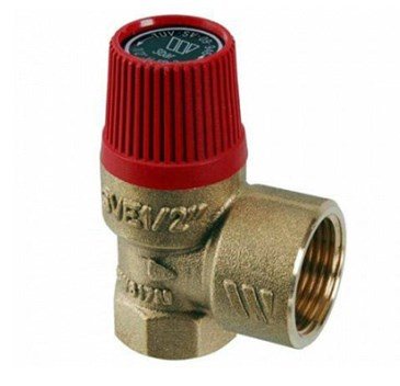
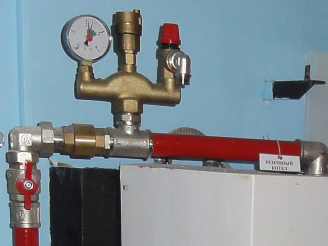
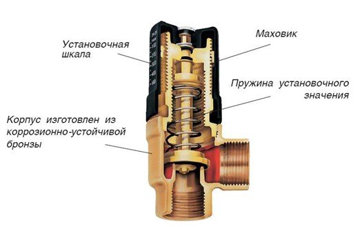
Appointment safety valve in the heating system consists in preventing the pressure rise in the system above the permissible level, which can lead to: destruction of pipes and their connections; leaks; explosion of boiler equipment
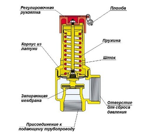
The design of this kind of fittings is simple and unpretentious. The device consists of a brass body, which houses a spring-loaded closing diaphragm connected to a stem. Spring resilience is the main factor that keeps the diaphragm in the locked position. The adjusting handle adjusts the compression force of the spring.
When the pressure on the diaphragm is higher than the set one, the spring is compressed, it opens and the pressure is released through the side hole. When the pressure in the system cannot overcome the elasticity of the spring, the diaphragm will return to its original position.
Tip: Purchase a safety device with pressure regulation from 1.5 to 3.5 bar. Most models of solid fuel boiler equipment fall into this range.
Air vent
Quite often, air locks form in CO. As a rule, there are several reasons for their appearance:
- boiling of the coolant;
- high air content in the coolant, which is automatically added directly from the water supply;
- As a result of air leaks through leaking connections.
The result of air locks is uneven heating of radiators and oxidation of the inner surfaces of the CO metal elements. The air relief valve from the heating system is designed to evacuate air from the system in automatic mode.
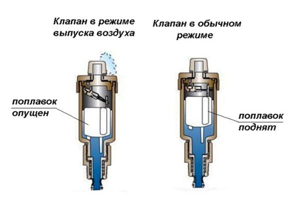
Structurally, the air vent is a hollow cylinder made of non-ferrous metal, in which a float is located, connected by a lever with a needle valve, which in the open position connects the air vent chamber to the atmosphere.
In working condition, the inner chamber of the device is filled with a coolant, the float is raised, and the needle valve is closed. If air enters, which rises to the upper point of the device, the coolant cannot rise in the chamber to the nominal level, and therefore, the float is lowered, the device operates in the exhaust mode. After the air is released, the coolant rises in the chamber of this kind of fittings to the nominal level, and the float takes its regular place.
Valve installation location
There are points in the heating system where air is necessarily collected. So, Mayevsky's taps in the apartment should be installed on each radiator. In many modern radiator models, air bleed devices are installed at the manufacturing stage by the manufacturers themselves.
We recommend that you familiarize yourself with: The use of plastic pipes for the organization of drainage systems
Note! If you have classic radiators, then the air valve should be installed in the upper part of it, which is located opposite the connection.
So you can always independently control the normal operation of your heating batteries and not depend on the desire of the housing office employees or the mood of the neighbors from above.
Points for installing air relief valves:
- radiators, bathroom coil, upper part;
- the top point of the pipeline;
- heating boiler safety system in individual communications;
- for hydraulic branching;
- on the collectors of the common manifold;
- on any U-shaped loops in communications, at the top point;
- for expansion joints in plastic heating systems.
It should be understood that air always accumulates in the upper part of the communications. An air lock can arise in the bend of a plastic pipe if the installation was carried out incorrectly and there was a temperature deformation.
The easiest way to get rid of the plug in the pipeline permanently is to cut a tee into the pipe. On the free vertical branch of the tee (the diameter of which is selected accordingly), a valve is installed to release air.
Back
In gravity CO, there are conditions under which the coolant can change the direction of movement. This threatens to damage the heat exchanger of the heat generator due to overheating. The same can happen in sufficiently complex COs with forced movement of the coolant, when water, through the bypass pipe of the pumping unit, enters the boiler back into the boiler. Mechanism of action check valve in the heating system quite simple: it passes the coolant only in one direction, blocking it when moving back.
There are several types of this kind of fittings, which are classified according to the design of the locking device:
- disc-shaped;
- ball;
- petal;
- bivalve.
As it is already clear from the name, in the first type, a steel spring-loaded disk (plate), connected to the stem, acts as a locking device. In a ball valve, a plastic ball acts as a shutter. Moving "in the right" direction, the coolant pushes the ball through the channel in the body or under the cover of the device.As soon as the circulation of water stops or the direction of its movement changes, the ball, under the influence of gravity, takes its original position and blocks the movement of the coolant.
In the petal, the locking device is a spring-loaded cover, which is lowered when the direction of water in CO changes under the action of natural gravity. The bivalve element is installed (as a rule) on large diameter pipes. The principle of their work does not differ from the petal one. Structurally, in such an armature, instead of one petal, spring-loaded from above, two spring-loaded flaps are installed.
These devices are designed to regulate temperature, pressure, and stabilize the work of CO.
Installation of a non-return valve for heating
Most often, back pressure shut-off devices are used in boiler piping schemes. They are especially relevant when you need to connect several heat generators in a cascade or synchronize the operation of boilers on different energy sources. Then the valve does not allow parasitic flows of the coolant to arise, which will surely occur when heat sources are connected in parallel.
When the water supply in the heating system is carried out by a circulation pump, then any of the listed types of valves can be used. In gravity systems, only gravity valves can be used. In this case, the following rules must be observed:
- select a product according to the operating pressure and temperature of the coolant. As a rule, in the pipelines of private houses, the pressure is within 3 bar, and the temperature is 95 ºС. If the building is connected to a centralized network, then you need to find out its parameters and select a product based on them;
- it should be remembered that in the heating system, the check valve is installed in the position indicated in the technical passport. As a rule, all spring-loaded devices function successfully in both horizontal and vertical positions. And only the gravitational shutter is always placed horizontally;
- when installing the device in the boiler circuit on the return pipe, do not forget that it must be located after the circulation pump, and not before it.
Note. The type of connection of the product depends on the operating pressure in the network. If it is less than 16 Bar, then coupling valves are installed, and when it is higher, then flanged (or inter-flanged) valves are installed.
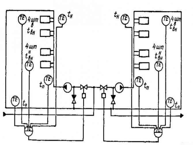
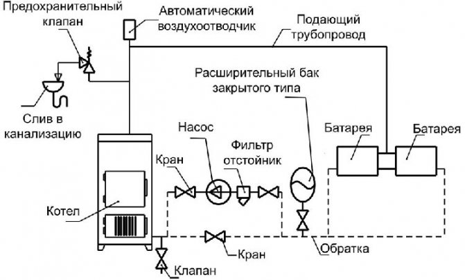
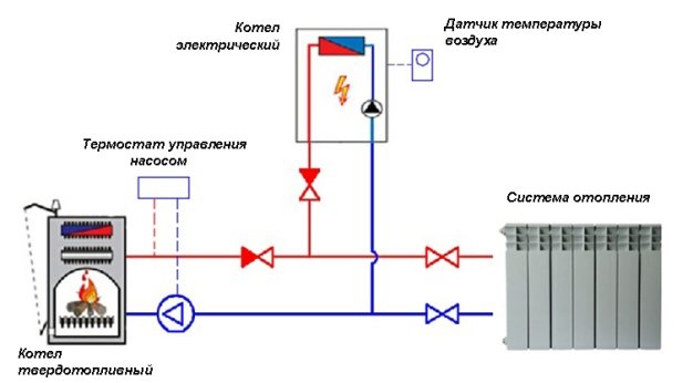
Below, as an example, a diagram is shown for connecting two boilers - solid fuel and electric using check valves to prevent parasitic flows:
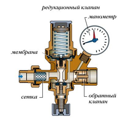
Balancing
Any CO requires hydraulic adjustment, in other words - balancing. It is carried out in various ways: by correctly selected pipe diameters, washers, with different flow cross-sections, etc. balancing valve for heating system.
The purpose of this device is that the required volume of coolant and the amount of heat can be supplied to each branch, circuit and radiator.
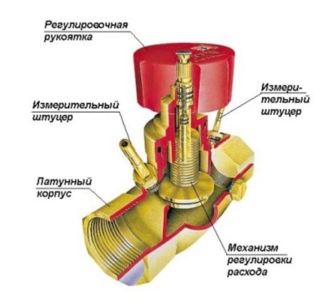
The valve is a conventional valve, but with two fittings installed in its brass body, which make it possible to connect measuring equipment (manometers) or a capillary tube with an automatic pressure regulator.
The principle of operation of the balancing valve for the heating system is as follows: By turning the adjusting knob, it is necessary to achieve a strictly defined flow rate of the coolant. This is done by measuring the pressure at each nozzle, after which, according to the diagram (usually supplied by the manufacturer to the device), the number of turns of the adjusting knob is determined to achieve the desired water flow rate for each CO circuit.Manual balancing regulators are installed on circuits with up to 5 radiators. On branches with a large number of heating devices - automatic.
Bypass
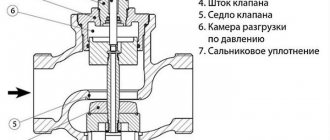
This is another CO element designed to equalize the pressure in the system. Principle of operation bypass valve of the heating system is similar to the safety one, but there is one difference: if the safety element bleeds off excess coolant from the system, then the bypass returns it to the return line past the heating circuit.
The design of this device is also identical to the safety elements: a spring with adjustable elasticity, a shut-off diaphragm with a stem in a bronze casing. The flywheel adjusts the pressure at which this device is triggered, the membrane opens the passage for the coolant. When the pressure in CO stabilizes, the membrane returns to its original place.
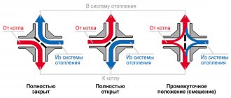
Three-way
There is a practice to achieve a certain temperature of the coolant in various branches and circuits of the CO by mixing or dividing the coolant flows. Three-way valve on the heating system plays the role of a device that regulates the temperature of the working fluid after the heat generator.
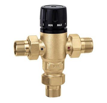
The design of the mixing valve is simple: there are three openings in the body of the device, two inlets and one outlet. Isolating devices have one input and two outputs.
The main control device of this element is a thermal head, inside which there is a reservoir with a liquid (bellows). When the remote sensor is heated, the liquid in it expands and enters the bellows. The volume of this reservoir expands and acts on the valve stem, which opens or closes the mixing or splitting ports. The separating types of this CO element use the same principle, but the stem does not open the passage for flows, but divides one flow into two.
The device can be controlled not only by the thermostatic head. Manual devices are quite popular. The depth of pushing the rod is determined by the rotation of the control handle. Today, on the market of climatic technology, these devices with electric and servo drives are widely represented.
Automatic make-up device
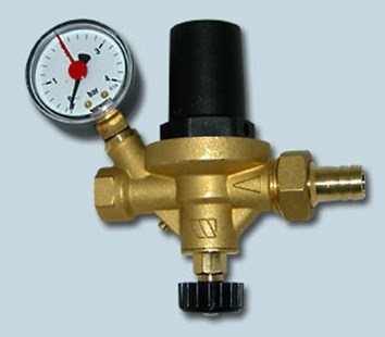
Due to various circumstances (natural evaporation, operation of the safety element, etc.), the volume of the coolant in CO may decrease. The less coolant, the more air in the system, which inevitably disrupts the circulation of water in CO and overheating of boiler equipment. To prevent air from entering the system, it is necessary to replenish the amount of coolant in time. You can do this manually, or you can install heating system make-up valve, thereby to organize automatic replenishment of CO with a coolant.
The design of this kind of fittings practically does not differ from safety fittings, but the principle of operation is exactly the opposite: as long as there is the necessary pressure in the CO, which supports the diaphragm against the seat, the spring is in a compressed state. When the pressure drops below the minimum, the spring straightens and pushes the membrane away from the seat, allowing water from the supply tank or water supply network to enter the CO. In fig. The construction of this device is shown below.
As CO is filled, the pressure in it increases, the spring is compressed, and the membrane sits in the seat on the body, shutting off the make-up.
Important! Valve selection is a complex and important process that is best left to professionals.
Benefits of using manual valves
- Saving... Adjusting the flow of the coolant allows you to control the consumption of thermal energy, depending on the season, the air temperature in the room;
- Comfort... Different rooms in the same private house do not require the same heating. In the kitchen, utility areas, the temperature should be lower than in children's rooms or bathrooms.The thermal regime of the dwelling can be effectively changed depending on the time of day (warmer during the day);
- Extending the service life of the heating system... The principle of operation of the manual valve assumes smooth adjustment (which cannot be ensured, for example, with ball valves, where the water flow is blocked or opened almost instantly, and the radiator is subjected to mini-water shocks at the same time).
- Versatility of use in various systems... The regulating manual valve can be used in drinking, household, heating systems. Installation in process pipelines is possible, provided that raw materials and liquids are transported that are not aggressive to the body material.
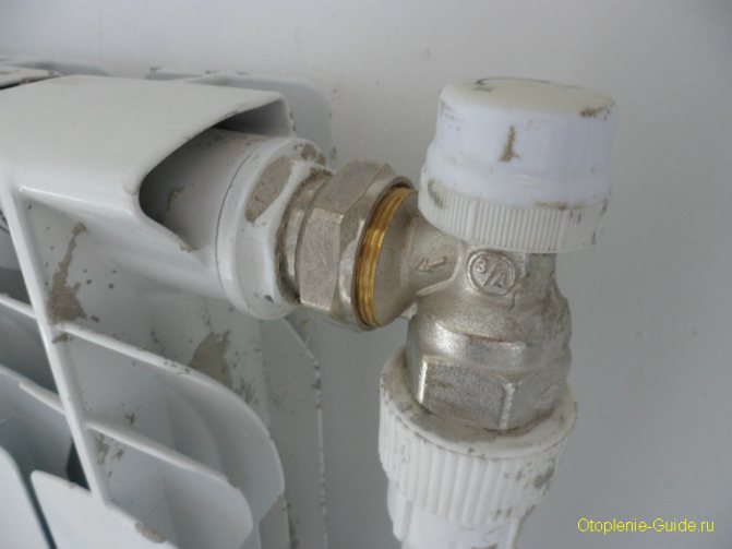
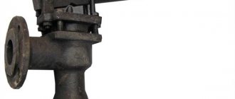
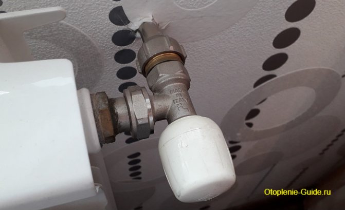
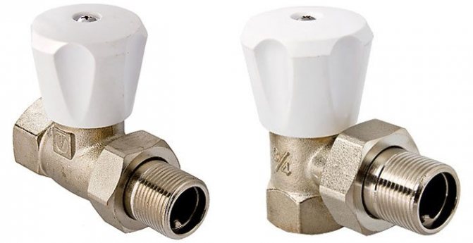
Angle radiator valve.