Home ›Engineering systems› Integrated solutions ›Ventilation and heating› Installation of heating and ventilation
You can order the installation of heating and ventilation systems on a turnkey basis with installation by calling in Moscow. Design and supply of heating and ventilation systems in Russia. We ask you to send a written application by email or through the form on the website.
- What is SNiP?
- Heating system installation sequence technology
- Installation of basic types of heating
- Ventilation system assembly sequence technology
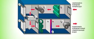
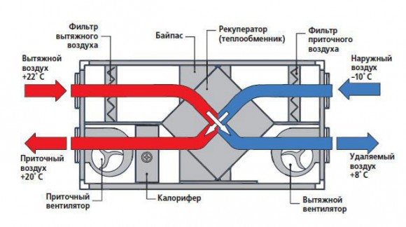
- Ventilation and heating by means of a recuperator
Send an application and get a quote
- Rates
for the installation of engineering systems
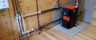
The installation of a modern heating and ventilation system implies the presence of special devices for connecting pipes (a soldering iron for plastic - for a plastic heat conductor). When you purchase, you are supplied with a disassembled system, and in addition to pipes, it contains corners, tees, couplings, plugs. You can put it all together with a plan or project drawn up by experts. The parts required to connect the elements of the system are called couplings. They are often in short supply, so it is worth stocking up on them.
"Standard Climate" is a professional climatic company, ready to implement solutions to any problems in climatic and other engineering equipment on a turnkey basis. We will perform a full cycle of work: selection of equipment, design, installation, delivery and maintenance. On the website airclimat.ru you can send an application. Call now: +7(499) 350-94-14
... Submit your application
What is SNiP?
The rules for the design and installation of heat supply, ventilation, and air conditioning systems are described in detail in SNiP, which is a set of regulatory documents for construction. In addition to building codes and regulations, SNiP also describes sanitary, fire safety and environmental measures that should be observed when operating such systems.
Of course, in addition to SNiP, heating, ventilation and air conditioning, there is also a whole list of SNiPs, SanPiNs, GOSTs, as well as other documents that describe the requirements for observing the required dimensions, tolerances, safety measures, and some hygienic conditions. When drafting a particular system, it is very important to comply with the norms and rules given in the documents. Therefore, you should familiarize yourself with SNiP in more detail. There are various SNiPs, which disclose important rules for the design and installation of heating, air conditioning and ventilation systems.
For example, there are such versions of documents:
- 2.04 05 91 heating, ventilation and air conditioning: contains the fire safety requirements for these systems.
- 41-01-2003: describes sanitary, environmental, fire safety standards for heat supply systems. This is a newer version.
Observing the joint venture heating, ventilation and air conditioning during project development and installation work, you can be sure of the quality and reliability of the equipped system. But it is not enough to correctly design the system. It is also important to use it correctly. For these purposes, an instruction manual for the heating and ventilation system has been developed, which establishes a number of requirements for the use of the heating network, tests, start-ups, as well as adjustments to the structure.
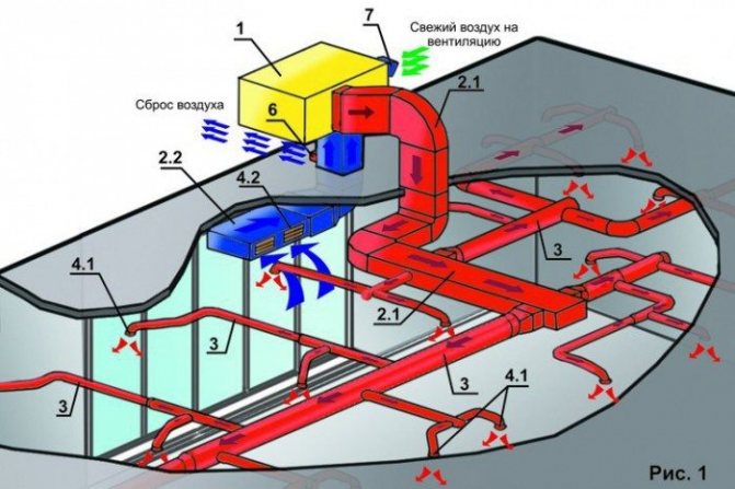
Simple calculation of an air heating system combined with supply ventilation
Here, of course, much depends on the way the air circulation is organized. If, for example, only partial recirculation is used, then this will allow you to save a little on electricity, because the heating device does not have to waste energy on heating air with a temperature equal to the outside temperature.
On the other hand, the option with partial recirculation is not always acceptable from a purely hygienic point of view, because some of the polluted air will still remain in the room. But zero recirculation, especially in the cold season, will cost the owners a lot, but the air will be guaranteed to be clean.
The calculation of air heating combined with ventilation is based on the fact that the set air temperature must be maintained in the room. The inflow should not suffer from this, that is, the frequency of replacing the air in the room should also be constant.
The air supply should be approximately equal to the exhaust
A very simplified version of the calculation is given as a sample, but it is suitable, for example, for private construction.
The whole calculation can be divided into 3 simple steps:
- It is necessary to determine the heat loss in the room. To simplify the calculation, it is advisable to use an online calculator, this will take into account the subtleties like the type of glass unit installed in the apartment, the climatic zone, etc. When calculating manually, many beginners have difficulties with this;
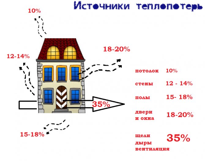
The main sources of heat loss
Note! The ability of the heater to maintain the desired temperature in the apartment will depend on the correctness of this point. If, for example, the result turns out to be underestimated, then the heater simply will not cope and you can forget about comfort.
- Then you need to set the temperature that must be maintained in the room and the outlet temperature (at the outlet from the heater) and determine the air flow under the given conditions. The calculation is carried out according to the formula
G = Qп / [s ∙ (tg-tv)],
in this formula, the following designations are adopted:
- Qп - heat loss, calculated at the previous stage, W;
- с - heat capacity of air, J / (kg ∙ K), reference value, is taken equal to 1005;
- tg and tв - temperature from the heater and temperature in the room, ᵒС.
- The heat consumption that will have to be spent on heating this air is determined, the formula is used
Qн = G ∙ c ∙ (tv-tн),
where tн is the outside air temperature, ᵒС.
Calculation example
As an example, let's perform a simple calculation in which the task is to calculate heating and ventilation, provided they work together.
The following initial data are accepted:
- the room has double-glazed windows, and the glazing area in percentage is 20% of the wall area;
- an external temperature of -30ᵒС is accepted;
- in the room only one wall goes out;
- room area - 20 m2;
- the house must constantly maintain the temperature at +20 ᵒС, the supply temperature is +50 ᵒС;
The calculation is performed according to the recommended method:
- heat loss for such a case will be 2.26 kW;
- air consumption for such a case should be G = 2260 / (1005 (50-20)) = 0.075 kg / s;
- heat for heating will need Qн = 0.075 ∙ 1005 ∙ (20 - (- 30)) = 3769 W = 3.77 kW. Already relying on these data, you can select a heating device according to passport characteristics.
Heating system installation sequence technology
When installing heating systems, it must be ensured:
accurate performance of work in accordance with the project and the instructions of SNiP; density of connections, strength of fasteners of system elements; verticality of risers; compliance with the slopes of the distribution and main sections; absence of curvature and kinks in straight sections of pipelines; serviceable operation of shut-off and control valves, safety devices and instrumentation; the possibility of removing air, emptying the system and filling it with water; reliable fastening of equipment and guards of their rotating parts.
When installing CO, the following sequence of work is applied:
- unloading, picking, delivery of pipe and heating units to the place of installation;
- installation of trunk pipelines;
- installation of heating devices;
- installation of risers and connections;
- system testing.
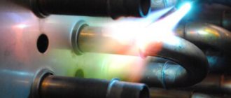
The installation of main pipelines is carried out after the layout of the mounting assemblies on the supports and hanging them to the building structures by assembling the assemblies on flax and red lead or joining the assemblies with their subsequent welding. Then the lines are verified and fixed on supports and hangers.
After assembling the main pipelines, risers and branches are connected to them to the equipment. First, the heating units are installed in place and verified by level and plumb line, then the heating units are connected using an interfloor insert. Heaters are connected to the interfloor inserts by means of a thread or by welding.
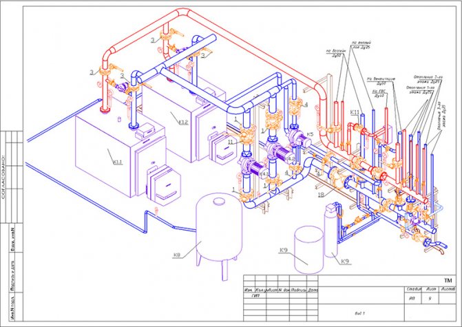
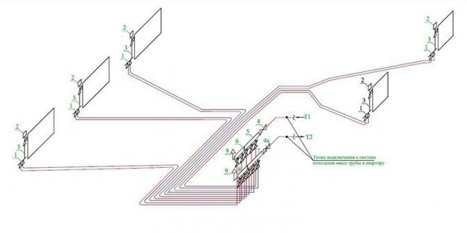
Heating axonometry: what to look for?
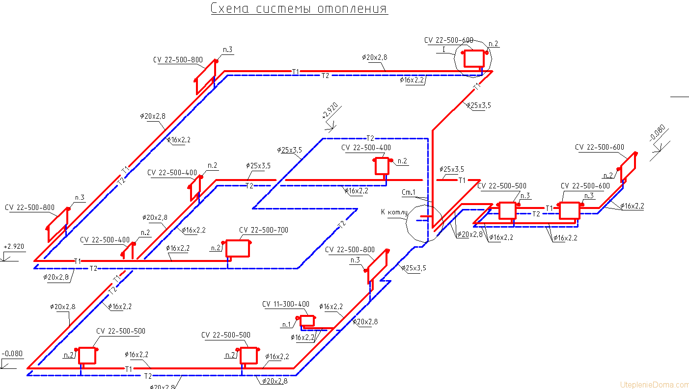
Heating axonometry.
The implementation of a heating project for a residential building, administrative building or industrial facility involves drawing an axonometric diagram of the heating system. Before displaying the system on paper or in a computer program, it is necessary to carry out calculations. The scheme itself is drawn up on the basis of the following data:
- the value of the heat demand for each room in the building;
- type of heating devices, their number for each room;
- basic solutions for the entire engineering network, including the use of risers in the system, calculation of hydraulic branches and circuits, the procedure for connecting heating devices;
- characteristics of pipeline sections, namely: diameter, length of each pipe fragment, shut-off valves, thermal controllers, hydraulic regulators (in situations where pressure controllers are not pre-installed in the boiler unit).
After performing the appropriate calculations, the obtained values are transferred to the drawing. The axonometric diagram of the heating system contains the characteristics of the equipment (boilers, pumps), the length and diameter of the pipelines, as well as the flow rate, and the thermal properties of heating devices (radiators, convectors, registers). When drawing an axonometry, it is necessary to determine the main ring of movement of the coolant. This is the path to the farthest element from the boiler and back.
One of the most convenient and quickest heating methods is heating the garage with an electric diode boiler.
Here you can read about heating a garage with used oil using a pyrolysis oven.
Installation of basic types of heating
- Heating by heating water. The main element here is the water heater, but during installation, more attention is paid to the water pipes. They can be anything from iron to thin plastic.
- Heating with hot steam. For this type, it is necessary to install a steam generator and system channels through which hot steam will flow. These can be steel pipes with radiators, which will be selected when designing the system.
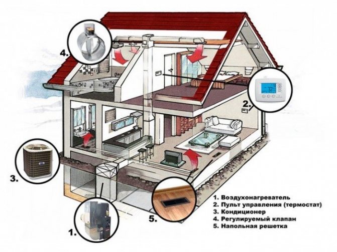
- Heating with air heating. Acts on the principle of conditioning. The air entering the apartment passes through the heater.
- Electric heating. The installation of these systems is rather complicated; they are more expensive to work with than others.
Two-pipe system
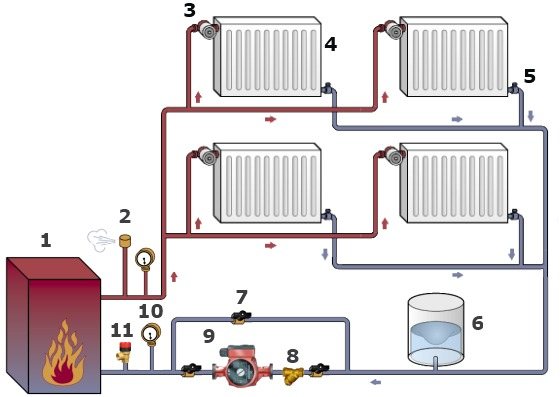
The composition of such a heating system includes supply and discharge pipes. The coolant flows through the supply pipe to the radiators connected in parallel. Through the outlet (return), the liquid that has given off heat returns back to the boiler. This system is well suited for an apartment building. But, despite all the advantages, it is not suitable for all objects, as it requires a developed infrastructure. A type of two-pipe system is a collector wiring.
When installing this type of heating system, it is better to lay the return pipe along the floor. If there are obstacles in the way, such as doorways, you can use a spacer under the floor or bypass them with a U-pipe.When using a gasket under the floor, it is impossible to allow the presence of joints in this area. Otherwise, if a leak occurs, its elimination will be significantly complicated.
The top routing is carried out under the ceiling at a distance of 0.4–0.5 meters. In order not to spoil the appearance of living quarters, the wiring can be done under a false ceiling or in the attic. In this case, thorough thermal insulation of the route is carried out in order to avoid significant heat loss with a strong decrease in the outside temperature. The supply pipe can be run under windowsills or over heating devices. But in this case, the system will warm up more slowly. The disadvantage can be minimized by installing an expansion tank.
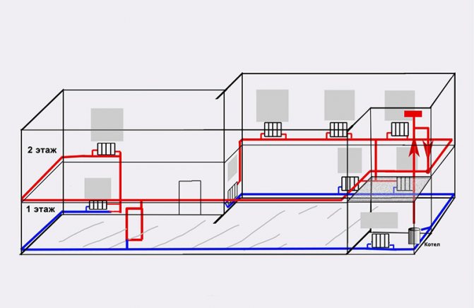
The two-pipe heating system achieves the greatest energy efficiency in buildings with two or more floors. This is achieved due to the greater height difference between the boiler equipment and heating devices. It increases the circulation of the coolant in the pipeline, resulting in a more complete combustion of the fuel in the boiler.
The coolant from the boiler is supplied through a vertical riser, and then along an inclined pipeline to the heating radiators. Surplus heating medium is discharged into the expansion tank. When using the bottom wiring, the inlet pipe is laid at the level of the radiator or above the floor.
The main disadvantage of communications with lower wiring is the high probability of air congestion in the pipeline.
To eliminate this defect, radiators must be equipped with Mayevsky cranes. An alternative is the laying of special air pipes, which ensure the removal of air into the riser and further removal through the expansion tank.
One-pipe system "Leningradka"
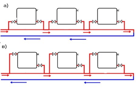
A feature of a one-pipe heating system is a series connection of radiators. The coolant moves along an annular loop. As it progresses, it cools down, so the one-pipe system does not allow for uniform heating of all rooms. "Leningradka" is poorly suited for large buildings. At such facilities, it is better to combine one- and two-pipe systems. Wiring to individual apartments is carried out by means of a two-pipe system, and within a floor - a one-pipe system.
When installing a one-pipe circuit, both types of wiring can be used. The lower one implies laying the pipeline horizontally along the floor. Then the pipes go up to the radiators. This wiring is easy to adjust. If necessary, for example, in the event of a leak, it is easy to completely close it.
With the upper wiring, the coolant is supplied to the highest point of the heating main, from where it is already distributed to the risers. Top routing allows for faster fluid movement and is well suited for natural circulation systems.
Bypass sections
Regardless of the wiring used, when installing the heating system, bypass sections are always made. In one-pipe schemes, they are performed using pipes of a smaller diameter compared to the supply pipe. Also, in such areas, it is possible to install throttling equipment - thermostatic valves.
Since in a one-pipe heating system the heat from the coolant is distributed differently than in a two-pipe heating system, it is necessary to ensure that the radiators are connected correctly. Heating devices located in rooms with the highest heat demand are connected to the supply pipe first. One circuit must have a thermal power of no more than 12 kW. Also, a very strong temperature difference within one circuit must not be allowed.
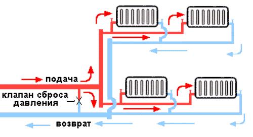
Tichelman's scheme
Tichelman's scheme is a kind of two-pipe systems. Its second name is passing overlapping. It is used in buildings with a large area, for heating industrial premises, hangars, warehouses, etc.It differs from the usual two-pipe scheme by the presence of restricting devices on the supply pipe and return. They provide an even distribution of flows to all radiators. The constricting elements of the supply and return are mounted in a mirror image.
The first radiator is connected using the smallest diameter outlet pipe. The diameter gradually increases. The largest clearance piping is used to connect the supply and return pipes to the very last radiator.
Collector (beam) circuit
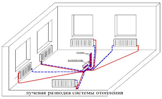
With a collector circuit, each radiator is connected independently, which makes it possible to regulate the temperature of each heater in the system. The manifold (comb) is the most important element. In essence, it is a large-diameter pipe, in which the required number of outlets and one inlet are mounted.
Through the outputs, small circuits are connected to the collector, each of which feeds only one radiator. Each circuit can have different heating parameters. In this case, a hydraulic arrow is used - a type of collector with a large internal volume.
In such a system, the boiler continuously heats up the heating medium circulating in the primary circuit. The withdrawal of water from the hydraulic arrow is carried out at different distances from the cutouts of the contours, due to which different values of the heating modes are obtained. The system with a water arrow is well suited for houses where both traditional radiators and underfloor heating are used as heating devices. If necessary, each circuit can be equipped with its own pumping equipment. In this case, there is no need to take into account the pressure drop values.
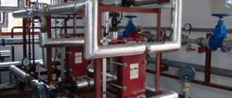
Hydraulic tests
After the installation of the heating system, regardless of the used scheme and wiring, it is mandatory to pressurize it, or hydraulic tests, which are a test of operability.
Pressure testing begins with filling the heating system with water. After that, the pressure in it rises to a level exceeding the operating parameters, and is maintained for some time. Control is carried out using a pressure gauge.
If the system is installed correctly, the pressure in it will remain unchanged. A decrease in this indicator indicates that the connections are leaking and fluid is leaking. If the tests show a leak, all connections are checked, the defects are repaired, and the pressure test is repeated.
Rules and regulations for drawing up an axonometric diagram
Any as-built documentation, including drawings, is performed according to a specific algorithm, using conventions and design rules. Axonometric diagram of heating, air conditioning, ventilation is no exception. Designers, if a computer program is not used, where all the data is already available, use several documents:
- GOST 21.206-93 SPDS;
- GOST 21.602-2003 SPDS.
Information for calculating the power of the ventilation system and other technical data are indicated in SNiPs and GOSTs. From there, such important parameters as the frequency of air exchange, standard values of temperature, humidity are taken. The composition and complexity of the axonometric scheme depends on them.
rules
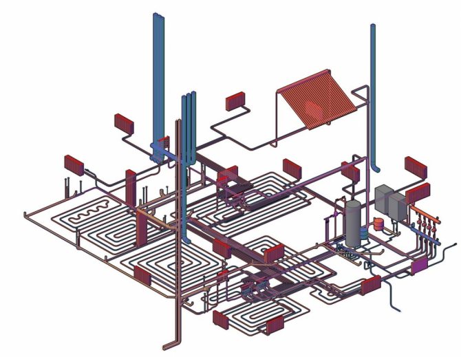
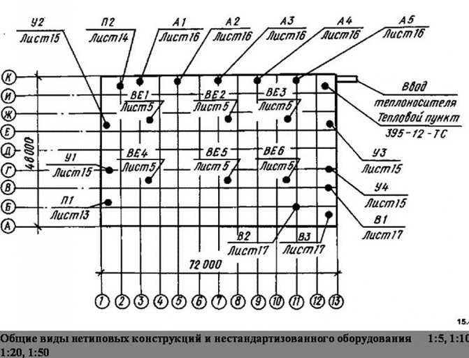
A complex version of the axonometric diagram
The axonometric diagram is carried out in two forms: a sketch and a full drawing. There are few requirements for the sketch, so this is not an official document. A full-fledged axonometric drawing is performed according to all the rules prescribed in state standards:
- The choice of the angle of view. The primary task of the designer is to find the optimal point. For this, a floor plan is used.It is positioned so that the lower part is adjacent to the designer, the left hand looks at the first axis of the building, the right one at the last axis. The facade, which is closer to the designer, or rather its left corner, is the starting point for the axonometric diagram.
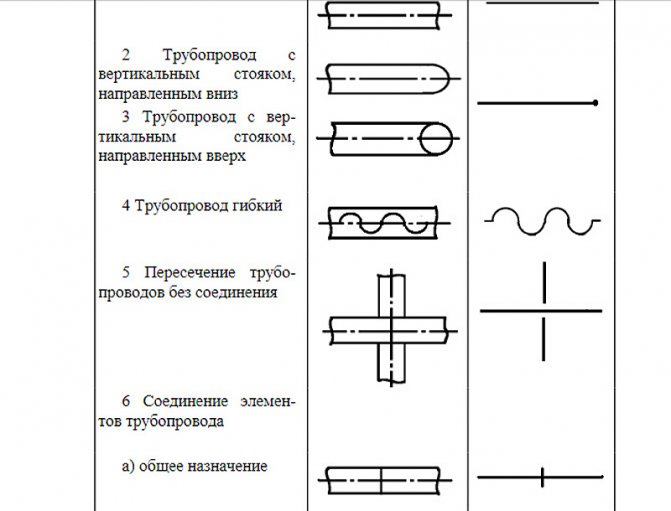
- Determination of the orientation of the duct lines. Everything is simple here. Ventilation ducts running parallel to the nearest or farthest wall of the building are drawn in the form of a horizontal line parallel to the walls. Bends running perpendicular to our wall are drawn at an angle of 450 to the horizontal line. The vertical sections of the ventilation system are drawn vertically.
- Scaling. The axonometric diagram, with the exception of a handwritten sketch, is performed at a certain scale. It does not change within one drawing. If the axonometry in scale does not fit on the sheet, then breaks are allowed (this is when the duct line in the drawing is broken with a dotted line).
Ventilation system assembly sequence technology
Installation and assembly work on ventilation and air conditioning systems includes the following main sequentially performed processes:
- preparation of the facility for the installation of ventilation systems;
- reception and storage of air ducts and equipment;
- completion of air ducts, fittings and ventilation parts; selection and completing of ventilation equipment, and, if necessary, carrying out a pre-installation audit of the equipment;
- assembly of units; delivery of assemblies, parts and elements to the installation site; installation of fastening means;
- installation of equipment;
- enlarged assembly of air ducts;
- installation of main air ducts;
- manufacturing and installation of measurements;
- running-in of installed equipment;
- adjustment and regulation of systems;
- commissioning of systems.
When installing metal air ducts, the following basic requirements should be observed: do not allow the air ducts to rest on the ventilation equipment; vertical air ducts should not deviate from the plumb line by more than 2 mm per 1 m of the duct length; Duct flanges and wafer joints should not be embedded in walls, ceilings, partitions, etc.
The installation of air ducts, regardless of their configuration and location, begins with marking and inspecting the installation sites in order to identify the most convenient ways of transporting and lifting the air ducts and missing fasteners. Then, the lifting means are installed at the design marks, the air duct parts are delivered to the installation work area and the missing embedded parts are shot. Further, enlarged blocks are assembled from individual parts in accordance with the picking list with the installation of clamps for hanging the air ducts.
When assembling on the flanges, make sure that the gaskets between the flanges ensure a tight connection and do not protrude into the duct.
Installation of ventilation equipment is carried out in accordance with standard technological maps in the following order: check the completeness of the delivery; make a pre-assembly audit; delivered to the place of installation; lifted and installed on a foundation, platform or brackets; check the correctness of installation, straighten and fix in the design position; check the performance. When supplying ventilation equipment in bulk, a number of operations for assembling and aggregating equipment are added to the listed technological operations, which can be performed directly at the installation site or assembly site. Installation method and methods of installation of ventilation equipment.
Natural and artificial systems
Ventilation can create air flow naturally or forcedly. The natural movement of air masses is created by differences in temperature and pressure. In forced systems, the air flow is provided by ventilation equipment.
The simplest diagram of a natural ventilation system is presented in conventional typical buildings. In them, door and window openings provide air flow. Air is removed through ventilation ducts and hoods located, as a rule, in the kitchen and in the bathrooms. Natural ventilation has no automatic control, it is reliable, durable and easy to install. The main disadvantage of such systems is dependence on external factors that a person cannot influence. It is impossible to regulate such a system.
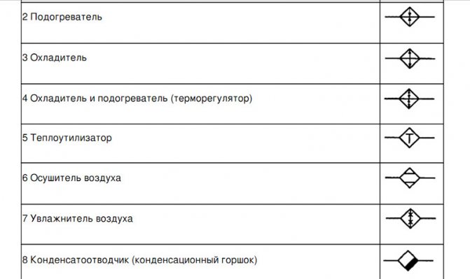
In the case when natural ventilation cannot provide a normal flow of air into buildings, artificial or forced schemes are used. They include various elements - fans, filters, air heaters, humidifiers, etc., allowing to provide normal microclimate values for any premises, depending on their purpose, be it residential, administrative or industrial.
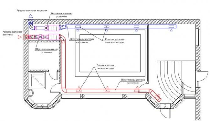
Supply and exhaust systems
These systems differ in the direction of air movement. Supply ventilation brings air into the premises. Depending on the elements included in it, the supplied air can undergo additional preparation - filtration, humidification or dehumidification, etc. The task of the exhaust systems is to remove polluted air from the building.
As a rule, combined supply and exhaust ventilation is used to ensure a normal microclimate in a residential building or industrial premises.
All elements of combined systems must be carefully balanced with each other. Otherwise, overpressure or too little pressure may form, and the effect of a “slamming door” will appear in the room.
Local and general systems
Local ventilation is most often used for industrial premises. The local supply option allows to provide a local supply of clean air, and the extract option allows to remove polluted air from the places where harmful substances accumulate. Local exhaust systems can be used to prevent the spread of toxic substances from production areas throughout the facility. In domestic conditions, local ventilation is widely used in kitchens in the form of an exhaust hood.
General, or general exchange systems are used to ventilate air in all areas of the building. Supply general exchange systems are most often supplemented with elements for filtration and air heating. The hoods are distinguished by a simpler design, since there is no need to process the exhaust air.
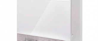
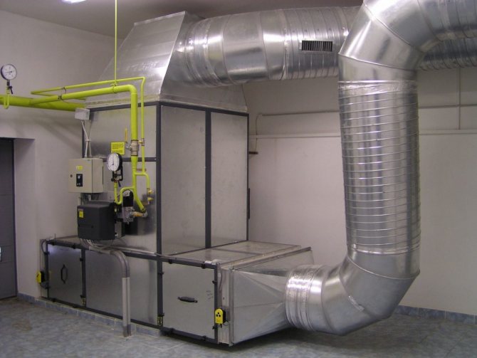
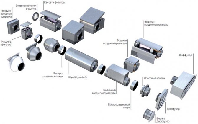
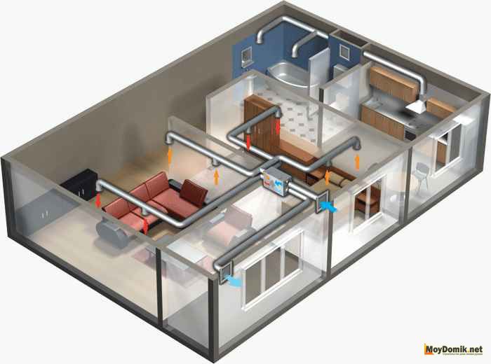
Typesetting and monoblock systems
Typesetting systems are pretty complex. They are assembled from individual components - a fan, filters, chokes, automation, etc. They surpass monoblock ones in the ability to ventilate any objects. They can be installed in a small office or apartment, as well as in public buildings. Such systems are well suited for warehouses, hangars and industrial premises.
Their disadvantage is the complexity of design based on professional calculations and overall dimensions. Powerful systems for industrial premises or large buildings are mounted in a specially equipped ventilation chamber. Low power systems can be mounted behind a false ceiling.
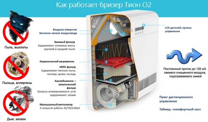
Monoblock ventilation is contained in a single housing. Unlike type-setting systems, it practically does not make noise, so its installation can be carried out in residential buildings without equipment for ventilation chambers. Such systems differ from type-setting and ease of installation.
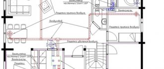
Rules for performing axonometry of supply and exhaust ventilation
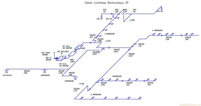
Ventilation axonometry.
Ventilation schemes are performed by engineers in frontal isometric view. This allows us to evaluate communications in three dimensions, which is due to the third axis. This feature distinguishes the axonometric ventilation scheme from plans and sections.You should start drawing a diagram by choosing the direction of the angle of view to the room or the entire structure where the exhaust or inflow will be carried out.
It is recommended to choose the direction from the side that is on the bottom of the drawing. If a sketch is being made, then you can draw as convenient. The main thing is then not to forget about the correct design of the final version. If this is not done on time, then part of the project will have to be redone. All air ducts are shown as solid thick lines. In this case, it is worth observing some features:
- a channel running parallel to the selected angle of view should be executed in the form of a horizontal line;
- vertical air ducts on an axonometric diagram are depicted by vertical lines;
- if the channel is located on the plan perpendicular to the selected viewing angle, then it should be applied to the sheet at an angle of 45 degrees;
- full compliance with the scale.
A number of requirements are put forward to the drawing that must be met by the designer.
Each duct is identified with an extension line. At the same time, the diameter (section size) and air flow rate are indicated. In addition, the height is indicated at different parts of the system. The axonometric ventilation diagram may contain local hoods - umbrellas. They are displayed with a legend. Fans, diffusers and other elements are also depicted with symbols. Equipment is marked with numbers.
Before heating in the garage, you need to insulate it well, preferably outside.
What is the heating wiring in the garage, read this article.
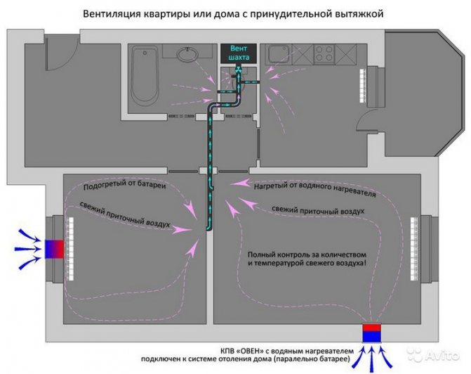
Mixed type
In this case, natural and mechanical air circulation is combined. Alignment can be done in two ways:
- cutting into the air ducts of the natural system of fans in the necessary places;
- installation of a separate mechanical ventilation channel.
The advantage of such a combination is that unpleasant odors do not penetrate into the living rooms. But for this, it is necessary to install supply grilles in the doors through which air will circulate.
Design features
Depending on the purpose of the room, different ventilation configurations are used.
- kitchen. If the area is more than 5 m², it is necessary to equip two air ducts. The first is for general use, and the second with an outlet above the hob, equipped with a fan;
- bathroom. In rooms with high humidity, mechanical air extraction is required. When choosing a fan, stop at more powerful models;
- basement. The best option would be to use two channels for air inlet and outlet. A low basement temperature is conducive to the accumulation of a large amount of moisture. And in the basement, which stores supplies for the winter, dry air is preferable.
You cannot do without installing equipment for circulating air flows in a boiler room or a room with a fireplace. In addition to the natural movement of air, there must be exhaust ducts equipped with fans. The installation of special circulation devices provides additional traction, which will prevent smoke in the room.
Types of ventilation systems
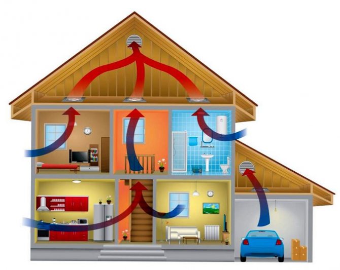
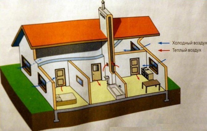
Air circulation in the house
Ventilation in a private house is classified according to the mode of air movement. There are three main types:
- natural;
- forced;
- mixed.
Each type has its own advantages and disadvantages. First of all, the type of ventilation system is determined. For this, all parameters must be taken into account.
Forced system
It is advisable in cases where natural circulation is powerless. You cannot do without the use of such a system in houses made of modern materials:
- expanded polystyrene plates;
- sandwich panels;
- insulation of external walls with polyurethane foam or other synthetic raw materials.
In dirty air conditions, the system should include not only fans, but also cleaning filters.
Calculation of fan parameters
When choosing a device, it is necessary to calculate the main indicator - power. The correct value will ensure sufficient air flow through the ducts and shafts.
Power is calculated using the formula:
P = V * κ,
where V is the volume of the room, κ is the coefficient.
The fan can be started manually or automatically. The second option has a more complex structure. For these purposes, special humidity sensors equipped with a timer are built into the chain.
The value of the coefficient depends on the purpose of the room. Main factors:
- kitchen - 15;
- bathroom - 20;
- toilet - 8.