The three-way valve is a device widely used in a wide variety of designs of household and industrial devices. Accordingly, the same kind of device is used in household gas equipment. Along with various malfunctions of household gas boilers, users often encounter a breakdown of a three-way valve. Agree, it would be nice to find out why this device fails and try to fix it on your own.
Meanwhile, it is not always possible even for professional mechanics to establish the loss of device performance "at first sight". This requires an appropriate check. Therefore, within the framework of our article, we will consider how to check a three-way valve in a gas boiler when there is a suspicion of a malfunction of this mechanism. Let's also talk about the types of the device and its functionality.
Briefly about the mechanism of the three-way valve
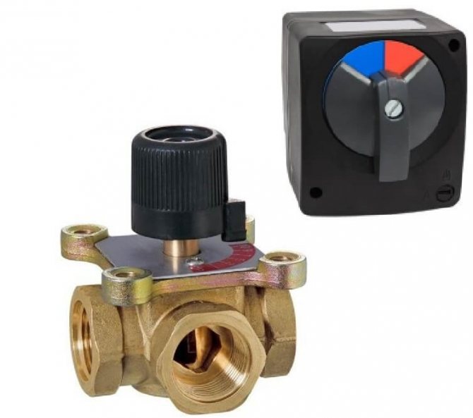
The device of a three-way valve for a household gas boiler and other gas equipment is quite simple, despite its seemingly complex shape. It should be noted that the design of the valves differs significantly for each manufacturer, but the principle of operation actually remains unchanged.
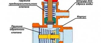
Traditionally instrument case made of bronze. Work items such as stock, springs - are made of steel. Membrane usually made of rubber double ring element... Connecting parts (fittings) can be threaded or soldered, depending on the model of the three-way valve.
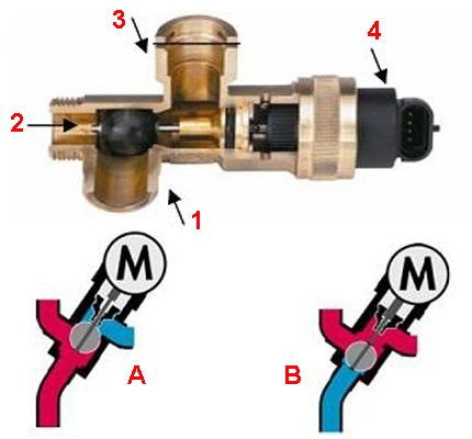
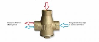
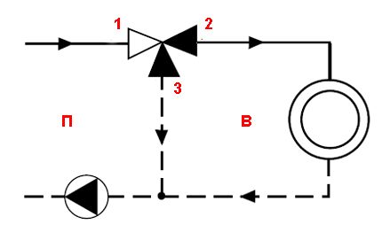
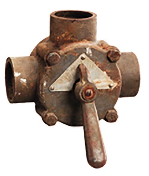
One of the widespread versions of the three-way valve: 1, 2 - angular through passage transport channel; 1, 3 - straight through transport channel; 4 - drive head; A - transport of streams in heating mode; B - transport of streams in hot water supply mode
Usually, an electromechanical drive is used in conjunction with the device. Thanks to its work, two-point control is carried out.
So, the actuator for a three-way valve can be manual, electromechanical (thermostatic, with a thermal head), electric, hydraulic.
The principle of operation of a three-way valve for a gas boiler circuit is approximately the following: when the device is in normally open transport mode, the direct through passage transport channel is accordingly open. The corner duct remains closed.
A different state of the mechanism ensures the opening of the angular transport channel and blocking of the direct transport channel, respectively. Intermediate positions of the stem and flap of the three-way valve are also possible.
We talked in more detail about the device and principle of operation of the three-way valve in the next article.
Replacing the safety valve
Having discovered a breakdown of the safety device, it is impossible to hesitate. It is recommended to immediately replace the breakdown with a new product. Its presence will save you from dangerous situations. The safety of your family depends on this detail.
It is recommended to purchase a device from Italian manufacturers, which are distinguished by an increased price, but are justified by a long service life.
A transparent hose connected to the drain hole will help ensure that the safety device is working properly. The hose is led out into the sewer system or dishes adapted for it.
It is necessary to prepare a plumbing wrench, an adjustable wrench will not interfere.
Algorithm for removing the product to replace it:
- the flowing water heater is disconnected from the electrical network;
- the cold water supply to the boiler is shut off;
- the remaining hot water is drained from the container. For this, the water intake taps are opened;
- the lever on the valve is for forced drainage of liquid residues;
- the cold water supply pipe is removed from the safety device;
- the protection product is being dismantled.
- The part is examined. It may need to be cleaned. In the future, it is installed in place in the reverse order. Or, instead of a broken mechanism, a new one is mounted.
The boiler is connected to the electricity network only after a full set of water in the tank. Otherwise, the boiler will break down.
When buying a new product, you need to check with the seller the pressure indicators at which it works or see the indicator in the technical passport of the product.
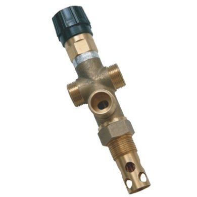
There are models of products in which these numbers are stamped on the case. If the pressure in the home water supply system at the inlet is greater than that for which the device is designed, it is recommended to install an additional pressure reducer at the inlet of the liquid supply to the apartment.
The valve with a reducer reduces the pressure of the liquid at the inlet to the boiler, removes water hammer. A coarse water filter is mounted in front of it. The direction of flow of the liquid is taken into account during installation. The gearbox has a pressure gauge. Its function is to fix the parameters of the water supply system. It controls the pressure of the water supply system.
If the adjustment screw is turned counterclockwise, the outlet pressure from the device will drop. Conversely, a clockwise movement of the screw will increase the pressure.
This is how the gearbox is adjusted. The stiffness of its spring changes, which closes the working valve.
If the regulating valve does not knock down the pressure at the boiler inlet, then an expansion tank is mounted. Its recommended location is between the water heater and the pressure reducing device.
A malfunctioning boiler can result in an electric shock to a family member or flooding of the lower living area. Therefore, when a water heater drips, it is necessary to quickly find the cause of this and eliminate it.
Functional application of the device
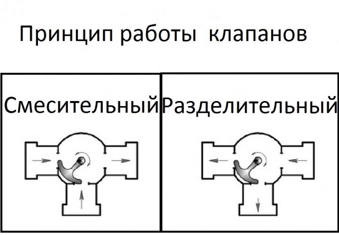
If we consider the flow switching mechanism from the point of view of possible functionality, it should be noted that the devices differ according to the principle of operation:
- Separating.
- Switching.
- Mixing.
The separation principle of operation involves dividing the flow, directing it into two circuits.
The switching function provides for the organization of switching between devices that consume thermal energy. For example, switching between the DHW and heating circuit of a double-circuit gas boiler.
Switching valve functionality (classical scheme): P - primary circuit; B - secondary circuit; 1, 2 - direct transport channel; 3, 2 - corner transport channel
Switching functionality allows you to organize efficient switching between different devices that generate heat energy:
- water heaters;
- heat pumps;
- solar panels, etc.
Another function of a three-way valve for a domestic gas boiler is mixing. It allows you to organize controlled mixing of the working fluid flows (mixing the return flow into the heated coolant).
To do this, it is enough to install a three-way valve on the return pipe of the heating system.
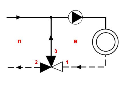
Mixing valve functionality (classical scheme): P - primary circuit; B - secondary circuit; 2, 1 - direct transport channel; 2, 3 - corner transport channel
Now, after a brief acquaintance with the structural details of the device, you can consider the features of checking the operation of the three-way valve installed in the gas boiler circuit.
Major malfunctions and repair methods
Loss of GK functionality leads to the shutdown of all boiler equipment of heating equipment, or partial, when it is impossible to adjust the required heating level in the room, due to the partial opening of the membrane.
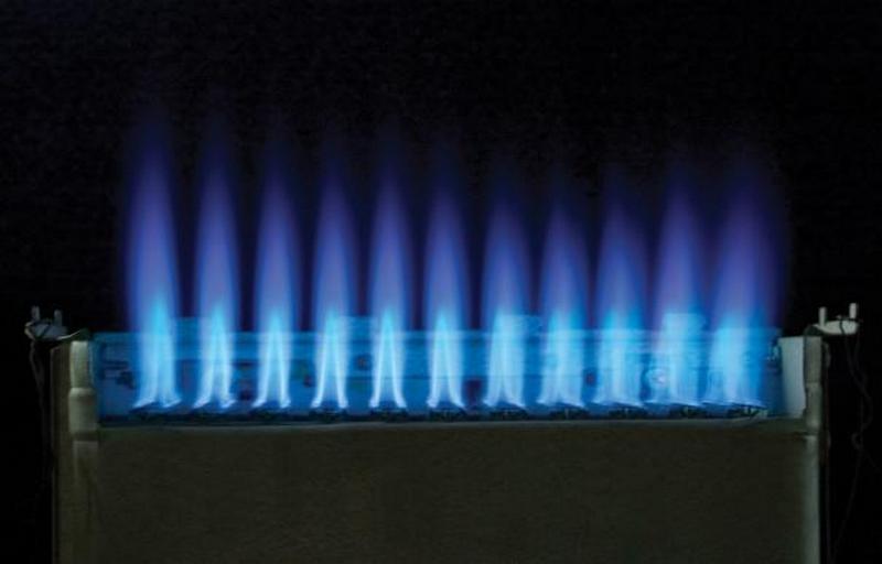
Sometimes situations occur that, on the contrary, lead to a continuous supply of fuel to the burner, when the gas-air valve is constantly open.
All of the above failures must be immediately eliminated, as they can create an emergency in the house. If the user does not know what to do with the faulty valve, immediately close the gas inlet valve, thoroughly ventilate the room and call the representatives of the gas company.
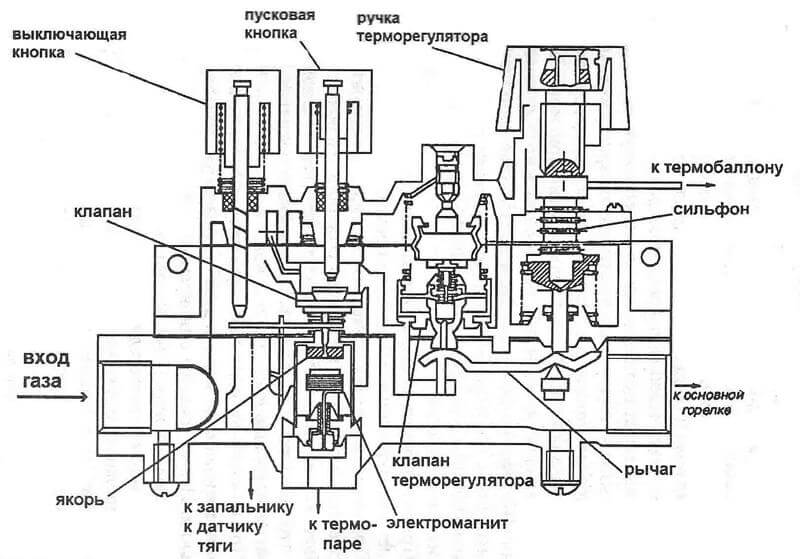
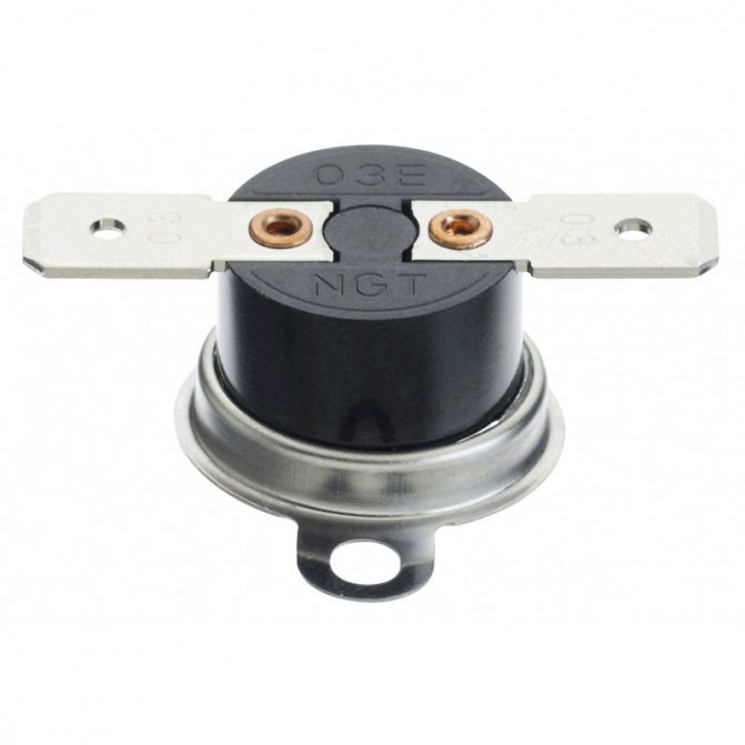
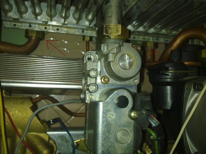
Checking electrical components
It is permissible to test the functionality of the electromagnetic main battery of the cut-off device without dismantling. To perform a check directly on the boiler, you need to turn off the gas supply by turning the valve on the gas pipeline.
The boiler can also remain connected to the power supply. On the regulator of the fuel supply to the burner, there is an electronic unit - a microswitch, which, when the heater is turned on, supplies power to the main technological components.
Voltage supply zones by microswitch:
- ignition system device;
- fan heater;
- electromagnetic coil.
In the event that, by force, for example, with a screwdriver, act on the hydraulic pusher plate of the microswitch, power will be supplied to the boiler automation system.
As a result, the activity of subsequent elements is activated, for example, at the gas valve for the Baxi boiler:
- fan;
- piezo ignition;
- solenoid shut-off valve.
The inspector will hear the sound of a turned on fan, a clicking sound of a piezo ignition and a distinctive click of the valve stem. A similar position of the device shows the performance of the elements, at least in terms of the electrical part.
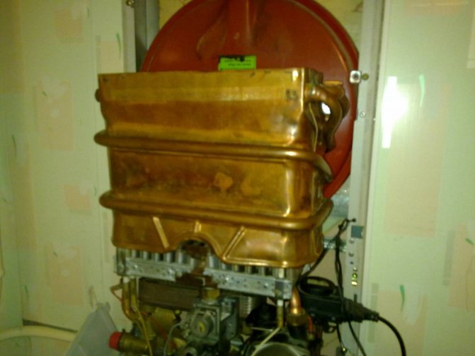
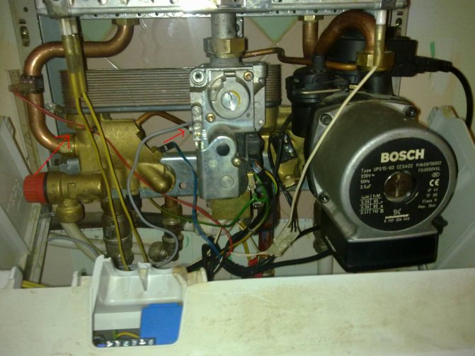
How is the 3-way valve test performed?
A malfunction of the device affects the operation of the gas boiler as a whole. For example, if the supply of the coolant is insufficient, the gas boiler may simply turn off due to overheating. Or, a malfunction of the three-way valve may be accompanied by a lack of proper heating temperature of the coolant in the heating system.
In any case, the device needs to be checked for operability. In this case, in order to carry out diagnostic measures, the regulating device of a gas boiler, as a rule, must be dismantled. Dismantling is relatively uncomplicated, so such work may well be done on its own.
Step # 1 - check valve actuator
Next, we will walk through the verification process step by step, starting by checking the drive. Consider the features of diagnostics of valves with different types of actuators.
Diagnostics of the three-way valve electric drive
The valve stem is traditionally driven by an electric actuator. Therefore, the integrity, availability of power, and the operability of the drive should be checked first.
The integrity of the outer part is checked visually by careful inspection, and the presence of power and the integrity of the internal mechanism - with appropriate instruments.
Diagnostics of the drive end of a three-way valve of a gas boiler using a widespread electrical device - a tester
The drive and all elements of this part of the structure are usually diagnosed with an electrical tester. With this device, you can check both the continuity of the circuits and the presence of the supply voltage. A serviceable actuator must demonstrate the working process when the supply voltage is applied / disconnected - the movement of the valve stem pusher.
It is permissible to check the operation of the electric drive by directly connecting the mechanism to the electric current network, using for this the connector that comes with the drive.This point is clearly highlighted in the video located at the end of the article.
Checking the thermostatic head
If the design of the three-way valve does not provide for the presence of an electric actuator, but is controlled by a thermostatic head, it is necessary to check this part of the system by applying a temperature effect directly to the sensor cylinder.
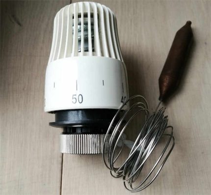
Thermostatic head supplemented with a temperature cylinder. On some models of gas boilers, three-way valve designs are equipped with this type of actuator
For example, you can heat the thermostatic head cylinder using an electric hair dryer.
A functional thermal head should respond to temperature changes and push / pull the valve stem in the same way as an electric actuator does this work.
Checking a Hydraulically Operated Unit
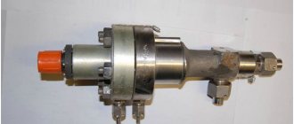
If a valve is used in a gas boiler system that regulates flows and operates on the principle of hydraulic stem control, it is rather difficult to diagnose the operability of such a device directly in the boiler system.
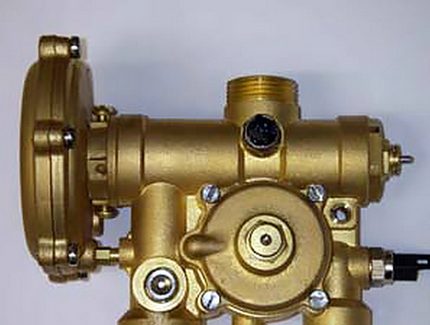
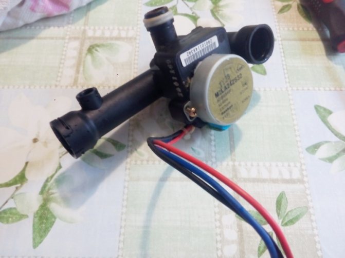
The design of the separating device of a gas domestic boiler, endowed with a hydraulic drive of the control rod. This type of device is quite widespread.
Usually, this kind of structure is subject to dismantling and disassembly, followed by a check of integrity:
- springs;
- seals;
- membranes;
- rings.
Suspicions of the inoperability of the three-way valve, in this case, can be confirmed by starting the gas boiler in test mode. If, at the same time, a violation of the thermal distribution along the working circuits of the system is noted, the valve is not working correctly by 90%.
Step # 2 - checking the thread allocator
The mechanism of the device can wear out during operation. In addition, during the transportation of the coolant, the accumulation of various debris, deposits, etc. in the system is characteristic.
All this can block the operation of the device. Therefore, first of all, it is required to carry out visually checking all available parts.
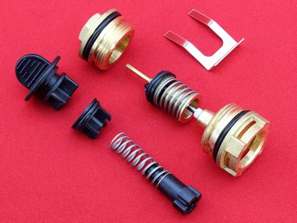
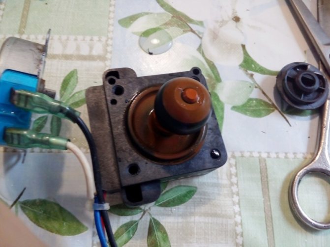
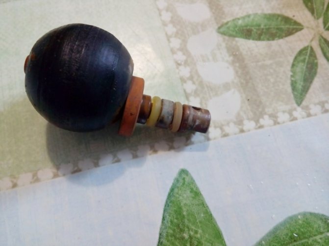
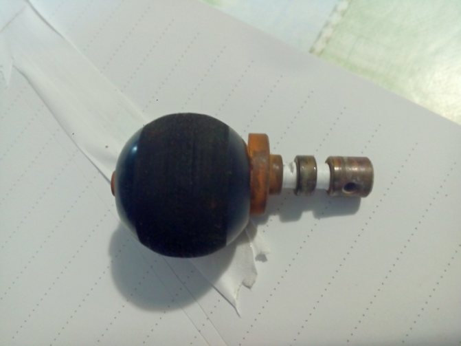
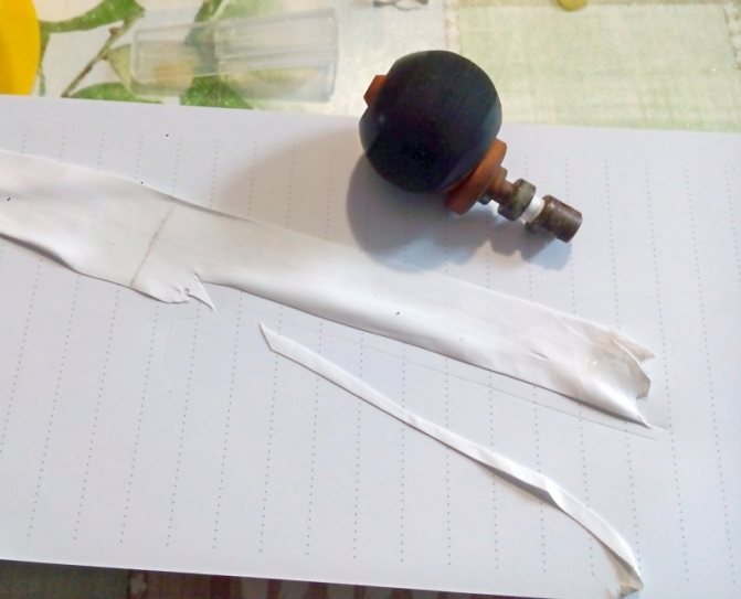
Parts of a three-way valve of one of the manufactured designs, which are subject to inspection in case of suspicion of a malfunction of the control device
Next is executed checking the normal stroke of the diaphragm... As a rule, being in working order, the rod moves smoothly, with some interference. Travel can be verified by applying light force to the end of the stem (actuator outlet) that exits through the valve body capsule orifice.
If the factors of the wedge of the rod stroke along the entire length are not noted and the rod independently returns to its original position from the stop point, then this part of the switchgear is operational.
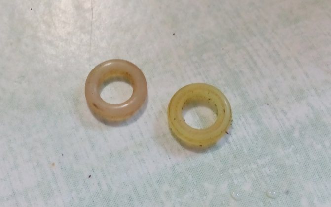
Finally, the elements of the seals are checked - ball or diaphragm, depending on the design. Whereas on rubber seal diaphragms, defects usually appear in the form of tears, then ball seals can deform over time. The deformation factor leads to the loss of a full-fledged seal, respectively, the flow regulation algorithm by the device is violated.

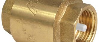
Safety valve use
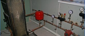
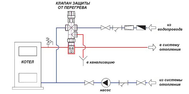
It is not the same as a safety valve. The latter simply relieves pressure in the system, but does not cool it. Another thing is the boiler overheating protection valve, which takes hot water from the system, and instead supplies cold water from the water supply. The device is non-volatile, it is connected to the supply and return mains, water supply network and sewerage system.
At a coolant temperature above 105 ºС, the valve opens and, due to a pressure in the water supply system of 2-5 bar, hot water is displaced from the jacket of the heat generator and cold pipelines, after which it goes into the sewage system. How the solid fuel boiler protection valve is connected is shown in the diagram:
The disadvantage of this protection method is that it is not suitable for systems filled with antifreeze liquid. In addition, the scheme is not applicable in conditions where there is no centralized water supply, because along with a power outage, the water supply from a well or pool will also stop.
Conclusions and useful video on the topic
Below is a useful video material for review, which demonstrates the disassembly of a device that regulates heat flows in a gas boiler. Moreover, the practice of disassembling with your own hands is given.
The distribution device described in the video is equipped with a hydraulic stem drive. Familiarization with this repair practice will help you understand how to check devices of a similar type and repair if defects are found.
Thus, a three-way valve for a domestic gas boiler can be tested in almost any design, regardless of the individual design. The main point is to correctly determine with which drive the switchgear of the gas boiler is used. Information on this issue can be obtained from the documentation for the equipment or by relying on the examples of the drive demonstrations in this article.
Do you have useful information on the topic discussed above and would like to share it with other users? Write your remarks and comments in the block below, add photos, leave your recommendations - the feedback form is located below.
Varieties of valves in a gas boiler
Gas valves (GK) for boilers are systematized according to a number of parameters.
By constructional manufacture:
- Two-way, representing the structure, with two holes - inlet and outlet. Their main purpose is to block the supply or launch of a transit medium in pipes.
- Three-way valve for gas boiler. These designs have 1 inlet and 2 outlets. Such fittings perform a shut-off-regulating and flow-directing role.
- Four-way. These gas valves have 4 openings: 3 outlets, one inlet. They are identical in functionality to a 3-way valve. The presence of an additional entrance expands their field of application for multi-circuit heat supply systems.
The next classification principle is the device control option:
- With manual adjustment. Made in the form of a simple design, the cut-off in them is activated at the moment when the main wheel turns or the link mechanism is triggered. The primary distinguishing qualities of such valves are the highest reliability and relatively low cost.
- Solenoid valve for gas boiler. Due to the fact that the devices are equipped with an electric drive, they are able to operate automatically. The mechanisms are used in main gas pipelines, heating network equipment and industrial installations.
Device for mixing or separating the heat carrier
Valves are divided into two main types:
- Mixing.
- Separating.
Each name speaks for itself. Thermal mixing or mixing works for mixing hot and cold water
... Therefore, the valve is connected to the coolant - the boiler and to the source of cold water supply. The valve is fully open. Without a head, heated water will come from the coolant. Set to 60 degrees, then when this temperature is reached, the valve will press and reduce the flow of hot water, the flow of cold water will increase, the water will be mixed to the desired temperature.
Thermal mixing valves are often used for underfloor heating systems, where the required temperature, as a rule, should not exceed 35-40 degrees. In a mixing system, one outlet has two inlets.
Second - separating, as a rule, it is used to separate streams - into hot and cold water
... It turns out that with one input - two outputs.
Bandwidth calculation
It will not work simply to choose a three-way valve according to the diameter of the heating unit branch pipe or the supply pipeline. The fact is that in the process of automatic control, the element creates a variable hydraulic resistance, which must be overcome by the circulation pump in order to ensure the required flow rate of the coolant. By calculation, the valve is selected in such a way as to pass the required volume of water at different positions of the stem.
The main design characteristic of any 3-way valve is the nominal capacity, denoted by the letter Kvs and expressed in m³ / h. This value, indicated in the product passport, reflects the amount of cold coolant passing through a fully open valve in 1 hour. In this case, the pressure drop in the section before and after the regulator is 1 bar.
Example. If just such a volume of water is passed through a three-way valve with Kvs = 1.6 m³ / h for an hour, the pressure drop (hydraulic resistance) will be 1 bar or 10 m of water column. This is too much for the heating system of a private house, therefore, in the calculations, a real pressure drop is taken - 0.15-0.2 Bar (1.5-2 mWC).
To select a control valve for throughput, you first need to determine the flow rate of the coolant flowing through the regulated line. The following formula is used:
- G is the required water flow rate, m³ / h;
- ∆t is the temperature difference between the supply and return water, usually taken equal to 20 ° С, and in warm floors - 10 ° С.
Example. The house with an area of 100 m² is planned to be heated with floor circuits, which should provide a heat transfer of 10 kW. Then G = 0.86 x 10/10 = 0.86 m³ / h of coolant must be supplied to the distribution manifold.
The next step is to calculate the real coefficient K of the mixing valve throughput, taking into account the pressure drop across it 0.2 Bar by the formula:
For the same example, the value of K will be equal to 0.86 / √0.2 = 0.86 / 0.45 = 1.9 m³ / h. Next, open the catalog of the selected valve manufacturer and select from the line a three-way valve, whose Kvs is equal to or greater than the obtained value. Let's take the well-known Danfoss brand and choose from the VRB3 product series a valve with DN15 nozzles and Kvs = 2.5 m³ / h. The previous denomination in the series is 1.6 m³ / h, which is clearly not enough in our case.
For reference. As a rule, for solid fuel boilers and underfloor heating, arranged in private houses, three-way valves with a nominal diameter of DN15-DN25 are used, no more. But their bandwidth must be calculated. In addition, after selecting the element, it is advisable to check the speed of the flowing coolant, as described in the next video:
An ignorant homeowner who decides to look through the catalog of any well-known company in search of a three-way valve may be confused by the number and variety of products offered. To help you choose the right valve from a wide range of products, we will give you a few recommendations, starting with a list of brands whose catalogs should generally be opened. Here is a list of well-known brands whose products are trustworthy:
- Danfoss (Denmark);
- Herz Armaturen (Austria);
- Honeywell (USA);
- Icma (Italy);
- Esbe (Sweden);
- Caleffi (Italy).
The 3-way thermal valve was not invented yesterday. In the photo - a product of the ESBE company, sample 1935
For reference. The listed companies sell a huge variety of fittings for heating systems, including two-way and four-way valves, electromagnetic dampers and thermostats. From the manufacturers of the post-Soviet countries, we can recommend the products of the Valtec brand (Valtek).
- To protect a solid fuel boiler from condensation, you can choose 2 types of three-way valves - with a fixed setting and a thermal head with a remote sensor. The second option will cost 20-30% more and is not always justified, since a change in the return temperature is unnecessary here.Purchase a regulator with an internal thermostat set at 50 or 55 ° C.
- To control the heating of individual branches and circuits of underfloor heating, a 3-way valve with a remote sensor and a thermostatic head is definitely needed. The sensor flask is installed on the collector or pipeline, whose temperature needs to be monitored.
- Ball (they are also rotary) regulators operate in tandem with an electric drive or are set manually. If you do not want to complicate the circuit and depend on electricity, choose the product that is suitable for the characteristics among the globe valves powered by thermal heads.
- The most popular body material is brass or bronze. Stainless elements are more expensive, and cast iron is afraid of temperature shock and has a decent weight.
- In the schemes, both mixing and three-way dividing valves are used with equal success. But if you are not an expert in the field of heating and assemble the system with your own hands, then it is better to take a valve - mixer. It is easier to deal with it and put it correctly, which the expert will tell in detail about in his video:
Since we have presented a simplified method for calculating and selecting a 3-way valve by capacity, we strongly advise you to consult with knowledgeable people about this. If this is not possible, purchase a valve with a margin, regardless of the price. There is another option: agree with the seller about a possible replacement of the product in case it does not fit.
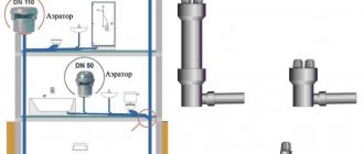
If you need to install water heating in a large cottage heated by a radiator network and underfloor heating, and it is planned to provide DHW from an indirect heating boiler, then you will not be able to do without the help of experienced specialists. You will have to make from 4 to 10 adjustable branches, for each of which you need to calculate and select a three-way valve, and then balance their work in the complex.
A solid fuel boiler is quite complex, it has many different parts and assemblies. The valve is responsible for the temperature control function of the mixer, due to which the air in the pipes heats up evenly and quickly. Uniform heating is impossible without a tap, the temperature in the rooms will vary greatly.
The three-way valve is suitable for all types of boilers for gas and solid fuel models. The crane can differ only in size, configuration, regardless of the brand, it is standard.
The coolant is tap water, it is always available, there are no serious problems during operation. The valve material is stainless steel or bronze. The product may be polymer, but has not yet found its mass distribution.
The tap has 3 holes:
one inlet and two outlets, inside there is a drive that regulates the flow of flows to achieve the optimum temperature.
The principle of operation of the device in any model is standard - cold water is mixed with hot water to the required temperature, the water flows from the branch pipe to the branch pipe until its temperature corresponds to the specified parameters. Further, the actuator opens the flow from the third pipe, water, in which the heated water is already flowing.
He works autonomously, does not need human participation, he is only required to check his work.
Pros of the device:
- Long lasting.
- Easy to install.
- Functional.
- Practical.
- We regulate.
Among the disadvantages are noted:
- Undestination
valve to dirty media. - High price
devices.
Features of product installation
During the installation of three-way valves, many nuances arise. The uninterrupted functioning of the heating system depends on their accounting.The manufacturer encloses instructions for each valve, adherence to which will subsequently avoid many troubles.
General installation guidelines
The main thing is to initially set the valve in the correct position, guided by the prompts indicated by the arrows on the body. Pointers indicate the path of the water flow.
A stands for direct travel, B stands for perpendicular or bypass direction, AB stands for combined input or output.
Based on the direction, there are two valve models:
- symmetrical or T-shaped;
- asymmetrical or L-shaped.
When mounted along the first of them, the liquid enters the valve through the end holes. Leaves through the center after mixing.
In the second variant, a warm stream enters from the end, and a cold stream enters from below. The liquid at different temperatures is discharged after mixing through the second end.
The second important point when installing the mixing valve is that it must not be positioned with the actuator or thermostatic head down. Before starting work, preparation is necessary: water is cut off in front of the installation point. Next, check the pipeline for the presence of residues in it that can cause the valve gasket to fail.
The main thing is to choose a place for installation so that the valve has access. It may have to be checked or dismantled in the future. All this requires free space.
Mixing valve insert
When inserting a three-way mixing valve into a district heating system, there are several options. The choice of the scheme depends on the nature of the connection of the heating system.
When, according to the operating conditions of the boiler, such a phenomenon as overheating of the coolant in the return is permissible, an overpressure necessarily arises. In this case, a jumper is mounted that throttles the excess head. It is installed parallel to the valve mix.
The diagram in the photo is a guarantee of high-quality regulation of the system parameters. If the three-way valve is connected directly to the boiler, which is most often the case in autonomous heating systems, a balancing valve insert is required.
If the recommendation for installing a balancing device is disregarded, significant changes in the flow rate of the working fluid, depending on the position of the stem, can occur in the AB port.
Connection according to the above diagram does not guarantee the absence of circulation of the coolant through the source. To achieve this, it is necessary to additionally connect a hydraulic isolator and a circulation pump to its circuit.
The mixing valve is also installed in order to separate the flows. The need for this arises when it is unacceptable to completely isolate the source circuit, but bypassing the liquid into the return is possible. Most often, this option is used in the presence of an autonomous boiler room.
Drive types and selection criteria
Electrically operated automatic valve
By the type of drive, the models are:
- Mechanical
, the separator is set manually. To monitor the temperature readings, a thermometer is installed on each incoming pipe. - Automatic
, the movement of the membrane depends on the temperature and is carried out independently.
The drive can be:
- Thermostatic
, in which the sensitive element expands under the influence of temperature, begins to press on the valve stem, mixing cold streams with hot ones. - Electric
, in which signals are supplied from the control unit. - Capitate
, the crane is controlled by pressing the head on the drive rod, the drive is applicable when installing a floor heating system.
When choosing a three-way valve, the main thing is the type of actuator. Manual control of the drive is cheaper, but there are few functions.Electric models are expensive, break down quickly, but their versatility does not leave most consumers indifferent. Bronze brass faucet material is durable but also expensive.
The best option is cast iron, copper.
The choice takes into account:
- Media consumption.
- Strapping diagram.
- Working parameters.
Consumption and temperature should be indicated in the design documentation, in the absence of it, the optimal temperature for heating water is indicated in the passport, usually not higher than 50 grams. The flow rate is taken into account when selecting a valve according to its throughput.
The drive type must match the piping diagram.
A simpler scheme for a thermostatic valve, in which water circulates through the third branch pipe to the first, the boiler heats it up, only after that the coolant begins to warm up. Having heated up to the required temperature, out of three possible, the tap opens streams with cold water from the second branch pipe, replacement takes place, cold water leaves, hot water enters the tank with a heat accumulator.
The piping scheme is more complicated when an external controller is installed on the crane.
In this case, two-drive and two-circuit mixers are required. The first circuit is installed next to the heat source and is thermostatic. The second drive is electric, controlled by the controller by supplying sensor signals, the valve maintains the temperature of the coolant.
An important criterion when choosing a device is the range of the set temperatures.
, products, as a rule, in this case have a thermostatic drive in the piping of hot water boilers, floor heating systems. The range of taps depends on the purpose of the products, it is 20-43 grams, 35-60 grams and more. It is advised to stick to the second option when buying.
When assembling the harness, it is worth asking how the crane is checked. If the product is new, it is not difficult to check it, the minimum temperature is set in the range in the third pipe, hot water is poured. After 15 - 20 minutes, the branch pipe should turn off the tap.
You can check the device in an already installed system by measuring the water temperature at the entrance to the boiler, that is, on the reverse side of the pipeline, the value should be the same as on the thermostat.
Strapping diagram: