Air vents: the main task
The device for venting air from the heating system makes it possible to remove gases accumulated in the pipeline and radiators.
The airing of the system occurs for a number of reasons, including
:
- Due to the high content of dissolved gases in the coolant, which has not undergone special training - deaeration. The solubility of gases depends on the temperature of the medium, and when the coolant is heated, the air is separated from the water and accumulates, forming plugs.
- Due to the excessively rapid filling of the circuit with the coolant, the liquid in the branched network does not have time to displace the air in a natural way. The coolant must be poured from the lowest point so that air is forced upward and out through the open valve.
- Due to the penetration of air through the walls of the polymer pipeline, if it is made of a material without a special anti-diffusion coating. When choosing pipes, this point should be taken into account.
- In the course of repair work related to the replacement of elements without completely draining the coolant - in this case, the repaired heating device or circuit is cut off from the rest of the system, and then connected back.
- Loss of tightness.
- As a result of corrosive processes - when oxygen interacts with iron, hydrogen is released from the air molecule, which also accumulates in the system.
Why is the air in the heating system dangerous?
The air dissolved in the coolant gradually destroys steel pipes and radiators, elements of the boiler unit. The corrosive activity of air, which was first dissolved in water and then released during heating, significantly exceeds the parameters of atmospheric air due to the increased oxygen content.
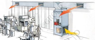
Installation locations of air separators in the system
The gases accumulated in the pipeline not only provoke or accelerate the corrosion of metal elements, but also form air locks that prevent the heating system from fully functioning
:
- Due to gas plugs, the circulation of the coolant deteriorates; in serious cases, the movement of liquid through the pipes can be completely blocked. In such a situation, heating devices cool down quickly.
- Air locks work as a heat insulator, and if gases accumulate in the upper part of the battery, it warms up worse and gives less thermal energy to the room.
- In the presence of air locks, the movement of the coolant along the heating circuit is accompanied by loud gurgling sounds and gurgling, which violates the acoustic comfort in the house.
- Circulation pumps are not designed for pumping gases; when working with an air-filled coolant, the bearing and impeller of the pump unit wear out much faster.
Special air venting devices allow solving problems associated with airing the heating system. It is important to choose the right valves for bleeding air and correctly determine the location of these elements.
What problems does the air vent can solve?
When moving along the contour, the coolant chooses the path of least resistance, and since airy sections are a serious obstacle to the passage of heated water from the boiler, the batteries with accumulations of air mass remain cold or only partially warm up. In addition to the fact that such a phenomenon degrades the quality of heating, it also has a detrimental effect on the performance of all elements connected to the circuit.
If the heating system does not use a valve on the heating radiator to bleed air, then the owner can expect the following troubles:
- failure of the boiler as a result of overheating of the heat exchanger;
- corrosion of heating devices;
- low temperature of the radiators when the boiler is operating at peak performance;
- the risk of defrosting a separate radiator or an entire circuit in severe frosts;
- sudden pressure surges in the circuit, leading to leaks and violation of the integrity of heating devices.
It should be understood that the air in the circuit is a serious nuisance. And how to get rid of the air in the circuit can be found in our article "How to properly bleed air from a heating radiator?" It has physical properties different from water - when heated, it expands more and faster. This leads to serious accidents.
Knowing how to properly air the heating system, the owner will protect himself from unnecessary hassle and costs, and will bring the level of reliability of the heating circuit to a new level.
Types of air vents
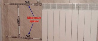
To remove air locks in the central heating system, it is planned to install drain valves on the extreme radiators in each branch. Valve valves make it possible to bleed the air displaced to the extreme point of the branch when the system is filled with a coolant.
Autonomous heating systems, as well as new radiators connected to the central heating network, are equipped with special air vent valves. There are two types of devices - an automatic air release valve and a manual valve (Mayevsky valve).
The devices are selected taking into account the principle of operation and ease of use, they are mounted in those places of the heating circuit where the risk of formation of air locks is greatest - on the upper manifold of each radiator, at the highest point of the heating system.
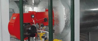
Automatic air vent
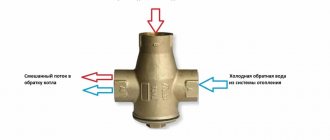
The automatic air valve consists of a hollow cylinder with a plastic float inside. The device is installed vertically, its internal chamber is normally filled with a coolant, which flows under pressure through an opening in the lower part of the chamber. The air vent is equipped with a needle outlet valve - it is to this valve that the float is attached to the lever.
The principle of operation of the automatic air vent
When an air lock forms in the pipeline, it tends to the highest point of the radiator or the heating circuit as a whole. If an air valve operating in automatic mode is installed in this place, the coolant from its inner chamber is displaced by gases. When the liquid is displaced, the float goes down and opens the valve, as a result of which gases are released from the heating pipeline, and the chamber is again filled with coolant.
Note! The valve for automatically venting air from the heating system becomes silted over time, overgrown with scale. This leads to jamming of the mechanism, loss of valve tightness - moisture begins to seep through it. Such a device requires replacement - automatic air vents cannot be repaired.
The amount depends on the characteristics of the heating system.
Device required for installation
:
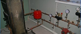
- as part of the safety group of the boiler unit at the outlet of the water jacket, where the coolant is heated to the maximum temperature;
- at the highest point of vertical risers - it is there that gaseous substances rise and accumulate;
- on distribution manifolds of underfloor heating so that air can be vented from the circuits;
- on U-shaped loops made of polymer pipes, which are equipped to compensate for the thermal expansion of the pipeline.
Manual air vent
The manually operated drain valve is commonly known as the Mayevsky tap.This device has no moving elements, therefore it is more durable and more reliable than automatic.
The cylindrical body of the air vent is provided with an external thread. The longitudinal through hole in the housing is closed by a screw with a conical end. A circular channel extends from the central hole.
The principle of operation of the Mayevsky crane is extremely simple: unscrewing the screw frees the passage into the side channel, due to which the accumulated gases go out through the hole in the body. After removing the airlock, the screw is tightened into place.
Type of manual angle air vent with shut-off cone
Manual air vent valves are designed for pipe mounting as standard. But the greatest demand is for Mayevsky's radiator taps, which are mounted on sectional and panel-type heating devices.
How to remove an airlock
Ideally, gases rise to the highest points in the circuit where air vents are installed and are vented from there by manual or automatic valves. In practice, errors in the design or installation of the pipeline lead to the formation of air jams in hard-to-reach places.
To remove such a plug, it is necessary to find its location - by the murmur of the coolant flowing through the air-filled section, by the relatively low temperature of the pipe or radiator, by the ringing sound when the pipes are tapped.
An increase in the temperature of the coolant and / or pressure in the system will help to expel the plug from the autonomous heating system. To apply pressure, it is necessary to open the make-up valve and the drain valve closest to the air plug (in the direction of flow). The water entering the system increases the pressure and forces the plug to move. After making sure that the plug came out through the valve (it stops hissing), the system is returned to normal operating mode.
Removing an air lock from the heating system
In more complex cases, they act not only by pressure, but also by temperature. The coolant must not be heated above the maximum permissible values, so as not to damage the heating system.
Important! The regular formation of a plug in the same place indicates miscalculations in the project or incorrect installation. It is recommended to install an air vent in the problem area by cutting a tee into the pipeline.
Selection principles
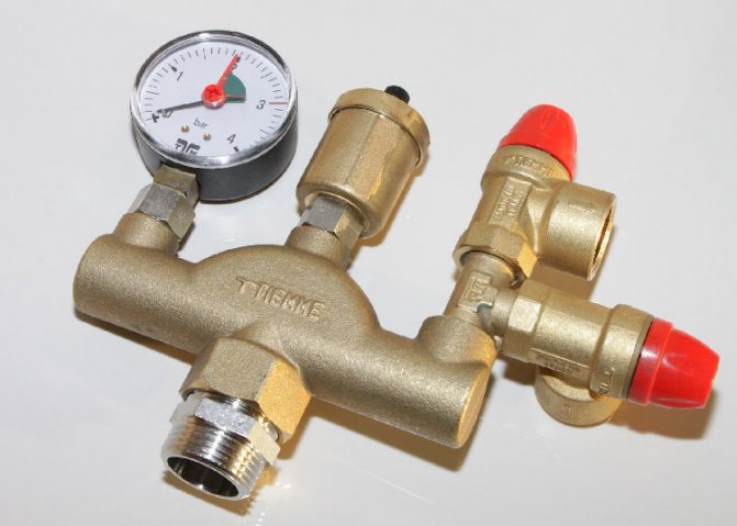
Air valves for the heating system can be part of a safety group or a manifold kit for underfloor heating, supplied with heating devices.
The air vent is selected taking into account its operating parameters (maximum allowable temperature and pressure), they must correspond to the characteristics of the heating system. By design, they are divided into straight and angular devices, horizontal and vertical.
Mayevsky's cranes differ in the method of unscrewing the working screw
:
- with a stem head for a special key (the inconvenience is that the key may not be at hand at the right time);
- with a non-removable handle (cannot be used in places accessible to young children, in order to eliminate the risk of burns from the heated coolant;
- with a slot for a flat screwdriver (the most convenient and safe option).
In order to equip your heating system with a reliable air relief valve, it is recommended to choose well-known brands. Cheap products made of fragile silumin imitating brass should be avoided.
Many different elements are responsible for the normal functioning of the water heating system, which are an integral part of the circuit of any complexity. One such element is the air valve for heating, which is a small but very important part of a simple design. This article will discuss how to choose the right item depending on the installation location.
Equipment installation
An air valve for non-ventilated sewers is not the only installation option. The valves can duplicate the classic ventilation scheme, be installed instead of or together with fan structures.
The main requirement when choosing an installation site is to keep the ambient temperature above 0 ° C. This will avoid freezing and malfunction of the equipment.
Height matters, on which the installation of an air valve for the sewerage is carried out.
- In the absence of a drain for draining water in the floor, the valve is placed 10 cm higher than the location of the highest outlet of the plumbing fixture or water-consuming equipment.
- If there is a ladder, the valve is placed 35 cm above the floor level.
Important: Observing these distances ensures that the waste valve is protected from contamination.
It is necessary to choose an installation site in such a way that easy access to it for inspection and repair is provided. If a vacuum valve for sewage with a diameter of 110 mm is supposed to be closed with panels, plasterboard or other structure, it is necessary to provide such a structure with special doors or hatches in order to avoid the need for complete dismantling during repair work.
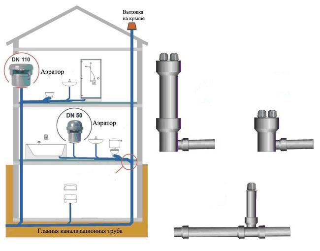
Installation options for sewer aerators
The place of installation is the free end of the pipe or its socket.
In some cases, it is advisable to install an air drain valve in the attic or in a specially designated utility room.
After choosing the installation site and purchasing the product that fully meets the requirements and is suitable in terms of geometric parameters (diameter), the valve is installed in accordance with its design (on the thread, into the flange, using a coupling). It is important to ensure the tightness of the joints and check this parameter after the completion of the installation work.
There is no need to confuse the air and sewage check valve. We have a separate article on the latter on our portal.
If you are interested in knowing what the sewer pipe is used for in a private house, then we also talked about this in another article.
And the features of independent construction of a peat toilet on the site can be found here https://okanalizacii.ru/postrojki/tualet/torfyanoj-tualet-dlya-dachi-svoimi-rukami.html
Purpose and types of air vents
It is easy to guess the purpose of the device by its name. The element is used in the circuit in order to remove air from the system or individual devices and units, which appears there under the following circumstances:
- while filling the entire pipeline network or individual branches of the system with water;
- as a result of suction from the atmosphere due to various malfunctions;
- during operation, when oxygen dissolved in water gradually passes into a free state.
For reference.
In industrial boiler houses, make-up water goes through a deaeration stage (removal of dissolved air) before entering the boiler. As a result, tap water, initially containing up to 30 g of oxygen per 1 m3, becomes serviceable with an indicator of less than 1 g / m3. However, such technologies are quite expensive and are not used in private housing construction.
The task of the air vent is to release air from the heating system in order to avoid the formation of air pockets. The latter seriously impede the free circulation of the liquid, due to which some parts of the system can overheat, while others, on the contrary, can cool. In addition to air, other gases can accumulate in pipelines. For example, with a high content of dissolved oxygen in the coolant, the corrosion process of steel pipes and boiler parts is significantly accelerated. A chemical reaction takes place with the release of free hydrogen.
In the current schemes of house heating systems, 2 types of air vents are used, differing in design:
- manual (Mayevsky cranes);
- automatic (float).
Each of these types is installed in different places where there is a danger of an airlock. Mayevsky's cranes have a traditional and radiator design, and the configuration of air vents is straight and angular.
In theory, an automatic air vent can be installed in all necessary places. But in practice, the scope of application of machines is limited for many reasons. For example, the device of the Mayevsky crane is simpler and has no moving parts, so it is more reliable. The manual faucet is a cylindrical body made of plumbing brass with an external thread. A through hole is made inside the body, the passage in which is blocked by a screw with a tapered end.
A circular calibrated channel extends from the central hole. When you unscrew the screw between the two channels, a message appears, allowing air to escape from the system. During operation, the screw is completely tightened, and in order to discharge gases from the system, it is enough to unscrew it a couple of turns with a screwdriver or even by hand.
In turn, the automatic air valve is a hollow cylinder with a plastic float inside. The working position of the device is vertical, the inner chamber is filled with a coolant flowing through the bottom hole under the influence of pressure in the system. The float is mechanically attached to the needle outlet valve by means of a lever. The gases coming from the pipelines gradually displace the water from the chamber and the float begins to descend. Once the liquid has been completely expelled, the lever will open the valve and all air will quickly leave the chamber. The latter will immediately be filled with coolant again.
The internal moving parts of the automatic air vent are gradually scaled up and the working holes are silted up. As a result, the mechanism is seized, and the gases come out slowly, water begins to flow through the unit with the needle. Such an air vent valve is easier to replace than to repair. Hence the conclusion: auto air vents are installed only in those places where you cannot do without them. They are selected for:
- boiler safety groups, where the temperature of the coolant is the highest;
- the highest points of vertical risers, where all gases rise;
- a distribution manifold for underfloor heating, where air accumulates from all heating circuits;
- loops of U-shaped expansion joints made of polymer pipes, turned upwards.
When choosing a device, you should pay attention to 2 parameters: maximum operating temperature and pressure. If we are talking about a heating scheme for a private house with a height of up to 2 floors, then, in principle, any automatic valve for air release is suitable. The minimum parameters of the air vents on the market are as follows: operating temperature up to 110 ºС, the pressure range in which the device works effectively - from 0.5 to 7 bar.
In high-rise cottages, circulating pumps can develop a higher pressure, so when selecting them, you need to focus on their performance. As for the temperature, in private residential networks it rarely exceeds 95 ºС.
Advice.
Experts - practitioners recommend purchasing air vents with an upward exhaust pipe. According to reviews, the device with a side outlet begins to leak much more often. In addition, the vertical position of the housing must be strictly observed during installation.
Manual air vents for heating systems (Mayevsky taps) are most often used for installation on radiators. Moreover, many manufacturers of sectional and panel devices complete their products with gas removal valves. In this case, there are 3 types of air vents according to the method of unscrewing the screw:
- traditional, with slots for a screwdriver;
- with a stem in the form of a square or other shape under a special key;
- with a handle for manual unscrewing without any tools.
Advice. The third type of product should not be purchased for a home where preschool children live. Accidentally opening the tap can lead to severe burns from the hot coolant.
Car device
The radiator is designed to transfer heat from the coolant to the air stream, i.e., it is the main heat exchange unit of the engine cooling system. The general arrangement of the radiator of the liquid cooling system of the engine is shown in Figure 3. The radiator arrangement is shown in more detail in Figures 1 and 2.
The upper 9 (Fig. 1, a) and the lower 15 radiator tanks are connected to the core 12. The filler neck 8 with sample 7 and the branch pipe for connecting a flexible hose that supplies the heated coolant to the radiator are soldered into the upper tank. On the side, the filler neck has an opening for a steam pipe.
A branch pipe of the discharge flexible hose 13 is soldered into the lower tank.
Side posts 6 are attached to the upper and lower tanks, connected by a plate soldered to the lower tank. The pillars and fins form the frame of the radiator.
The main heat exchange element of a radiator is its core, which consists of numerous tubes connected to form honeycombs using metal plates or tapes. Radiator tubes can be round, oval or rectangular. In this case, the smaller the flow area and the thinner the tube wall, the higher its heat exchange capacity. For the passage of the coolant, suture or solid-drawn tubes made of brass tape with a thickness of up to 0.15 mm are used.
The cores of car radiators can be plate-tubular or tape-tubular. In tubular-plate radiators, the cooling tubes are staggered relative to the air flow in a row or at an angle (Fig. 2, a-d). The finning plates are flat or wavy. To enhance heat transfer, special turbulators in the form of bent slits can be made on them, which form narrow and short air channels located at an angle to the air flow (Fig. 2, e).
In tubular-strip radiators (Fig. 2, e), the cooling tubes are arranged in a row. The lattice tape is made of copper with a thickness of 0.05 ... 0.1 mm. To enhance heat transfer, turbulence of the air flow is created by making curly stampings or bent cuts on the tape (Fig. 2, g).
Recently, radiators made of aluminum alloy have become widespread, which are lighter than brass ones and cheaper, but their reliability and durability are inferior to radiators made of brass alloys. In addition, brass radiators are easier to repair by soldering. Parts and structural elements of aluminum radiators are usually connected by rolling with the use of sealing materials.
The radiator is connected to the engine cooling jacket by branch pipes and flexible hoses, which are attached to the branch pipes with clamping clamps. This connection allows relative displacement of the engine and radiator without compromising the tightness of the liquid cooling system.
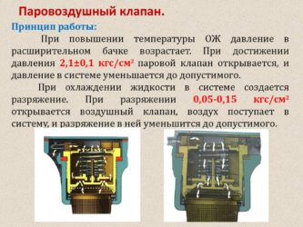
Plug 7, which closes the radiator neck 8, consists of housing 18 (Fig. 1, b), steam 22 and air 25 valves and a locking spring 21.
On the post 20, by means of which the closing spring is attached to the body, a steam valve is installed, pressed by the spring 19. The air valve 25 is pressed by the spring 26 against the seat 27. The tight fit of the valves to the seats is achieved by installing rubber gaskets 23 and 24. If the rubber gaskets are damaged, the cooling system becomes open and the coolant boils at a temperature of 100 ˚С. With serviceable valves, the pressure in the system is slightly higher than the ambient pressure and the boiling point of the coolant is 108 ... 119 ˚С.
If the coolant boils in the cooling system, the vapor pressure in the radiator increases.At a pressure of 145 ... 160 kPa, the steam valve 22 opens, overcoming the resistance of the spring 19. The cooling system is in communication with the atmosphere, and the steam leaves the radiator through the steam outlet pipe 17.
After the liquid has cooled, the vapor is condensed and a vacuum is created in the cooling system.
At a pressure of 1 ... 13 kPa, the air valve 25 opens and into the radiator through hole 28, and the valve begins to flow air from the atmosphere.
The steam and air valves prevent possible damage to the radiator due to high pressure, both on the outside and on the inside.
If an expansion tank is used in the cooling system, the valves can be placed in its plug.
To regulate the flow of air passing through the core of the radiator in the cooling system of trucks and buses, as well as cars of obsolete designs, blinds with a drive from the driver's cab are used (Fig. 1, a).
Blinds are made of a set of vertical or horizontal leaf-sash made of galvanized iron, which are united by a frame and a hinge device that provides simultaneous (or group) rotation of the plates around the axis. When the handle 4 is moved forward until the shutters fail, the shutters open completely, and the air passes freely between the radiator tubes, taking away excess heat from them.
To regulate the temperature regime, the blinds drive handle can be installed on the latch 5 in any intermediate position. In some cars, blinds are used in the form of canvas or leather curtains, spring-loaded in a special tube and equipped with a lifting and lowering mechanism.
Modern passenger cars, as a rule, are not equipped with louvers to regulate the air flow to the radiator - more often systems are used to automatically turn on and off the cooling fan using electrical or hydraulic devices. This improves driving comfort.
The efficiency of blowing air into the radiator core is increased by the use of a guiding casing - diffuser 16, which is attached to the radiator frame and surrounds the cooling system fan in a circle. The diffuser directs the air flow through the core, eliminating air movement past the radiator.
***
Since the radiator is made of thin-walled tubes and plates, it is a very delicate and fragile device. Therefore, when servicing and repairing, it is necessary to handle the radiator with care so as not to damage the parts of the core, pipes or tanks.
During the summer period, drivers often use water as a coolant - it is cheaper and more efficiently involved in heat transfer processes due to its physical properties. But such savings can lead to damage and even destruction of engine parts and assemblies.
It should not be forgotten that antifreezes reduce the formation of scale on the walls of the cooling jacket of the block and the block head.
In addition, in modern cars, low-freezing fluids often serve not only to cool the engine, but also to lubricate some components, for example, the bearings of the liquid pump of the cooling system. Water cannot perform such functions.
When using water in a liquid cooling system instead of low-freezing liquids during the cold season, it should be carefully removed from the radiator and engine cooling jacket when storing the car in unheated rooms and in an open parking lot.
Otherwise, frozen water (as you know, water expands when freezing) can break the tightness of the system, damaging the butt joints of parts and even rupture the tubes of the core and radiator tanks, the block head and the engine block crankcase.
For this reason, it is necessary to make sure that the water has completely drained out through the open taps on the block and the radiator (the radiator cap must be removed in this case), and then purge the system with several turns of the crankshaft using the starter or even by running the engine for a few seconds without coolant.
Types of automatic air dumpers
In total, there are three types of these devices - despite this, the operation of the automatic air vent, or rather its principle, remains unchanged. In all cases, the same needle valve and the same float that opens and closes it are used - the only difference is in the position of the body relative to the connecting pipe, i.e. threaded connection.
Direct automatic
air valve for heating. The most common automatic venting device. It is intended only for vertical installation - in the sense that if you suddenly decide to use it for a battery, then you will additionally need a corner at 90 degrees. The optimal area of their application is pipelines, or rather their upper points, where, according to all the laws of physics, the air formed in heating rushes. If it were not for such devices, then it would be very inconvenient to discharge air at the highest points of heating systems. In addition, some heating system equipment is equipped with automatic dumpers with straight connecting pipes. For example, the automatic air valve is an integral part of the boiler safety group, which also includes a pressure gauge and an explosion valve. Air vents are also equipped with indirect heating boilers and other equipment, at the top of which there is a possibility of air accumulation.
Valve on radiator for air relief
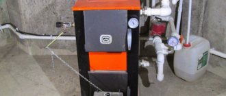
Safety valve
In most models of modern boilers, manufacturers provide a safety system, the "key figure" of which is the safety fittings included directly in the boiler heat exchanger or in its piping.
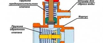
The purpose of the safety valve in the heating system is to prevent the pressure in the system from increasing above the permissible level, which can lead to: destruction of pipes and their connections; leaks; explosion of boiler equipment The design of this type of valve is simple and unpretentious.
The device consists of a brass body, which houses a spring-loaded closing diaphragm connected to a stem. Spring resilience is the main factor that
keeps the diaphragm in the locked position. The adjusting handle adjusts the compression force of the spring.
When the pressure on the diaphragm is higher than the set one, the spring is compressed, it opens and the pressure is released through the side hole. When the pressure in the system cannot overcome the elasticity of the spring, the diaphragm will return to its original position.
Tip: Purchase a safety device with pressure regulation from 1.5 to 3.5 bar. Most models of solid fuel boiler equipment fall into this range.
Air vent
Air congestion. As a rule, there are several reasons for their appearance:
- boiling of the coolant;
- high air content in the coolant, which is automatically added directly from the water supply;
- As a result of air leaks through leaking connections.
The result of air locks is uneven heating of radiators and oxidation of the inner surfaces of the CO metal elements. The air relief valve from the heating system is designed to remove air from the system in automatic mode.
Structurally, the air vent is a hollow cylinder made of non-ferrous metal, in which a float is located, connected by a lever with a needle valve, which in the open position connects the air vent chamber to the atmosphere.
In working condition, the inner chamber of the device is filled with a coolant, the float is raised, and the needle valve is closed. If air enters, which rises to the upper point of the device, the coolant cannot rise in the chamber to the nominal level, and therefore, the float is lowered, the device operates in the exhaust mode. After the air is released, the coolant rises in the chamber of this kind of fittings to the nominal level, and the float takes its regular place.
Check valve
In gravity CO, there are conditions under which the coolant can change the direction of movement. This threatens to damage the heat exchanger of the heat generator due to overheating. The same can happen in sufficiently complex COs with forced movement of the coolant, when water, through the bypass pipe of the pumping unit, gets back into the boiler. The mechanism of action of the check valve in the heating system is quite simple: it passes the coolant only in one direction, blocking it when moving back.
There are several types of this kind of fittings, which are classified according to the design of the locking device:
- disc-shaped;
- ball;
- petal;
- bivalve.
As it is already clear from the name, in the first type, a steel spring-loaded disk (plate), connected to the stem, acts as a locking device. In a ball valve, a plastic ball acts as a shutter. Moving "in the right" direction, the coolant pushes the ball through the channel in the body or under the cover of the device. As soon as the circulation of water stops or the direction of its movement changes, the ball, under the influence of gravity, takes its original position and blocks the movement of the coolant.
In the petal, the locking device is a spring-loaded cover, which is lowered when the direction of water in CO changes under the action of natural gravity. The bivalve element is installed (as a rule) on large diameter pipes. The principle of their work does not differ from the petal one. Structurally, in such an armature, instead of one petal, spring-loaded from above, two spring-loaded flaps are installed. These devices are designed to regulate temperature, pressure, and stabilize the work of CO.
Balancing valve
Any CO requires hydraulic adjustment, in other words - balancing. It is carried out in various ways: with a correctly selected pipe diameter, washers, with different flow cross-sections, etc. The most effective and at the same time simple element of setting up the operation of CO is a balancing valve for the heating system.
The purpose of this device is that the required volume of coolant and the amount of heat can be supplied to each branch, circuit and radiator.
The valve is a conventional valve, but with two fittings installed in its brass body, which make it possible to connect measuring equipment (manometers) or a capillary tube with an automatic pressure regulator.
Principle of operation
balancing valve for the heating system is as follows: Turns the adjusting knob to achieve a strictly defined flow rate of the heating agent. This is done by measuring the pressure at each nozzle, after which, according to the diagram (usually supplied by the manufacturer to the device), the number of turns of the adjusting knob is determined to achieve the desired water flow rate for each CO circuit. Manual balancing regulators are installed on circuits with up to 5 radiators. On branches with a large number of heating devices - automatic.
Bypass valve
This is another CO element designed to equalize the pressure in the system. The principle of operation of the bypass valve of the heating system is similar to the safety one, but there is one difference: if the safety element bleeds off excess coolant from the system, then the bypass valve returns it to the return line past the heating circuit.
The design of this device is also identical to the safety elements: a spring with adjustable elasticity, a shut-off diaphragm with a stem in a bronze body. The flywheel adjusts the pressure at which this device is triggered, the membrane opens the passage for the coolant. When the pressure in CO stabilizes, the membrane returns to its original place.
Based on materials from the sites: ventilationpro.ru, stroisovety.org
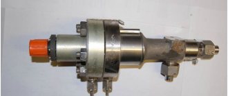
Air-steam pumps and fittings
Steam locomotives and railway tenders are equipped with tandem or compound steam-air pumps (Table 1-10) and Westinghouse brakes. Fig. 1. Tandem pump No. 208: 1 - high pressure air cylinder; 2 - low pressure air cylinder; 3 - automatic oiler 1053, 4 - steam cylinder; 5 - steam distribution cover; 6 - grease nipple No. 202, 7 - discharge pipe; 8 - suction valves; 9 - steam supply pipe with a diameter of 1 ′
Table 1. Characteristics of steam-air pumps
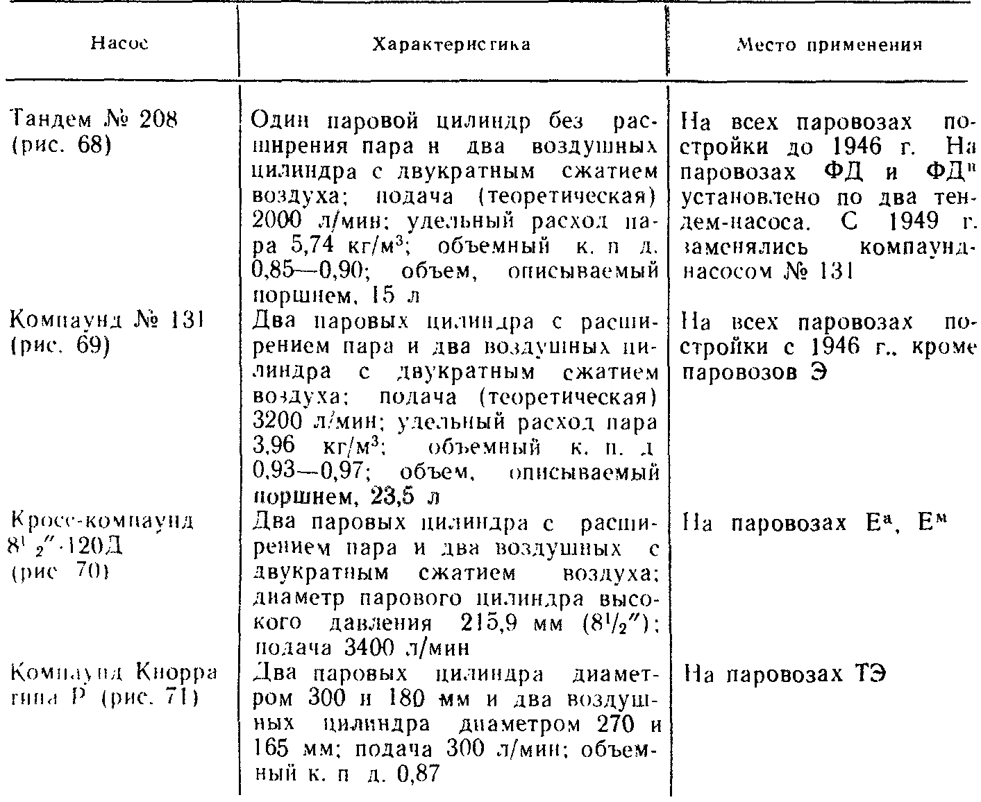
Note. Air-steam pumps No. 204 and 131 and governors of pumps No. 91 and 279 and 1952 are discontinued. Fig. 2. Compound pump No. 131 1 - air cylinder block, 2 - steam cylinder block; 3 - grease nipple No. M-5; 4 - outlet pipe with a diameter of 2 ″; 5 - 2 ″ diameter injection pipe; 6 - suction pipe with a diameter of 2 ″; 7 - steam supply pipe with a diameter of 1.5 '; 8 - pump stroke regulator No. 91
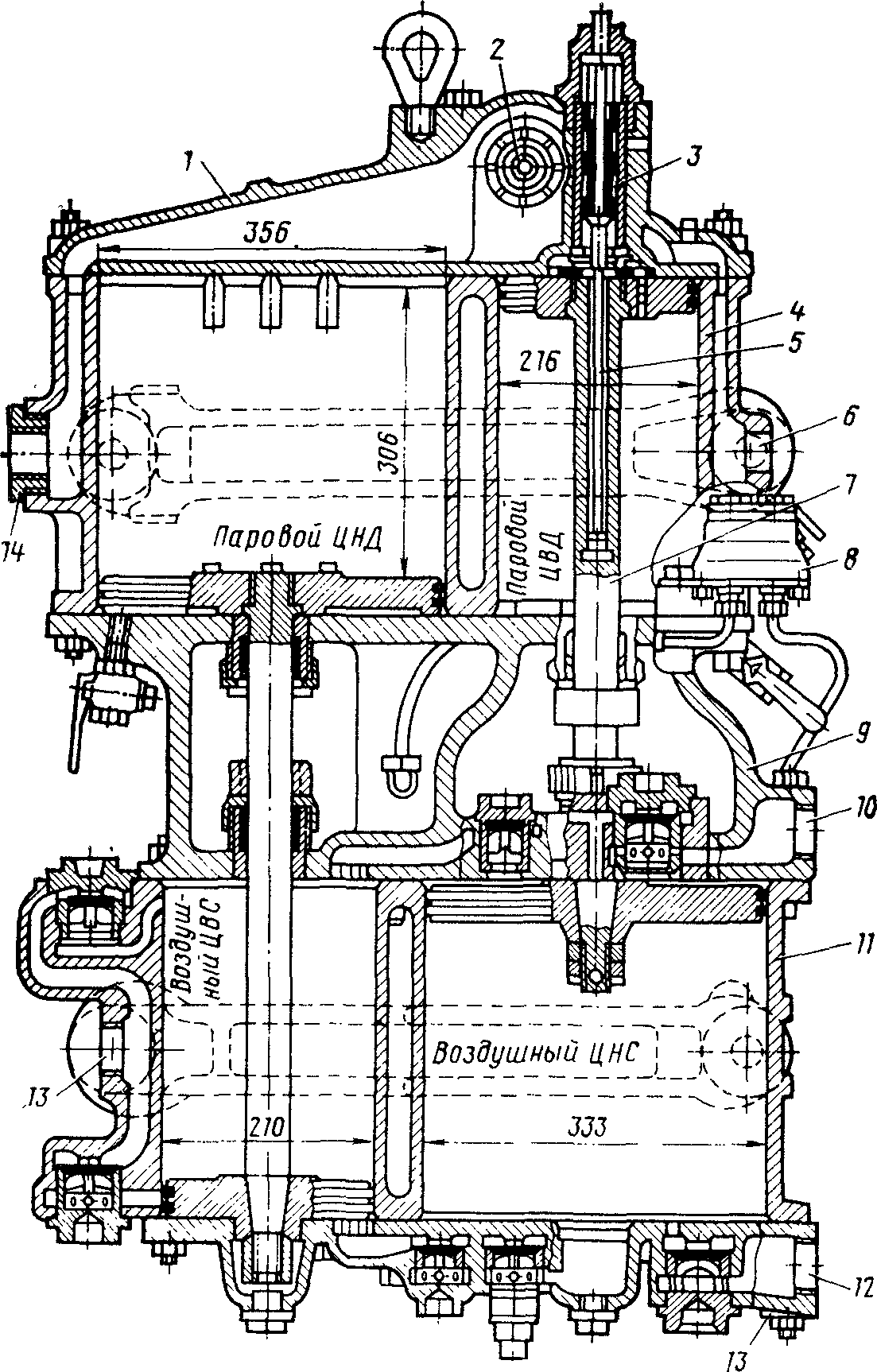
Fig. 3. Cross-compound pump 8.5 ″ -120D: 1 - cover; 2 - main spool; 3 - variable spool; 4 - block of steam cylinders; 5 - pusher of the variable spool; 6 - branch of the steam supply pipe; 7 - rod with pistons; 8 - automatic oiler; 9 - intermediate part with stem seals, bypass and suction valves; 10 - outlet to the suction filter; 11 - block of air cylinders with discharge valves; 12 - cover with bypass and suction valves; 13 - branch to the main tank; 14 - branch of the steam outlet pipe
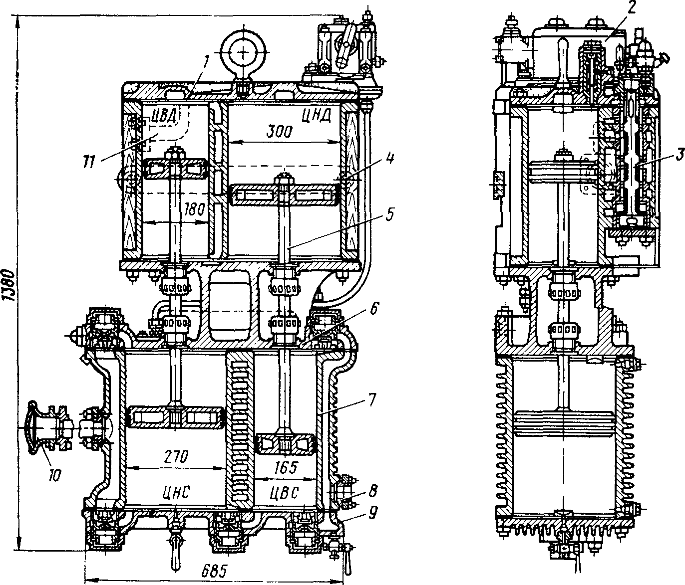
Fig. 4. Knorra compound pump, type P: 1 - cover with variable spool, 2 - grease nipple: 3 - main spool; 4 - block of steam cylinders; 5 - rod with pistons; 6 - intermediate part with oil seals and valves; 7 - block of air cylinders; 8 - branch to the main tank; 9 - cover with valves; 10 - suction filter; 11 - branch of the steam supply pipe Table 3. Dimensions of steam-air pumps
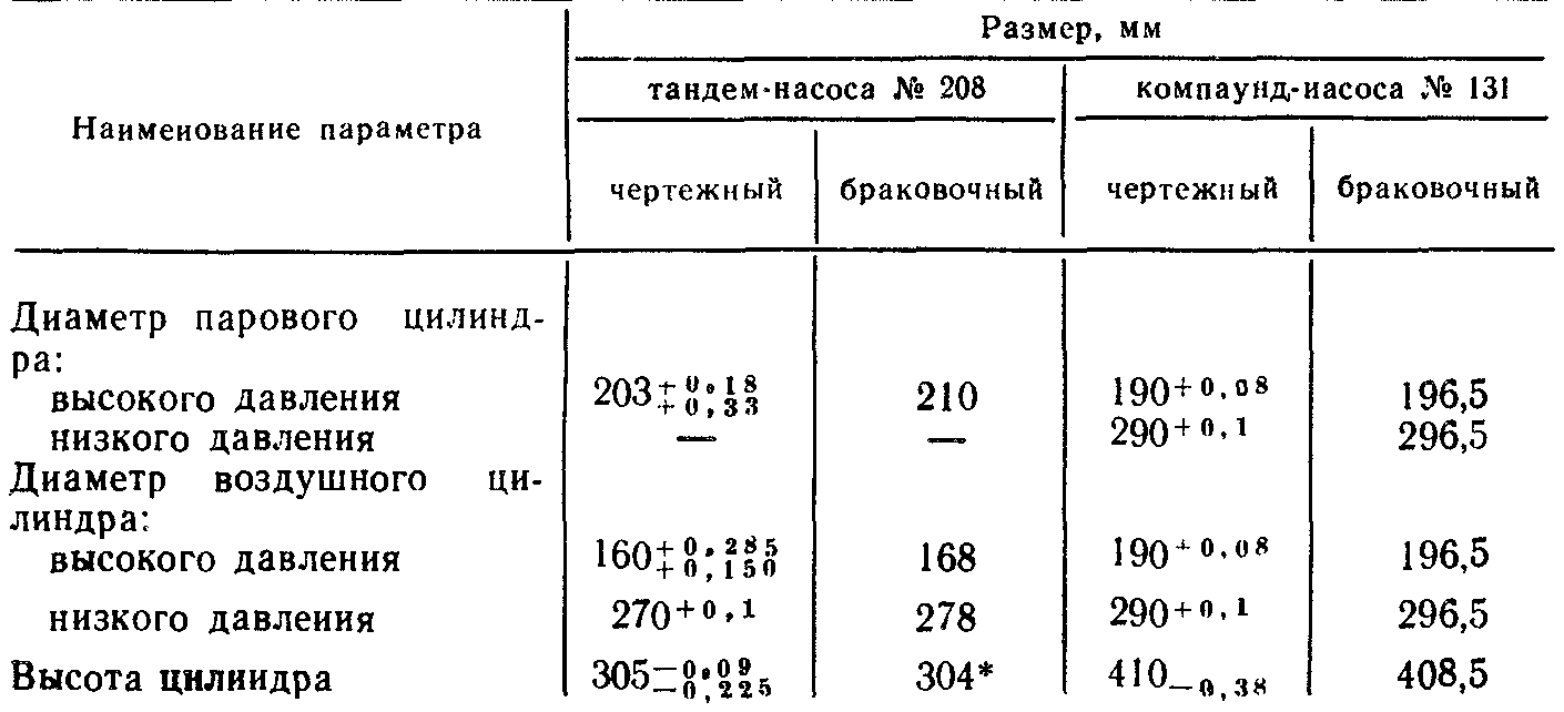
Continuation of table. 19
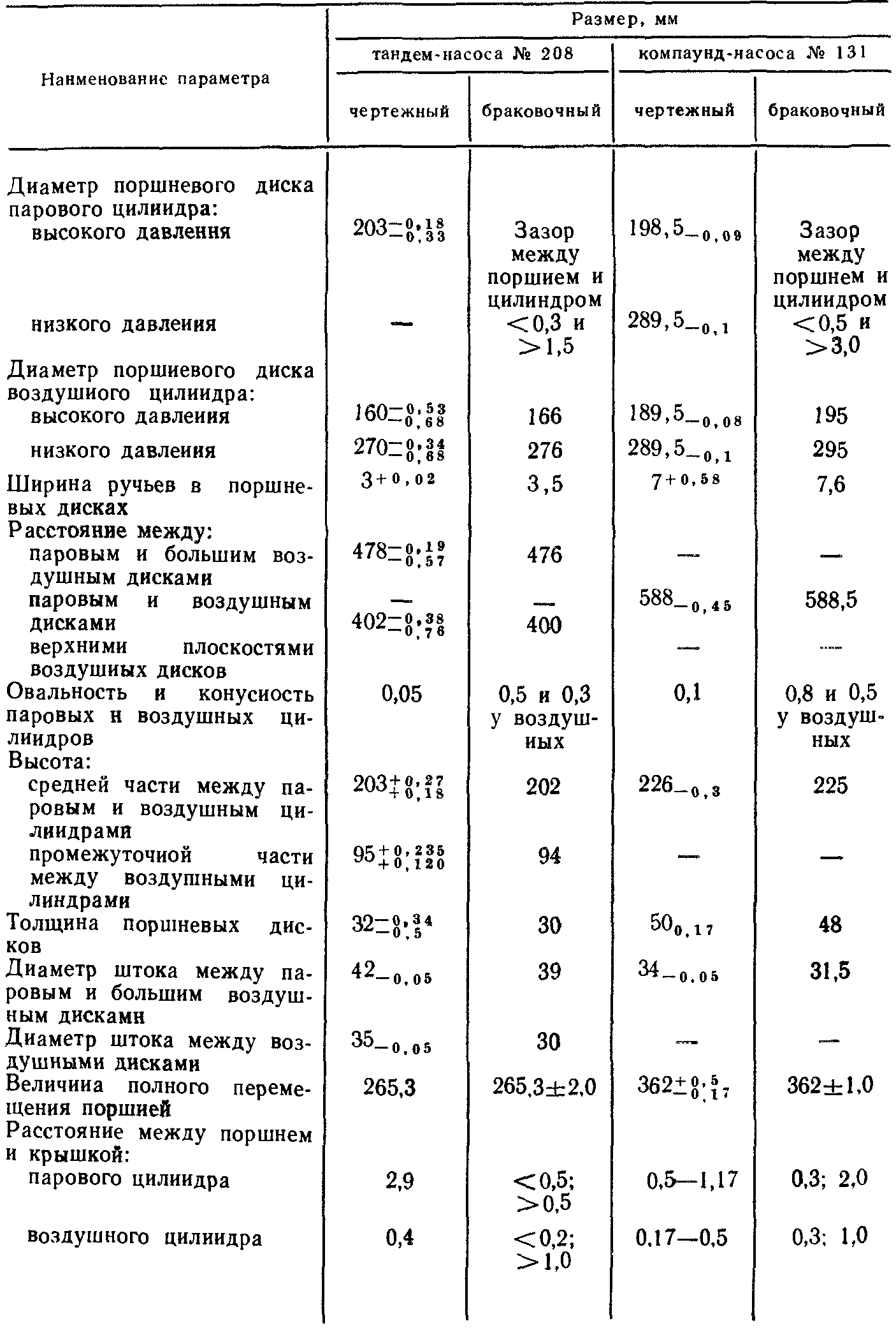
Table 3a. Graduation dimensions of the cylinders of the compound pump No. 131 * Limit size during repairs on class = "aligncenter" width = "1410" height = "1501" [/ img] Notes. 1. To press in the bushings, the inner diameter of the large steam and air pump cylinders is bored to size 308 + 0.05 mm, and the small one - 208 + 0.045 mm. The outer diameters of the bushings (for pressing) should be 308 + 0.1mm for large cylinders, 208 + 0.075 ΜΜ for small cylinders.The inner diameter of the bushings before boring should be 285 and 185 mm, respectively, and after boring have drawing dimensions.
Table 4. Dimensions of cylinders, pistons and rings of steam-air pumps
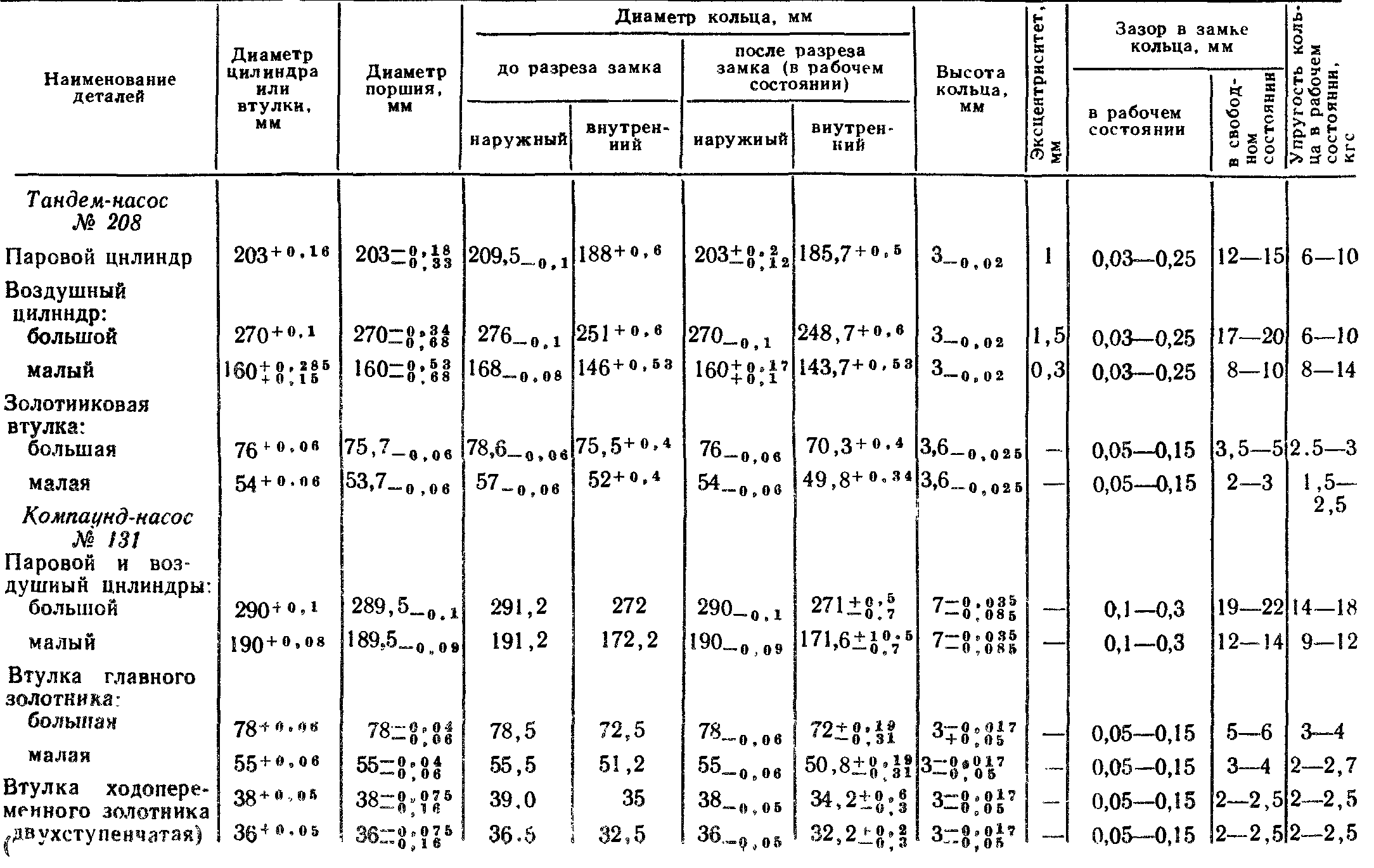
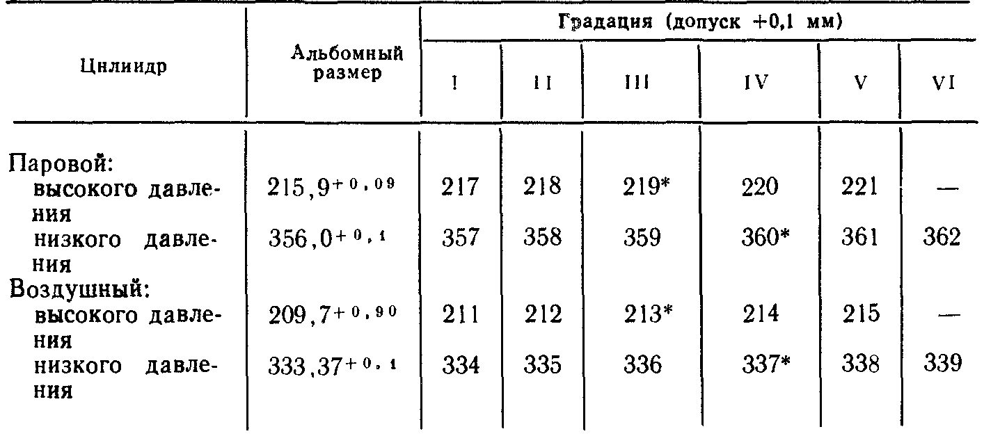
Table 5. Gradation dimensions for cylinder bore of compound pump No. 131, mm * Limit size during repair at the factory. Table 6. Graduated dimensions for boring cylinders of cross-compound pump 8U2 ″ -120D, mm
* Size limit for factory repair. Table 7. Norms of tolerances and wear of cross-compound pump parts 81/2 ″ -120D, mm
| Parameter name | Landscape size | Size allowed after repair | |
| depot | factory | ||
| Steam cylinder diameter: high pressure | 215,9 | 222,3 | 220,0 |
| low pressure | 355,6 | 363,6 | 362,0 |
| Air cylinder diameter: high pressure | 209,5 | 216,1 | 214,0 |
| low pressure | 333,37 | 341,1 | 339,0 |
| Cylinder length (steam and air) | 345,0 | 343,5 | 344,0 |
| Parameter name | Album | Size allowed after repair | |
| the size | depot | factory | |
| Spool bushing diameter (internal variable spool): in the upper spool cover | 37,69 | 40,9 | 39,0 |
| in the pump cover housing | 38,2 | 41,3 | 40,0 |
| Main spool inner sleeve diameter: large | 83,0 | 86,6 | 85,0 |
| small | 62,0 | 65,6 | 64,0 |
| Steam cylinder piston disc diameter: high pressure | 214,0 | 220,3 | 219,0 |
| low pressure | 352,0 | 361,0 | 361.0 |
| Air cylinder disc diameter: high pressure | 208,0 | 214,0 | 213,0 |
| low pressure | 331,0 | 339,0 | 336,0 |
Table 8. Time of filling the main tank with compound pump No. 131
| Steam pressure. kgf / cm2 | Time of filling the main tank with a volume of 1000 l from 2 to 8 kgf / cm2, s | Steam pressure, kgf / cm | Time of filling the main tank with a volume of 1000 l from 2 to 8 kgf / cm2, s |
| 10 | 130 | 13 | 115 |
| 11 | 125 | 14 | BY |
| 12 | 120 | 15 | 105 |
Note. At a steam pressure of 6 - 11 kgf / cm2, the time of filling the tank from 2 to 0.5 kgf / s and 2 is not more than 90 s Table 9. Dimensions of stroke regulators for pumps No. 279 and 91
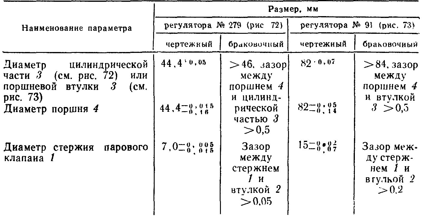
Fig. 5. Stroke regulator No. 270 for tandem pump: 1 - steam valve stem; 2 - guide rod 1; 3 - cylindrical part of the body; 4 - piston; 5 - diaphragm saddle; 6 - metal diaphragm
Fig. 6. Stroke regulator No. 91 of the compound pump: 1 - steam valve stem, 2 - stem sleeve, 3 - piston sleeve, 4 - piston; 5 diaphragm seat, 6 - diaphragm
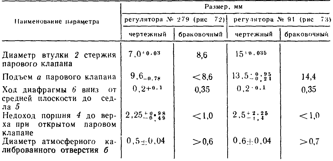
Table 10. Characteristics and installation location of lubricators
| Purpose and characteristics | Place of installation |
| Oiler No. 202 steam cylinder pump | |
| For lubricating the rubbing parts of the steam part of the steam-air pump. The volume of the oiler reservoir is 750 cm3, the calibrated hole is 0.4 mm in diameter. Lubricant consumption approx. 0.2 g for 60 double pump strokes | On the top cover of the steam cylinder of the tandem pump, on the steam supply pipe in front of the compound pump stroke regulator (not on all steam locomotives) |
| Automatic oiler No. 1053 | |
| For lubricating the rubbing parts of the air cylinders of pumps. The volume of the reservoir of the 85 cm3 oiler is designed for continuous operation of the pump for 5 - 6 hours. The gap between the rod and the sleeve in diameter is from 0.12 to 0.19 mm | On a bracket with a tube supply to the air HPC |
| Grease nipple No. M5 | |
| For automatic lubrication of rubbing parts of steam and air parts of pumps and oil seals with pneumatic drive from HPC. The capacity of the oil reservoir for lubricating the steam part is 1.4 liters, for the air part (three branches) - 2.75 liters. Maximum feed by each plunger for 100 revolutions of the eccentric shaft 32 cm3. Plunger diameter 8 mm, plunger stroke 8.2 mm, feed regulator stroke 0 to 5 mm (one revolution equals 1 mm) | There is a compound pump on the lid of the steam LPC. Lubricating pipes are led into the steam pipe up to the pump stroke regulator, to the variable spool, to the air LPC and to the oil seals (two) |
Table 11. Standards of tolerances and wear of parts of automatic oiler No. 1053, mm
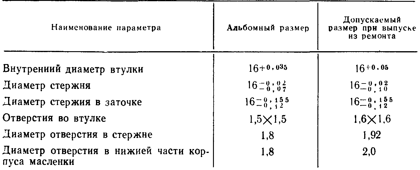
Table 12. List of pump and regulator parts to be checked during flushing repair of steam locomotives
| Part name (device) | Parts to be inspected | What is checked |
| Tandem pump No. 208 | Tandem pump brackets | Fastening the pump to the bracket |
| Multi-piston valve | O-ring condition | |
| Variable spool rod | General condition - wear at spool and tile mating points | |
| Variable piston valve and variable spool bushings | Condition of bushings | |
| Spool tiles | Fastening tiles to disc, wear | |
| Steam disc and stem | Fastening the disc to the stem. Vertical channel in the stock | |
| Suction and discharge valves | Seat condition, lapping and valve lift | |
| Flange gaskets | General state | |
| Automatic and steam lubricators | Calibrated holes in fittings No oil leakage in connections | |
| Compauid pump No. 131 | Main and variable speed spools | O-ring condition |
| Main spool and variable speed valve bushing Suction, discharge and relief valves | General condition Condition of valve plates, seats and springs |
| Part name (device) | Parts to be inspected | What is checked |
| Flange gaskets Oil seals | Are there any damages on the gaskets? Fastening the nuts? Are there any gaps in the joints and along the stem? | |
| Grease nipple No. M-5 | Oiler and its drive | Drive operation (lubricant supply) and feed adjustment |
| Regulators for pumps No. 279 and 91 | Regulator diaphragms | The condition of the diaphragm, whether there are cracks or residual deflection |
| Steam valve | Steam valve. Steam pipe fixing points | The condition of the lapping surface of the valve, its seat, connections and attachment points |
| Maximum pressure valves | Valves No. 3MD and 3MDA | Adjustment for the pressure in the brake cylinders 3.8 -
|
| Air lines and other braking equipment | Air ducts, connecting hoses, brake valves (filters, oil separators, dust traps, etc.) | The tightness of the connections, fasteners, the correctness of the adjustment, the serviceability of the operation, the presence of seals or tags about the repair performed |