Here you will find out:
- Calculation of an air heating system - a simple technique
- The main method for calculating the air heating system
- An example of calculating heat loss at home
- Calculation of air in the system
- Air heater selection
- Calculation of the number of ventilation grilles
- Aerodynamic system design
- Additional equipment increasing the efficiency of air heating systems
- Application of thermal air curtains
Such heating systems are divided according to the following criteria: By type of energy carrier: systems with steam, water, gas or electric heaters. By the nature of the flow of the heated coolant: mechanical (with the help of fans or blowers) and natural impulse. By the type of ventilation schemes in heated rooms: direct-flow, or with partial or full recirculation.
By determining the place of heating the coolant: local (the air mass is heated by local heating units) and central (heating is carried out in a common centralized unit and subsequently transported to the heated buildings and premises).
Calculation of an air heating system - a simple technique
Air heating design is not an easy task. To solve it, it is necessary to find out a number of factors, the independent determination of which may be difficult. RSV specialists can make for you a preliminary project for air heating of a room based on GRERES equipment free of charge.
An air heating system, like any other, cannot be created at random. To ensure the medical norm of temperature and fresh air in the room, a set of equipment will be required, the choice of which is based on an accurate calculation. There are several methods for calculating air heating, of varying degrees of complexity and accuracy. The usual problem with calculations of this type is that the influence of subtle effects is not taken into account, which is not always possible to foresee.
Therefore, making an independent calculation without being a specialist in the field of heating and ventilation is fraught with errors or miscalculations. However, you can choose the most affordable method based on the choice of the power of the heating system.
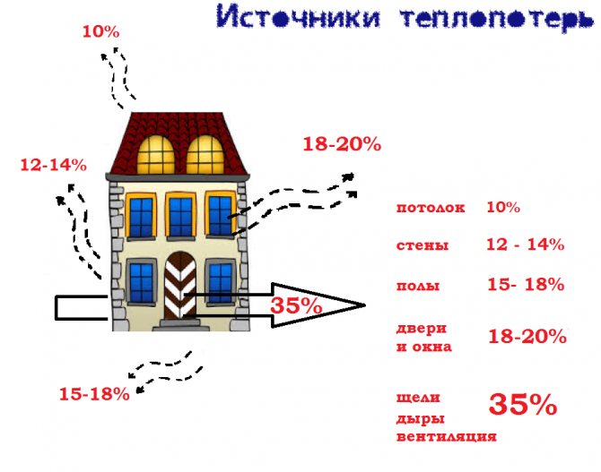
The meaning of this technique is that the power of heating devices, regardless of their type, must compensate for the heat loss of the building. Thus, having found the heat loss, we obtain the value of the heating power, according to which a specific device can be selected.
The formula for determining heat loss:
Q = S * T / R
Where:
- Q - value of heat loss (W)
- S - the area of all structures of the building (room)
- T - the difference between internal and external temperatures
- R - thermal resistance of the enclosing structures
Example:
A building with an area of 800 m2 (20 × 40 m), 5 m high, there are 10 windows measuring 1.5 × 2 m.We find the area of structures: 800 + 800 = 1600 m2 (floor and ceiling area) 1.5 × 2 × 10 = 30 m2 (window area) (20 + 40) × 2 × 5 = 600 m2 (wall area). Subtract the area of the windows from here, we get a "clean" wall area of 570 m2
In the SNiP tables, we find the thermal resistance of concrete walls, floors and floors and windows. You can determine it yourself using the formula:
Where:
- R - thermal resistance
- D - material thickness
- K - coefficient of thermal conductivity
For simplicity, we will take the thickness of the walls and floor with the ceiling to be the same, equal to 20 cm.Then the thermal resistance will be equal to 0.2 m / 1.3 = 0.15 (m2 * K) / W We will choose the thermal resistance of the windows from the tables: R = 0, 4 (m2 * K) / W The temperature difference is taken as 20 ° C (20 ° C inside and 0 ° C outside).
Then for the walls we get
- 2150 m2 × 20 ° C / 0.15 = 286666 = 286 kW
- For windows: 30 m2 × 20 ° C / 0.4 = 1500 = 1.5 kW.
- Total heat loss: 286 + 1.5 = 297.5 kW.
This is the amount of heat loss that must be compensated for with air heating with a capacity of about 300 kW.
It is noteworthy that when using floor and wall insulation, heat loss is reduced by at least an order of magnitude.
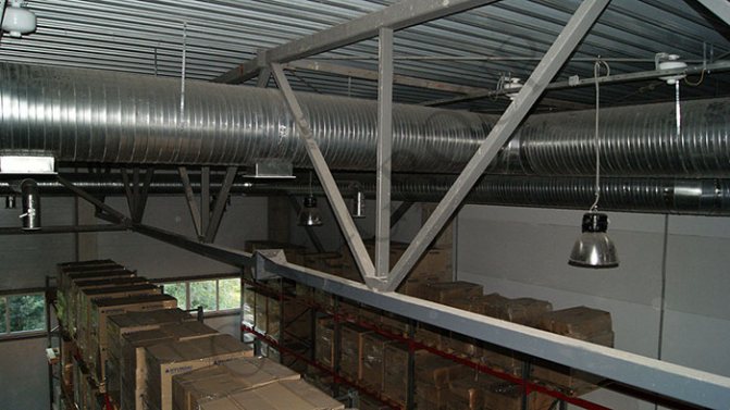
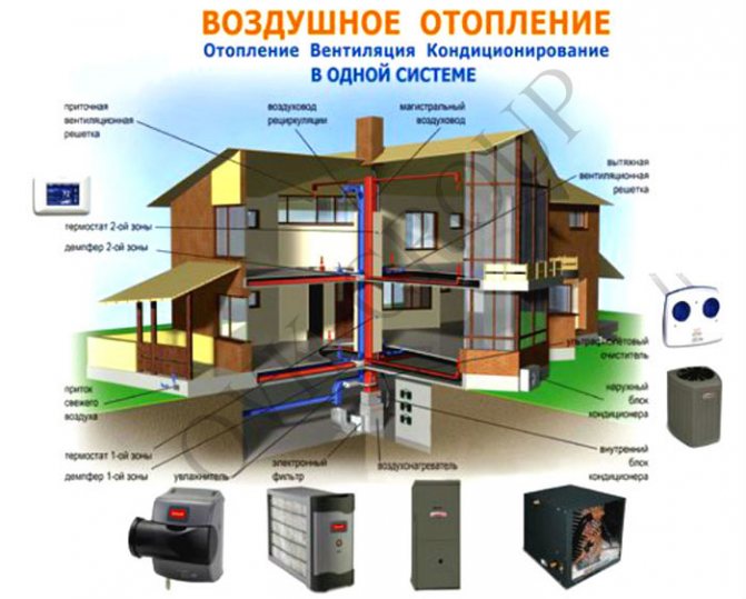
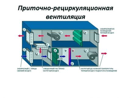
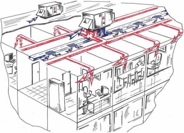
Supply ventilation combined with air heating
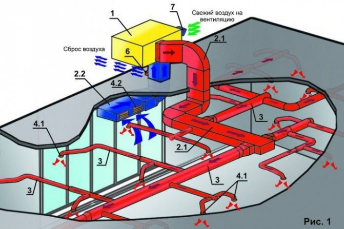
The principle of air heating based on an air supply unit is based on air recirculation, the unit takes air from the room, adds the required amount of fresh air, cleans, heats up and re-supplies the room. To distribute air throughout the rooms, a network of air ducts is laid, ending with air distribution grilles, diffusers or anemostats. The main difficulty of such systems, according to specialists of our design institute for heating in Ukraine, is the balancing of such systems, the more rooms there are, the harder it is to link them together. This requires expensive automation, so such systems are more effective in the industrial and manufacturing sectors, in large stores and other premises with a large volume.
Design of air heating systems based on air supply units
The design of heating systems, including air ones, begins with a heat engineering calculation, which determines the required amount of heat for each production or household premises. After calculating the required heat, we set the supply temperature, depending on:
- Room heights - the higher the room height, the lower the supply temperature so that the air jet reaches the floor.
- Materials of air ducts and distribution grilles - plastic grilles tend to deform even from a not very high temperature, which lasts for a long time.
- Purpose of the room - in rooms with a constant presence of people near the air diffusers, it is necessary to reduce the flow temperature, otherwise discomfort will arise.
The main point of determining the supply temperature is to determine the air flow rate, the higher the temperature difference between the room air and the supply air, the less air volume is required. After determining the required temperature, calculations are carried out according to the j-d diagram to determine the temperature of the coolant. Unlike a water heating project, an air project contains a distribution diagram not of pipes, but of air ducts, the diameters of which are calculated and signed on sheets of project documentation.
Air heating project for home and production
In the finished project of the air heating system, regardless of the purpose of the premises, all the data required for the implementation of the project are always indicated, the set of project documentation includes not only plans with the layout of the air ducts printed on them, but also many other data. Any project necessarily contains brief information about the system, the final figures for heat and power consumption, technical characteristics of the equipment proposed by the project and a brief description of the system. In addition to a brief description, a more detailed description in the explanatory note to the project must be attached. In addition, the project of air heating and ventilation of a production workshop or a cottage contains an axonometric diagram of the air duct wiring system, on which the marks of the heights of the passage of air ducts and the location of equipment are marked.
Also attached to the project is the specification of the main equipment and all materials required for installation, according to this information, not only we, but also any other installation organization will be able to perform installation work. Thus, the design of the air heating system contains all the necessary information, and complex nodes of the passage, the location of equipment, ventilation chambers and the composition of the air supply unit are also placed on the corresponding sheets, if necessary.
The main method for calculating the air heating system
The basic principle of operation of any SVO is to transfer thermal energy through the air by cooling the coolant. Its main elements are a heat generator and a heat pipe.
Air is supplied to the room already heated to the temperature tr in order to maintain the desired temperature tv. Therefore, the amount of accumulated energy should be equal to the total heat loss of the building, i.e. Q. The equality takes place:
Q = Eot × c × (tv - tn)
In the formula E is the flow rate of heated air kg / s for heating the room. From equality we can express Eot:
Eot = Q / (c × (tv - tn))
Recall that the heat capacity of air c = 1005 J / (kg × K).
According to the formula, only the amount of supplied air is determined, which is used only for heating only in recirculation systems (hereinafter referred to as RSCO).
In supply and recirculation systems, part of the air is taken from the street, and the other part is taken from the room. Both parts are mixed and, after heating to the required temperature, are delivered to the room.
If CBO is used as ventilation, then the amount of air supplied is calculated as follows:
- If the amount of air for heating exceeds the amount of air for ventilation or is equal to it, then the amount of air for heating is taken into account, and the system is chosen as a direct-flow system (hereinafter referred to as PSVO) or with partial recirculation (hereinafter referred to as CRSVO).
- If the amount of air for heating is less than the amount of air required for ventilation, then only the amount of air required for ventilation is taken into account, the PSVO is introduced (sometimes - RSPO), and the temperature of the supplied air is calculated by the formula: tr = tv + Q / c × Event ...
If the tr value exceeds the permissible parameters, the amount of air introduced through the ventilation should be increased.
If there are sources of constant heat generation in the room, then the temperature of the supplied air is reduced.

The included electrical appliances generate about 1% of the heat in the room. If one or more devices will work continuously, their thermal power must be taken into account in the calculations.
For a given room, the tr value may differ. It is technically possible to implement the idea of supplying different temperatures to separate rooms, but it is much easier to supply air of the same temperature to all rooms.
In this case, the total temperature tr is taken the one that turned out to be the smallest. Then the amount of supplied air is calculated using the formula that determines Eot.
Next, we determine the formula for calculating the volume of incoming air Vot at its heating temperature tr:
Vot = Eot / pr
The answer is recorded in m3 / h.
However, the air exchange in the room Vp will differ from the Vot value, since it must be determined based on the internal temperature tv:
Vot = Eot / pv
In the formula for determining Vp and Vot, the air density values pr and pv (kg / m3) are calculated taking into account the heated air temperature tr and the room temperature tv.
The room supply temperature tr must be higher than tv. This will reduce the amount of air supplied and will reduce the size of the channels of systems with natural air movement or reduce electricity costs if mechanical induction is used to circulate the heated air mass.
Traditionally, the maximum temperature of the air entering the room when it is supplied at a height exceeding 3.5 m should be 70 ° C. If the air is supplied at a height of less than 3.5 m, then its temperature is usually equal to 45 ° C.
For residential premises with a height of 2.5 m, the permissible temperature limit is 60 ° C. If the temperature is set higher, the atmosphere loses its properties and is not suitable for inhalation.
If the air-thermal curtains are located at the outer gates and openings that go outside, then the temperature of the incoming air is 70 ° C, for curtains in the outer doors, up to 50 ° C.
The supplied temperatures are influenced by the methods of air supply, the direction of the jet (vertically, inclined, horizontally, etc.). If people are constantly in the room, then the temperature of the supplied air should be reduced to 25 ° C.
After performing preliminary calculations, you can determine the required heat consumption for heating the air.
For RSPO, heat costs Q1 are calculated by the expression:
Q1 = Eot × (tr - tv) × c
For PSVO, Q2 is calculated according to the formula:
Q2 = Event × (tr - tv) × c
The heat consumption Q3 for RRSVO is found by the equation:
Q3 = × c
In all three expressions:
- Eot and Event - air consumption in kg / s for heating (Eot) and ventilation (Event);
- tn - outdoor temperature in ° С.
The rest of the characteristics of the variables are the same.
In the CRSVO, the amount of recirculated air is determined by the formula:
Erec = Eot - Event
The variable Eot expresses the amount of mixed air heated to a temperature tr.
There is a peculiarity in the PSVO with natural motivation - the amount of moving air changes depending on the outside temperature. If the outside temperature drops, the system pressure rises. This leads to an increase in the amount of air entering the house. If the temperature rises, then the opposite process occurs.
Also, in SVO, in contrast to ventilation systems, air moves with a lower and varying density compared to the density of the air surrounding the air ducts.
Because of this phenomenon, the following processes occur:
- Coming from the generator, the air passing through the air ducts is noticeably cooled during movement
- With natural movement, the amount of air entering the room changes during the heating season.
The above processes are not taken into account if fans are used in the air circulation system for air circulation; it also has a limited length and height.
If the system has many ramifications, rather long, and the building is large and tall, then it is necessary to reduce the process of cooling the air in the ducts, to reduce the redistribution of air supplied under the influence of natural circulating pressure.

When calculating the required power of extended and branched air heating systems, it is necessary to take into account not only the natural process of cooling the air mass while moving through the duct, but also the effect of the natural pressure of the air mass when passing through the channel
To control the air cooling process, a thermal calculation of the air ducts is performed. To do this, it is necessary to set the initial air temperature and clarify its flow rate using formulas.
To calculate the heat flux Qohl through the walls of the duct, the length of which is l, use the formula:
Qohl = q1 × l
In the expression, the q1 value denotes the heat flux passing through the walls of an air duct with a length of 1 m. The parameter is calculated by the expression:
q1 = k × S1 × (tsr - tv) = (tsr - tv) / D1
In the equation, D1 is the resistance of heat transfer from heated air with an average temperature tsr through the area S1 of the walls of an air duct with a length of 1 m in a room at a temperature of tv.
The heat balance equation looks like this:
q1l = Eot × c × (tnach - tr)
In the formula:
- Eot is the amount of air required to heat the room, kg / h;
- c - specific heat capacity of air, kJ / (kg ° С);
- tnac - air temperature at the beginning of the duct, ° С;
- tr is the temperature of the air discharged into the room, ° С.
The heat balance equation allows you to set the initial air temperature in the duct at a given final temperature and, conversely, find out the final temperature at a given initial temperature, as well as determine the air flow rate.
The temperature tnach can also be found using the formula:
tnach = tv + ((Q + (1 - η) × Qohl)) × (tr - tv)
Here η is the part of Qohl entering the room; in the calculations, it is taken equal to zero. The characteristics of the remaining variables were mentioned above.
The refined hot air flow rate formula will look like this:
Eot = (Q + (1 - η) × Qohl) / (c × (tsr - tv))
Let's move on to an example of calculating air heating for a specific house.
Norms of temperature regimes of premises
Before carrying out any calculations of the parameters of the system, it is necessary, at a minimum, to know the order of the expected results, as well as to have available standardized characteristics of some tabular values that must be substituted in the formulas or be guided by them.
Having performed calculations of parameters with such constants, one can be sure of the reliability of the sought dynamic or constant parameter of the system.
For premises for various purposes, there are reference standards for the temperature regimes of residential and non-residential premises. These norms are enshrined in the so-called GOSTs.
For a heating system, one of these global parameters is the room temperature, which must be constant regardless of the season and ambient conditions.
According to the regulation of sanitary standards and rules, there are differences in temperature relative to the summer and winter seasons. The air conditioning system is responsible for the temperature regime of the room in the summer season, the principle of its calculation is detailed in this article.
But the room temperature in winter is provided by the heating system. Therefore, we are interested in the temperature ranges and their tolerances for the deviations for the winter season.
Most regulatory documents stipulate the following temperature ranges that allow a person to be comfortable in a room.
For non-residential premises of an office type with an area of up to 100 m2:
- 22-24 ° С - optimal air temperature;
- 1 ° С - permissible fluctuation.
For office-type premises with an area of more than 100 m2, the temperature is 21-23 ° C. For non-residential premises of an industrial type, the temperature ranges differ greatly depending on the purpose of the premises and the established labor protection standards.

Each person has their own comfortable room temperature. Someone likes it to be very warm in the room, someone is comfortable when the room is cool - this is all quite individual
As for residential premises: apartments, private houses, estates, etc., there are certain temperature ranges that can be adjusted depending on the wishes of the residents.
And yet, for specific premises of an apartment and a house, we have:
- 20-22 ° С - living room, including children's room, tolerance ± 2 ° С -
- 19-21 ° С - kitchen, toilet, tolerance ± 2 ° С;
- 24-26 ° С - bathroom, shower room, pool, tolerance ± 1 ° С;
- 16-18 ° С - corridors, hallways, staircases, storerooms, tolerance 3 ° С
It is important to note that there are several more basic parameters that affect the temperature in the room and which you need to focus on when calculating the heating system: humidity (40-60%), the concentration of oxygen and carbon dioxide in the air (250: 1), the speed of movement of air mass (0.13-0.25 m / s), etc.
An example of calculating heat loss at home
The house in question is located in the city of Kostroma, where the temperature outside the window in the coldest five-day period reaches -31 degrees, the ground temperature is + 5 ° C. The desired room temperature is + 22 ° C.
We will consider a house with the following dimensions:
- width - 6.78 m;
- length - 8.04 m;
- height - 2.8 m.
The values will be used to calculate the area of the enclosing elements.
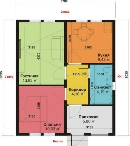
For calculations, it is most convenient to draw a house plan on paper, indicating on it the width, length, height of the building, the location of windows and doors, their dimensions
The walls of the building consist of:
- aerated concrete with a thickness of B = 0.21 m, thermal conductivity coefficient k = 2.87;
- foam B = 0.05 m, k = 1.678;
- facing brick В = 0.09 m, k = 2.26.
When determining k, information from tables should be used, or better - information from a technical passport, since the composition of materials from different manufacturers may differ, therefore, have different characteristics.
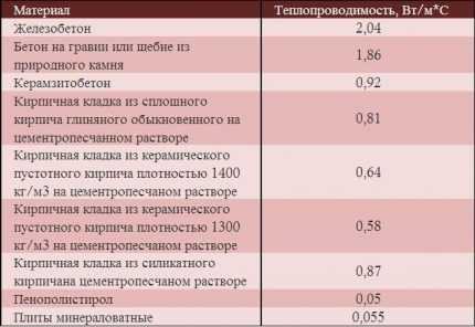
Reinforced concrete has the highest thermal conductivity, mineral wool slabs - the lowest, so they are most effectively used in the construction of warm houses
The floor of the house consists of the following layers:
- sand, B = 0.10 m, k = 0.58;
- crushed stone, B = 0.10 m, k = 0.13;
- concrete, B = 0.20 m, k = 1.1;
- ecowool insulation, B = 0.20 m, k = 0.043;
- reinforced screed, B = 0.30 m k = 0.93.
In the above plan of the house, the floor has the same structure throughout the entire area, there is no basement.
The ceiling consists of:
- mineral wool, B = 0.10 m, k = 0.05;
- drywall, B = 0.025 m, k = 0.21;
- pine shields, B = 0.05 m, k = 0.35.
The ceiling has no exits to the attic.
There are only 8 windows in the house, all of them are two-chambered with K-glass, argon, D = 0.6. Six windows have dimensions of 1.2x1.5 m, one is 1.2x2 m, and one is 0.3x0.5 m. The doors have dimensions of 1x2.2 m, the D index according to the passport is 0.36.
Calculation of the number of ventilation grilles
The number of ventilation grilles and the air velocity in the duct are calculated:
1) We set the number of lattices and choose their sizes from the catalog
2) Knowing their number and air consumption, we calculate the amount of air for 1 grill
3) We calculate the speed of air exit from the air distributor according to the formula V = q / S, where q is the amount of air per grille, and S is the area of the air distributor. It is imperative that you familiarize yourself with the standard outflow rate, and only after the calculated speed is less than the standard one can it be considered that the number of gratings is selected correctly.
Second phase
2. Knowing the heat loss, we calculate the air flow in the system using the formula
G = Qп / (с * (tg-tv))
G- mass air flow, kg / s
Qp - heat loss of the room, J / s
C- heat capacity of air, taken as 1.005 kJ / kgK
tg - temperature of heated air (inflow), K
tv - air temperature in the room, K
We remind you that K = 273 ° C, that is, to convert your Celsius degrees to Kelvin degrees, you need to add 273 to them. And to convert kg / s to kg / h, you need to multiply kg / s by 3600.
Read next: Artificial stone sink pros and cons
Before calculating the air flow, it is necessary to find out the air exchange rates for a given type of building. The maximum supply air temperature is 60 ° C, but if the air is supplied at a height of less than 3 m from the floor, this temperature drops to 45 ° C.
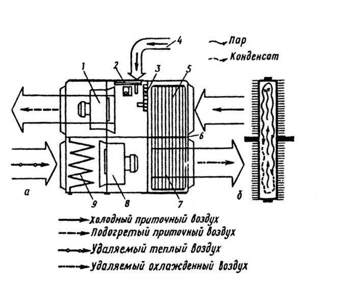
Still another, when designing an air heating system, it is possible to use some energy saving means, such as recuperation or recirculation. When calculating the amount of air in a system with such conditions, you need to be able to use the moist air id diagram.
Aerodynamic system design
5. We do the aerodynamic calculation of the system. To facilitate the calculation, experts advise to roughly determine the cross-section of the main duct for the total air flow:
- flow rate 850 m3 / hour - size 200 x 400 mm
- Flow rate 1000 m3 / h - size 200 x 450 mm
- Flow rate 1 100 m3 / h - size 200 x 500 mm
- Flow rate 1 200 m3 / hour - size 250 x 450 mm
- Flow rate 1 350 m3 / h - size 250 x 500 mm
- Flow rate 1 500 m3 / h - size 250 x 550 mm
- Flow rate 1 650 m3 / h - size 300 x 500 mm
- Flow rate 1 800 m3 / h - size 300 x 550 mm
How to choose the right air ducts for air heating?
Summarizing
Designing a ventilation system may seem simple only at first glance - lay a couple of pipes and bring them to the roof. In fact, everything is much more complicated, and in the case when ventilation is combined with air heating, the complexity of the task only increases, because it is necessary to ensure not only the removal of dirty air, but also to achieve a stable temperature in the rooms.
The video in this article is theoretical in nature, in which experts provide answers to a number of common questions.
Did you like the article? Subscribe to our channel Yandex.Zen
Additional equipment increasing the efficiency of air heating systems
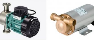
For the reliable operation of this heating system, it is necessary to provide for the installation of a backup fan or to mount at least two heating units per room.
If the main fan fails, the room temperature may drop below normal, but not more than 5 degrees, provided the outside air is supplied.
The temperature of the air flow supplied to the premises must be at least twenty percent lower than the critical temperature of autoignition of gases and aerosols present in the building.
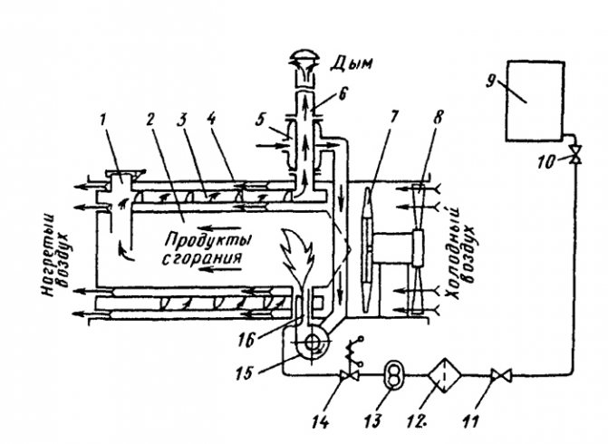
For heating the coolant in air heating systems, heating units of various types of structures are used.
With their help, heating units or ventilation supply chambers can also be completed.
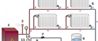
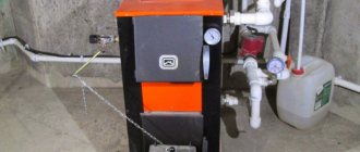
House air heating scheme. Click to enlarge.
In such heaters, the air masses are heated by the energy taken from the coolant (steam, water or flue gases), and they can also be heated by electric power plants.
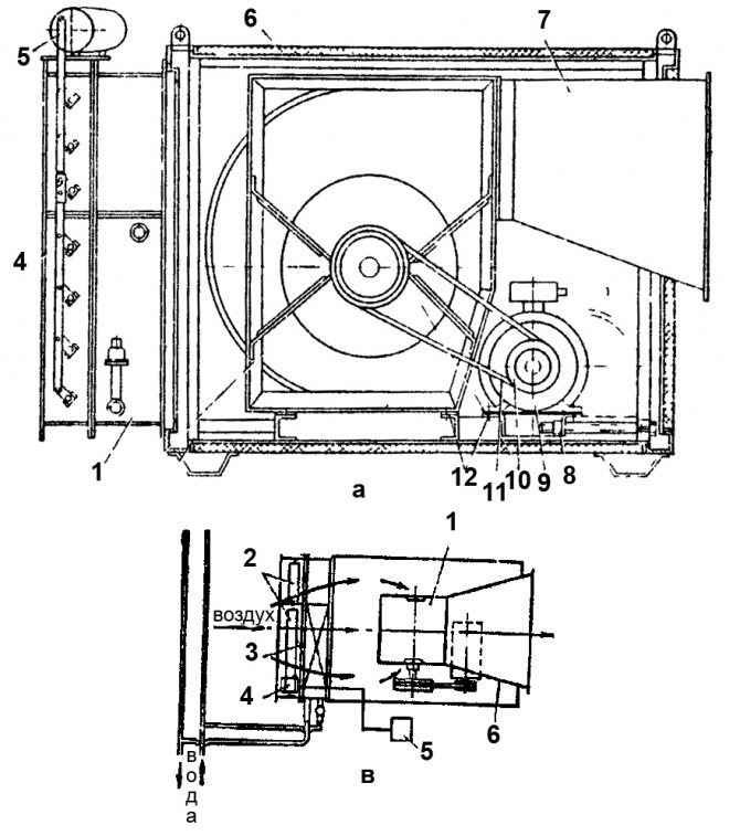
Heating units can be used to heat recirculated air.
They consist of a fan and a heater, as well as an apparatus that forms and directs the flow of the coolant supplied to the room.
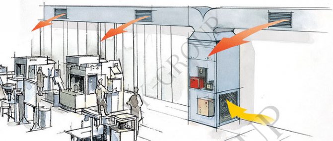
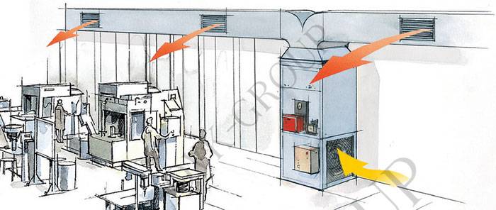
Large heating units are used to heat large production or industrial premises (for example, in wagon assembly shops), in which sanitary and hygienic and technological requirements allow the possibility of air recirculation.
Also, large heating air systems are used after hours for standby heating.
Classification of air heating systems
Such heating systems are divided according to the following criteria:
By type of energy carrier: systems with steam, water, gas or electric heaters.
By the nature of the flow of the heated coolant: mechanical (with the help of fans or blowers) and natural impulse.
By the type of ventilation schemes in heated rooms: direct-flow, or with partial or full recirculation.
By determining the place of heating the coolant: local (the air mass is heated by local heating units) and central (heating is carried out in a common centralized unit and subsequently transported to the heated buildings and premises).