In heating systems, where heaters and coolers are used in the piping nodes, there is a characteristic type of fittings - a two-way valve. The device quickly and accurately regulates the volumes of water supply and withdrawal. It is in demand in heating, ventilation and air conditioning systems. Nowadays, two-way valves equipped with an electric actuator, which are controlled by special sensors, are in great demand. These are reliable and easy-to-install devices, the design features and differences of which we will learn below.
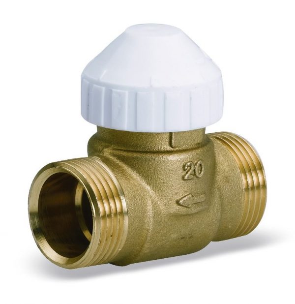
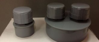
Two way valve
Purpose and design
The classic equipment of the device is as follows:
- thermostatic valve;
- thermal head with a remote sensor;
- thermal head valve;
- limiting sensor taking into account temperature;
- meter;
- circulation pump;
- water filter;
- check valve.
Two-way adjusting devices are used everywhere, but much depends on what material they are made of. Considering the design features, we will immediately make a reservation that valves are available with one or two seats. Using the second type, the flows of the working medium are regulated and shut off, and significant pressure drops are allowed, which a single-seat valve cannot cope with. The valve itself looks like a separate part with a mechanical or electronic drive. It happens that an additional source of energy is not provided, therefore it is installed after the installation of the device.
Advantages of a two-way valve:
- simple construction;
- easy to install;
- does not require human involvement for effective work;
- maintainable;
- reliable;
- serves for a long time;
- sealed;
- characterized by low hydraulic resistance;
- available.
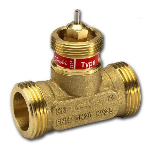
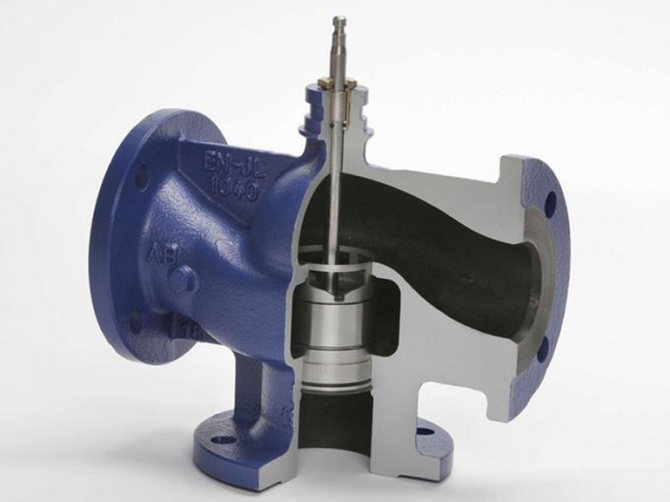
Paying attention to the design of the element, it seems that it is similar to a standard valve, but the mechanisms are significantly different. For example, the main plug of a valve is a stem or ball. That is, the stem, which is in a horizontal or vertical position, or a ball rotated around its axis by 90 degrees, is responsible for limiting the flow of water. The device works according to a simple scheme - a special hole opens and liquid is transported through it. In order for these structural elements to function, an actuator is connected to the valve, which requires electricity or compressed air. The drive itself is combined with separate devices that take into account system pressure, temperature and other characteristics.
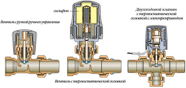
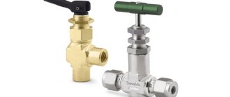
Valve design
Scope of application of two-way valves
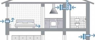
Two-way control valves are installed at individual and central heating points. In addition to heat supply, valves are also used:
- in water supply networks;
- in air conditioning and supply ventilation systems;
- in technological pipelines of oil refineries, food, petrochemical and chemical enterprises.
The working medium for the valves can be water, steam, oil fractions, oil products and other liquids and gases.
Areas of use
As noted above, this type of control valve is used in heating, ventilation and air conditioning systems. Consider separately the features of its use in a circuit with a "warm floor".
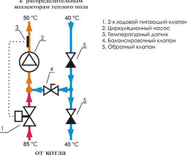
If a boiler is installed in the house, then its task is to heat the water and, as a rule, its temperature is quite high, suitable for radiators (from +75 to +95 degrees Celsius).For the "warm floor" system, such heating is not needed, since sanitary standards regulate a maximum of +35 degrees Celsius. This figure is enough to walk comfortably on the floor. If the temperature is higher, this will not only cause inconvenience to residents, but also negatively affect the finish floor covering. For example, linoleum or laminate flooring is easily deformed.
"Warm floor" is mounted under the screed, besides, different flooring materials are used. For this, the coolant is heated to +50 degrees Celsius. When underfloor heating is directly connected to a boiler or centralized heating system, the resulting temperature is too high. To lower it at the entrance to the circuit, a mixing valve for a warm floor is mounted, with a two-way or three-way valve already provided. As the name suggests, the purpose of such fittings is to mix hot and cold water circulating along the circuit. That is, the process of fluid passage changes - for the radiator, the water remains hot, and the already mixed, having a lower temperature, enters the warm floor.
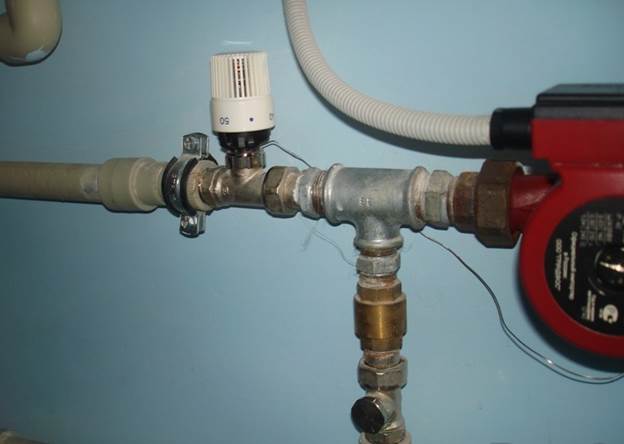
Installed valve
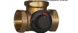
Types of three-way valves and features of their work
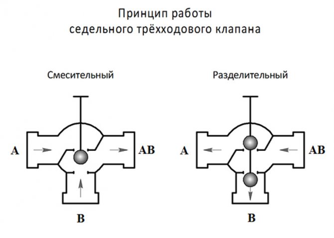
First of all, three-way thermal valves are classified according to their purpose into separation and mixing:
- At the mixing valve, 2 directions work to supply a heat carrier of different temperatures (hot and cold), and 1 direction outputs an already mixed fluid flow. The setting of the required temperature parameters is carried out by adjusting the temperature and proportions of the supplied flows.
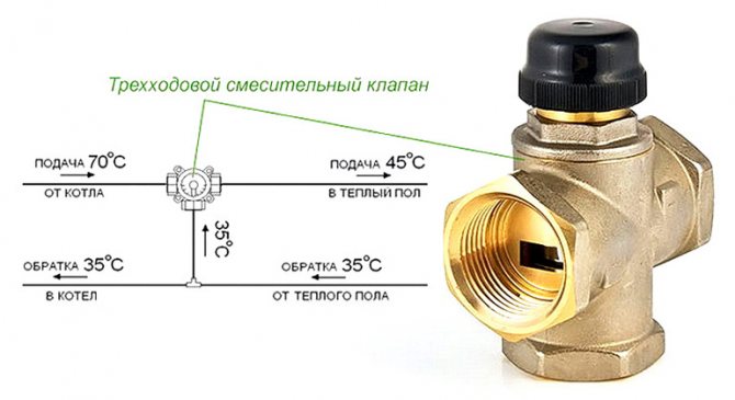
- At the distribution thermovalve, 1 branch pipe supplies the coolant, and the other 2 divide it among themselves and distribute it in different directions.
For your information! Under certain conditions, the 3-way mixing valve can operate in distribution mode.
According to the control method, three-way thermal valves are autonomous, manual, thermostatic and electric. The last two, as a rule, work in automatic mode.
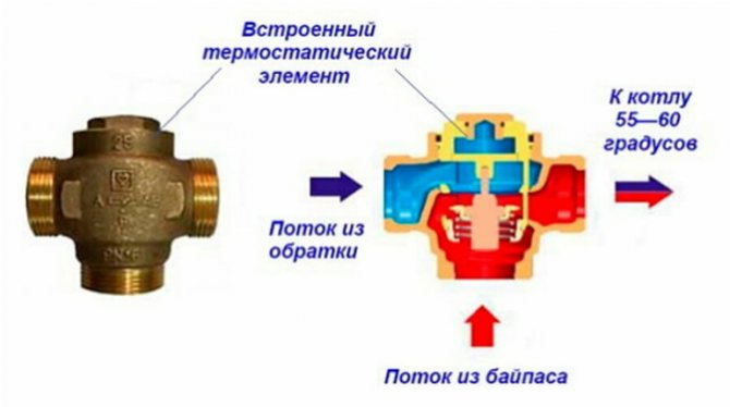
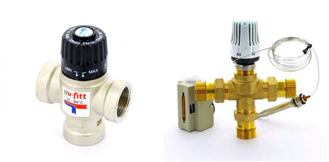
Simple stand-alone models are equipped with a thermostatic element installed inside the case with a coolant outlet temperature already set at the factory. This value remains constant throughout the entire service life.
| Self-contained mixing three-way valve | |
| pros | Minuses |
| Low price | The need to select a valve for the temperature regime of the return flow of the heat generator |
| Control of the temperature regime of the coolant | The temperature set by the manufacturer cannot be changed. |
For manual control, the stem is equipped with a valve or a rotary knob and a control panel with marks, in accordance with which the thermal regime is regulated.
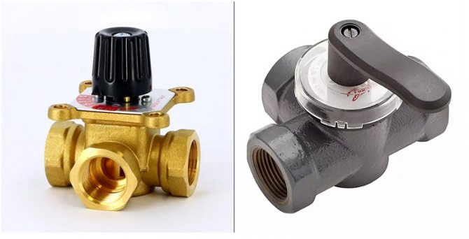
| Manual mixing valve | |
| pros | Minuses |
| Relatively low price | The need for constant monitoring by a person, as a result, a protracted nature of the response to changes in environmental conditions |
| Control of the temperature regime of the coolant | |
| Possibility of changing the temperature regime during operation | Uneven heating of the heating circuit |
The three-way thermostatic valve with a thermostat is equipped with a thermostat filled with a liquid or gas medium that reacts to the slightest fluctuations in the temperature of the coolant.
As soon as the coolant heats up to the set temperature, due to the expansion of the reagent, the piston system of the thermal valve is automatically activated and the branch pipe with hot flows is closed.
Three-way valves with a thermostat can be mechanical or electronic. The advantage of mechanical models is their absolute autonomy. Electronic ones require connection to the mains supply or are powered by batteries.
However, this drawback is smoothed out by the complete automation of the process, ease of setup and advanced functionality - automatic change of the temperature regime by time of day, days of the week, etc.
| Three-way mixing valve with thermostat | |
| pros | Minuses |
| Automatic control of the temperature regime of the coolant | High price |
| The ability to change the temperature regime | An extremely precise setting is required, errors in the set parameters give a small error in the operation of the system |
| Uniform heating of the heating circuit | |
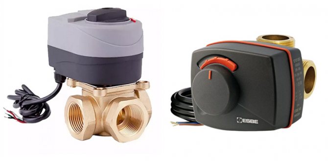
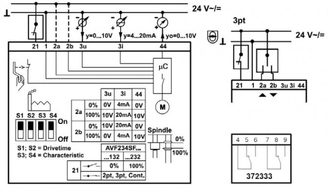
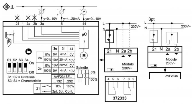
Three-way thermo-valves with an electric drive are controlled by an electronic control unit, which operates on a servo drive. If the temperature regime of the heat carrier exceeds the set values, it is detected by a thermostat installed in the module, which signals this to the controller. He transmits a command to the drive, regulating the flow of cold or hot coolant in the system.
In this case, none of the nozzles is, as a rule, completely closed, and only the volume of the supplied cooled and hot heat carrier is regulated.
| Three-way mixing valve with electric drive | |
| pros | Minuses |
| Automatic control of the temperature regime of the coolant | High price |
| Possibility of changing the temperature regime | Increased power consumption |
| Precise regulation of the heating medium flow temperature | Increased heating agent consumption |
| Uniform heating of the heating circuit | |
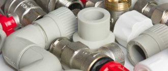
What materials is it made of
Cast iron, brass and steel products are now common. For example, fittings made of cast iron and steel are installed in pipeline systems with a large flow of water or steam. Brass valves are often found in ventilation systems. Their main advantage is their compact size, so the element is mounted even in small rooms with limited water consumption.
A steel or cast iron control valve is recommended. Steel products are widespread, which are as strong as their cast iron counterparts, but much cheaper. When choosing a material, the characteristics of the pressure in the system and the dimensions of the valve itself are taken into account.
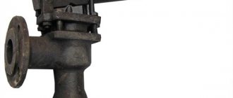
Steel valve
Types of control valves
The fittings differ in several ways.
Depending on the design features, 2 types are distinguished:
- pass-through - in them the nozzles have the opposite location;
- angular - located at an angle of 90 degrees.
Pay attention to how the valve is controlled.
According to this parameter, 3 types are distinguished:
- pneumatic;
- hydraulic;
- equipped with an electric drive.
The electric driving device is a low-power electric motor or retraction solenoids. Of course, there are products with manual control, but they are more difficult to operate, since they do not allow setting the exact parameters. The devices operate on an electrical network with an alternating current of 220 V or constant 24 V.
Certain pass-through nodes operate autonomously, without power supply. Such valves are controlled and regulated by means of a diaphragm and a spring opposing it. As a feedback, a stroke is used, along which the coolant moves - it also directs the membrane in the right direction.
What the two-way valve gives:
- consumption is regulated, resources (water) are distributed and saved;
- more economical heat consumption;
- equipment and networks are protected from pressure drops;
- if used correctly, the valve will extend the life of the connected equipment and the network itself.
Devices are fastened with flanges, threaded or welded. One of the subspecies of the threaded connection is the pin mount, in which the valve is screwed into another device.When the installation is welded, special branch pipes are used.
Separately, we highlight the remote-controlled valve, which is the easiest to operate. Such devices are complemented by electric drives or consoles. It is the control rooms that receive all the current characteristics and parameters of the system. Remotely decreases, increases the pressure or overlaps certain branches of the heating network.
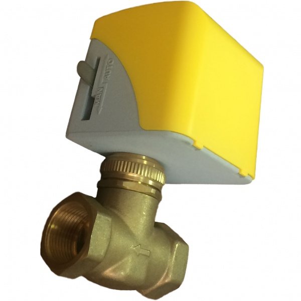
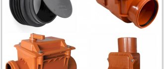
A kind of two-way valve
The device and principle of operation of the three-way valve
The design of a three-way thermal valve is similar to a tee. On 3 sides there are pipe sections (nozzles):
- Two (direct and bypass, in the photo further designated as A and B) are intended for the incoming or outgoing flow in the mixing or separation mode, respectively.
- One (common, in the photo - AB) - for outgoing or incoming (also in the mode of mixing or separating the coolant).
Inside the case are located:
- A rod that provides movement of the shutter mechanism.
- Locking mechanism (shutter).
- 2 seat rings securing the valve (not available on all models).
Depending on the specific modification, the design of the three-way thermostatic valve can be supplemented with other elements necessary for its full operation.
The design of the shutter mechanism assumes the division of three-way valves into 2 main groups - saddle and rotary valves, which differ somewhat in their principle of operation. In addition, a distinction is made between mixing and separating (distribution) thermal valves.
Three-way globe valves are equipped with a rotating stem with a ball, plate or cylindrical valve attached to it. The translational movement of the stem activates the shutter mechanism. Its functions:
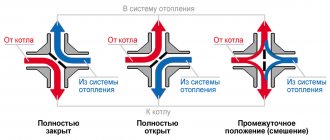
- In the mixing mode, being in the extreme upper position, it blocks the flow of liquid from the branch pipe A, while simultaneously opening the branch pipe B. Being in the extreme lower position, it blocks the flow of the coolant from the branch pipe B, opening the branch pipe A.
- In split mode, the uppermost position of the shutter leads to the closure of branch pipe B and simultaneous opening of branch pipe A. The lowermost position, on the contrary, closes branch pipe A and opens branch pipe B.
Three-way rotary valves are equipped with a 90 ° radial rotation:
- In mixing mode, turning the stem to the left closes port B, opens the coolant flow from port A. Turning the rod to the right closes port A and opens port B.
- In split flow mode, the leftmost position redirects the carrier flow towards port A, and the far right position towards port B.
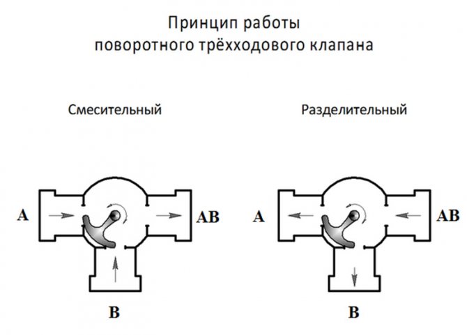
On a note! The common branch pipe AB does not overlap in any of the options, therefore it is characterized by a constant hydraulic mode.
Connection diagram
For water-heated floors, the valve is most often installed in parallel. For its implementation, 2 or 3 heating circuits with a circulating heat carrier must be used. Water supply and pressure are regulated by one or more valves installed in parallel. When mixing the coolant in parallel, the underfloor heating lines must be disconnected in advance.
As a rule, the control taps are adjusted independently, manually, where the required volume of the passed water is set.
Important! If a parallel circuit is used, it is recommended to replace the bypass with a bypass valve. This is done in order to reduce the operating load and save energy supplied to the pump.
The circuit has a minus - the coolant entering the circuit will be the same temperature as the water leaving the return circuit to the boiler. Because of this, hot water is distributed unevenly around the circuits.
Underfloor heating installation scheme
Installation rules for three-way valves
In order for the consumer not to be tormented by the question of how to correctly install a three-way thermo-mixing valve, the manufacturer supplies his products with carefully worked out instructions and applies special markings to each product, which helps to accurately determine the direction of flows:
- The branch pipe marked with the letter "A", the so-called "straight run", is designed to be connected to a pipe with a hot coolant.
- The branch pipe with the letter "B" ("bypass") is connected to the chilled water supply pipe.
- The branch pipe marked "AB" (stroke with constant hydraulic mode) is connected to the main transport line intended for transporting the already mixed heat carrier.
Place of the three-way valve in the heating circuit
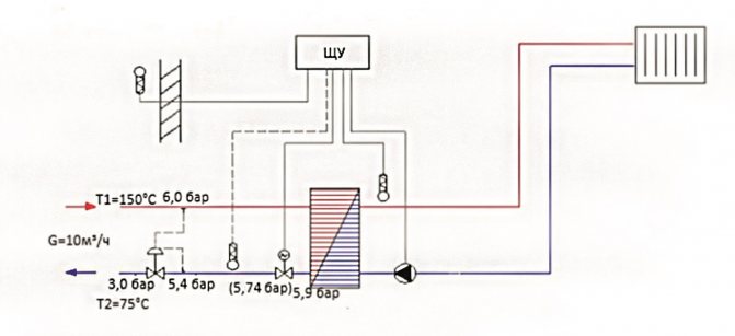
To begin with, consider the general connection diagrams to the heating circuit. In a simplified way, they can be represented as follows:
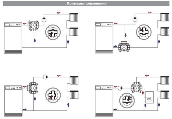
As can be seen from the diagram, three-way thermal valves can be installed both on the heat branch coming directly from the boiler and on the return flow. However, this does not mean at all that absolutely any valve can be installed this way. The capabilities of this or that equipment are determined by the permissible thermal regime specified by the manufacturer in the data sheet.
Below is a more complex scheme that allows you to fully automate the operation of the heating system:
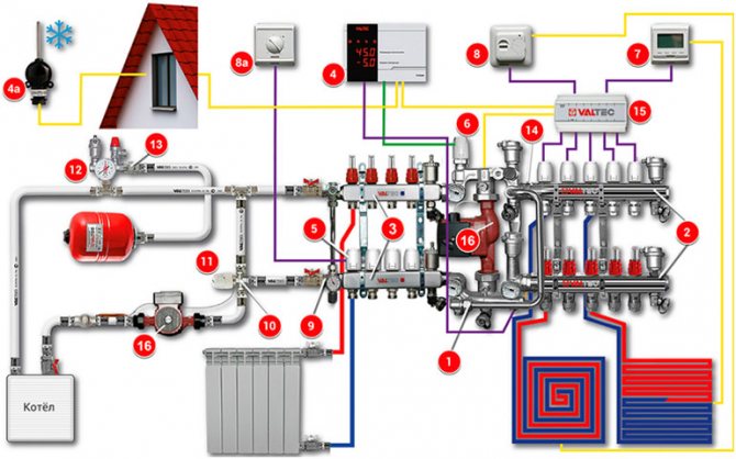
When installing, observe the following rules:
- Before the valve must be installed: pressure gauge, filter, throttle diaphragm (washer).
- After the thermal valve, another pressure gauge is installed.
- In front of the valve, it is advisable to maintain a straight pipe section equal to 5 of its nominal diameters; behind the thermal valve, the length of the straight section should be at least 10 nominal pipe diameters.
- In complex-circuit or unnecessarily long heating lines, the problem of low pressure is solved by installing a circulation pump.
- On horizontal sections, the valve itself is placed in such a way that the electric actuator, thermostatic insert or thermostat is located above it.
- Threaded joints are joined using flax fiber, laid on the thread in 2-3 layers, and sealant.
- In the process of twisting, excessive forces on the mating elements should be avoided; they are not allowed to stretch, compress or bend.
Place of a three-way valve in water supply systems
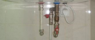
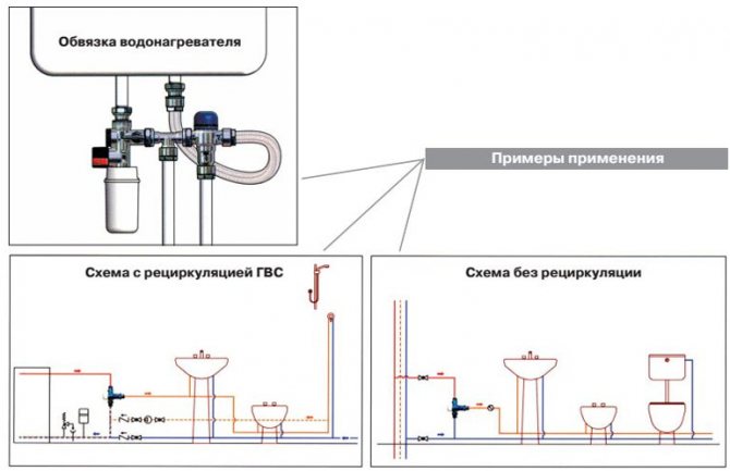
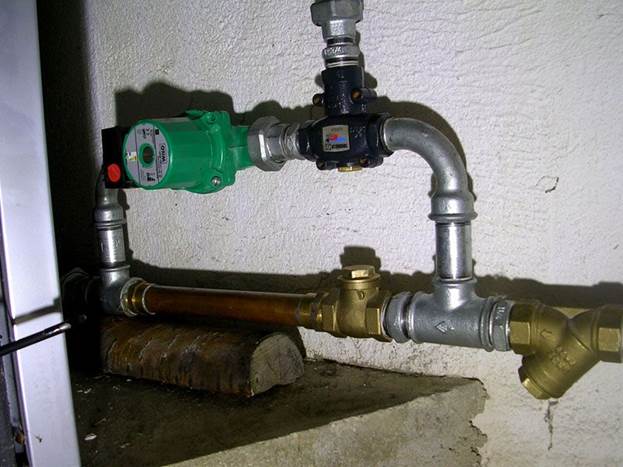
The installation diagram of a three-way valve presented below illustrates the principle of its piping with a water heater and installation options in pressure and non-pressure water supply systems:
Installation features
The procedure itself boils down to the fact that the valve is connected to the necessary pipelines. In order for the fittings to work for a long time and without problems, the connection should be correctly implemented, taking into account all the tips and recommendations. If you lack experience, it is recommended to contact a specialist. Otherwise, the heating system will not be as efficient and economical as it should be.
Before proceeding with the installation work, pay attention to the two-way valve - there is an external or internal thread on its body, onto which the union nut (or fitting) of the pipeline is screwed. For a reliable connection, experts advise to wrap the thread with a sealant, which is suitable for FUM tape.
The set of fittings includes special gaskets to ensure the proper level of tightness. If they are not available, then they will have to be purchased separately, of the appropriate thickness and diameter. The main task is to ensure a tight connection, without distortions on the thread, which will prevent possible leaks. No special tools and devices are required.
Note! Two-way valves do not function in the simplest conditions, namely, under the influence of high temperatures.Because of this, threaded connections can lose their tightness, so the connection procedure must be carried out responsibly.
Expert advice:
- During installation, make sure that there are no forces in the piping.
- Before installing the element on the water supply, the latter should be thoroughly cleaned, removing all impurities. They have a negative effect on the condition of the sealing materials, as a result of which the tightness of the valve is compromised.
- Over time, the device may need to be repaired or dismantled, so leave enough space around it.
- Careful installation is important. If a flange connection is used, it is recommended to tighten the corresponding screws alternately to avoid internal stress. With the threaded installation method, adjusting ties are used, which will allow the valve to be dismantled in the future.
- If it is necessary to purge or flush the entire pipeline system, the valve is removed, and an adapter is put in its place.
Installation is a complex process and largely depends on the chosen scheme. To avoid mistakes, we recommend ordering a valve installation service from specialists.
Valve in the heating system
How to choose a three-way valve
The range of three-way thermo valves is extremely wide. How to choose a model so that it fits the technical characteristics of the home heating system? Pay attention to the following parameters:
- The type of the shutter mechanism is rotary or saddle. The latter provides a tighter abutment of the valve and more accurately regulates the pressure even at high temperatures and pressure drops.
- Control type. It can be autonomous, manual, thermostatic and electric. Electric servo models are most suitable for water floor heating.
- Scope of use. Hot water supply, heating - radiator or underfloor heating. For DHW - dividing, for heating circuits - mixing.
- Valve material. Brass and copper fittings last much longer.
- The diameter of the pipes to which the thermal valve will be connected.
- Connection method - threaded or flanged. For cross-sections over 65 mm, flanged models are usually installed.
Further, you should rely on the data of the thermal and hydraulic calculation of the heating circuit and specifically the area where the installation of the three-way valve is planned:
- Pressure.
- The maximum temperature of the heating medium at the place where the valve is installed.
- Average water consumption (m³ per hour).
These data must necessarily coincide with the marking on the valve itself or the information in the accompanying documentation for the product.
On a note! The 3-way thermo-mixing valve should not be confused with a similar valve. Despite the similar design and principle of operation, the difference in the control system is significant. For complex heating systems, it is better to use a valve, and for small and as simple as possible, a manually operated tap is quite suitable.
Popular three-way valve manufacturers
Among the numerous manufacturers of three-way thermal valves, I would single out the following five leaders. They specialize in the production of engineering plumbing, thermostatic equipment and are actively introducing the latest energy efficient technologies:
- ESBE (Sweden).
- IMI-HEIMEIER (holding, which includes 3 production complexes).
- Danfoss (Germany).
- HERZ (Austria).
- Valtec (Italy, Russia).
Valtec is a special project for the production of various engineering sanitary ware adapted to Russian realities. A special plus is a reasonable price and a long warranty period for products.
How much do three-way valves cost
The cost of a device consists of many aspects - the material from which they are made, technical equipment, brand reputation. Whether it is worth overpaying for it is up to you.