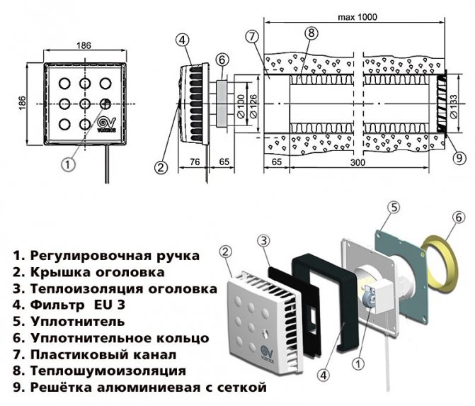
Components
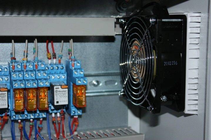
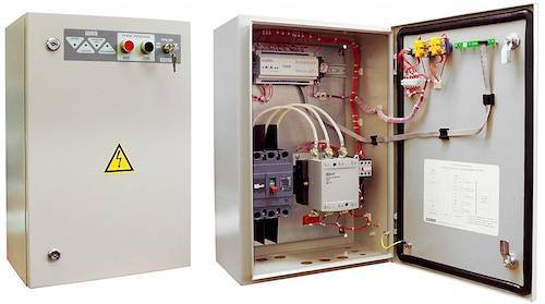
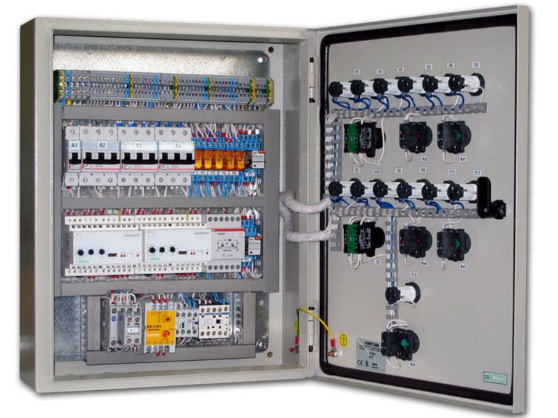
The fan control cabinet is equipped with a power supply, controllers, converters and a large number of on / off switches. The switches, in turn, are connected to electric heaters, recuperators, fans, water heaters and refrigeration units. A mandatory element of the switchboard is a manual control unit, which takes over the regulation and control functions in the event of a failure or malfunction of the automation. In addition, all cabinets are equipped with emergency alarm sensors that are triggered in the event of an emergency or pre-emergency situation.
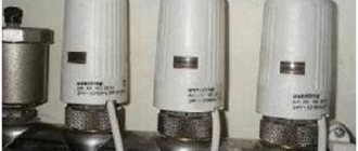
Sensors, which are a kind of receptors and collect information about the performance of each unit, play a special role in monitoring the operation of ventilation systems. With their help, you can get a visual picture of the pollution of air flows, their temperature and humidity, as well as the speed of movement of air masses and the frequency of rotation of the fan blades. Temperature sensors are available in both digital and analog versions, and when the temperature regime inside the system changes, they help to switch the entire installation to another mode. Humidity sensors work in the same way. The information received by the sensors goes to automatic regulators, which, in turn, adjust the operation of key components of ventilation systems.
By location, the sensors are divided into external and internal. The former are often called atmospheric and are installed on the outside of buildings. Internal, in turn, are subdivided into channel and surface models. Channel ducts are installed inside the air ducts on the walls or across the movement of air masses. Surface are placed on the surface of the nodes and carry out the removal of parameters from these devices.
Controllers are an equally important element of control cabinets. The devices receive information from the sensors and process it automatically. After processing the parameters, the controllers send a signal to the main units of the ventilation units, such as fans, air heaters, refrigeration units, after which they change their operating mode. Functionally, the controller can either serve several devices, or interact with only one of them. Versatile models are often equipped with microprocessors, which makes them less bulky and easy to fit in a small cabinet or stand.
Another element of the shields configuration is the fan blade speed converters. Thanks to these devices, it is possible to regulate the number of engine revolutions, thereby significantly reducing the amount of electricity consumed by the installation. In addition to cost savings, this leads to a significant reduction in the wear of the fan parts and extends the overall life of the air handling unit.
General information
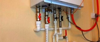
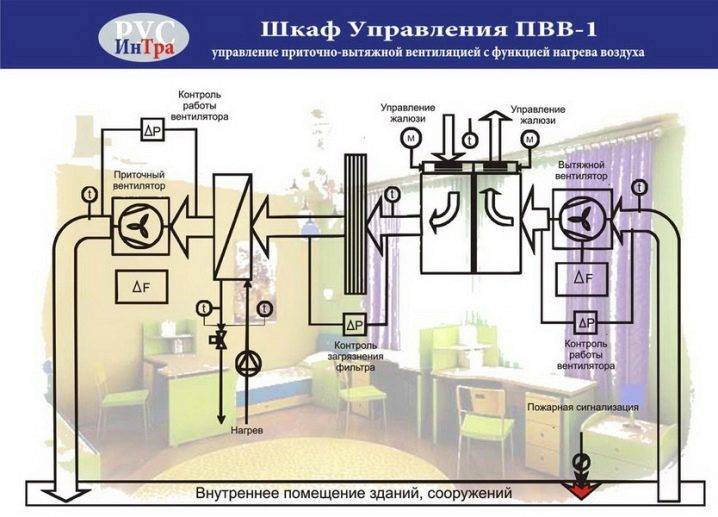
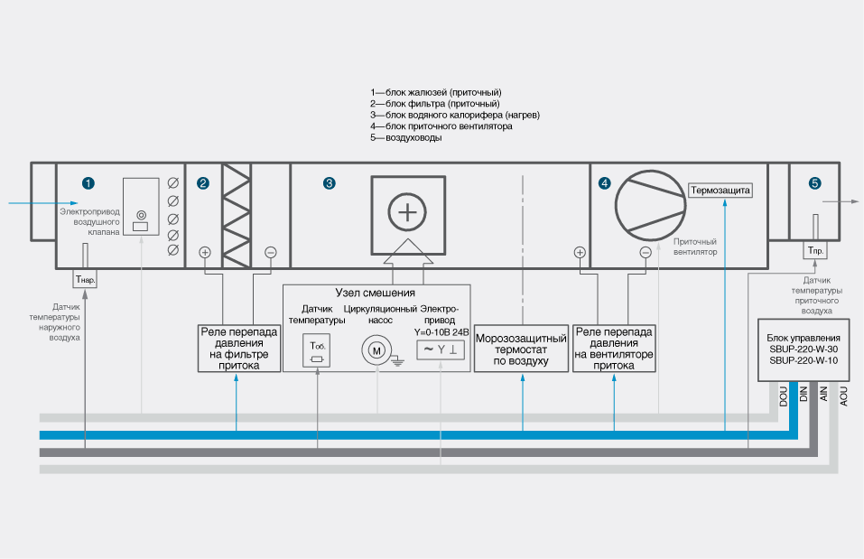
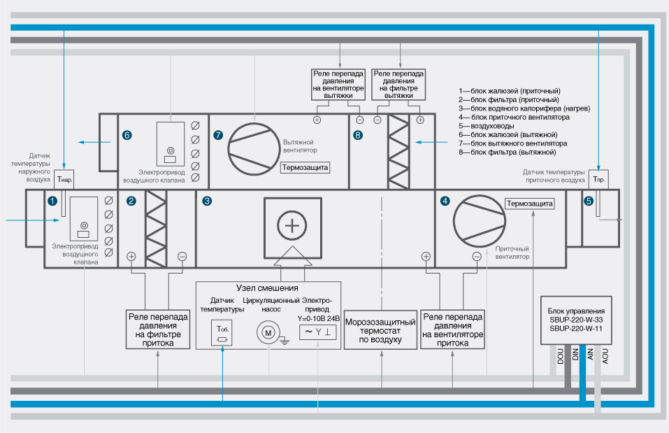
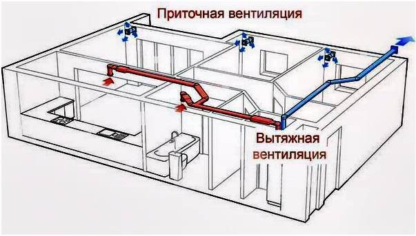
ACS ventilation is designed to control and manage supply and supply and exhaust ventilation systems of buildings with a different set of equipment, which may include: recuperator, cooler, air heater, control valves and pumps in the cooler and heater circuit, air dampers, filters.
Tasks to be solved when introducing ACS:
- automatic maintenance of the set temperature and air exchange rate in the manned room;
- ensuring fire safety - control of fire-retarding valves;
- timely diagnostics of ventilation equipment failures.
- maintaining the air temperature in the serviced premises within the limits set by the controller program;
- continuous automatic protection of the water heat exchanger against freezing by water temperature and supply air temperature, control of air filter contamination in the supply system;
- operation of ventilation systems in the "Day" / "Night" and "Winter" / "Summer" modes;
- monitoring the state of the controlled equipment.
The ACS of ventilation exchanges information with the dispatching console, providing the following capabilities:
- transmission to the dispatching console of technological parameters, messages on emergency situations and data on the operation of executive mechanisms;
- remote control for individual mechanisms, if necessary, while maintaining automatic control for the system as a whole, and incorrect operator actions are blocked;
- receiving from the dispatching console commands for unscheduled switching on and off, as well as assignments for the temperature in the serviced premises.
In addition to the main control mode from the dispatching console, it is possible to control the ventilation systems locally from the push-button control stations (KPU) located in the serviced premises.
The hardware and software platform of the ACS provides high flexibility in configuration and programming. As a result, the following characteristics of the ACS are provided, which distinguish it from similar products:
- the ability to connect small ventilation systems to controllers of large ventilation systems without installing additional control cabinets;
- the ability to connect the actuators of other engineering systems (fire protection valves, smoke exhaust fans, pumps, SPS, etc.) to the controllers of ventilation units;
- the possibility of implementing modifications to the controller and control programs in a short time and at low cost in case of changes in the original project of automation of engineering systems;
- flexibility of control algorithms, which makes it easy to modify them during the design of engineering systems in the event of the appearance of the corresponding customer requirements;
- the ability to transfer information to the upper level using any standard protocols requested by the supplier of the dispatching system.
Architecture
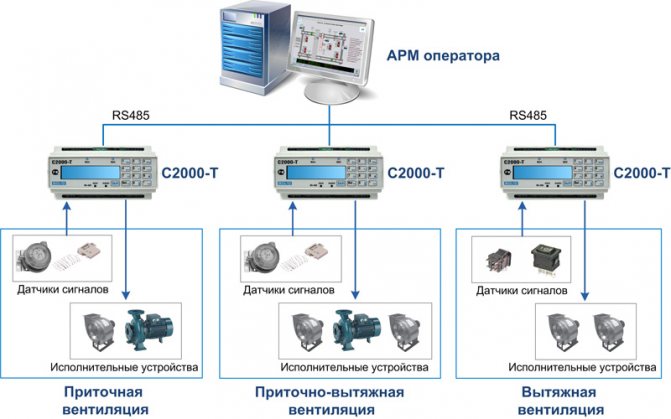
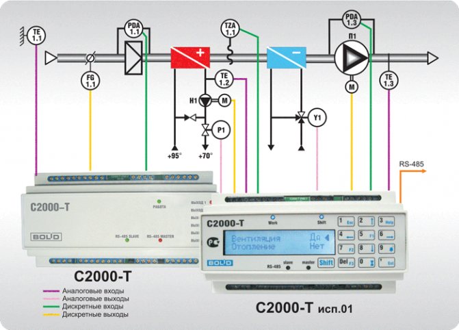
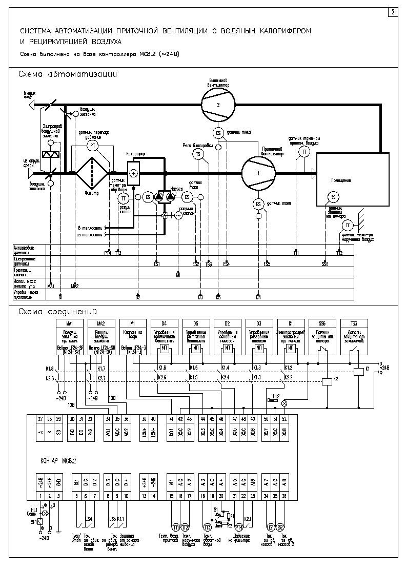
The automated ventilation control system (ACCS) is represented by three hierarchical levels.
The first (lower) level includes signal sensors and actuators.
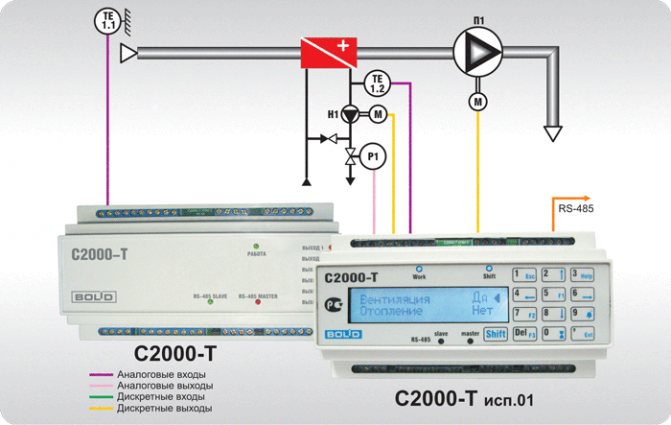
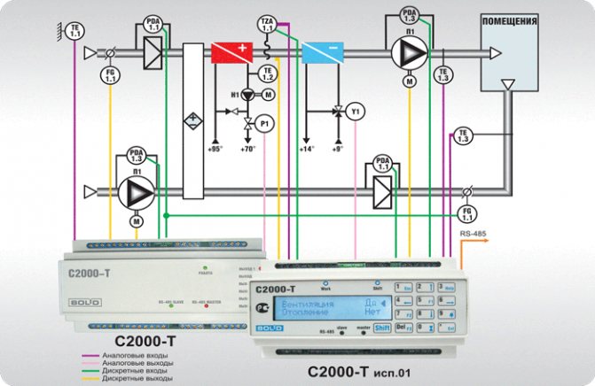
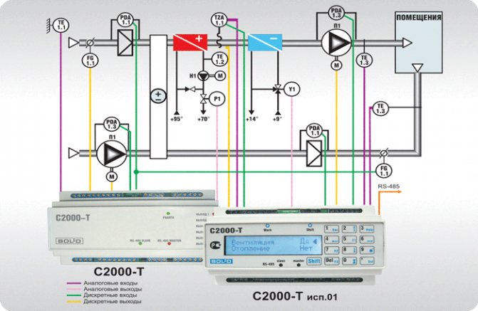
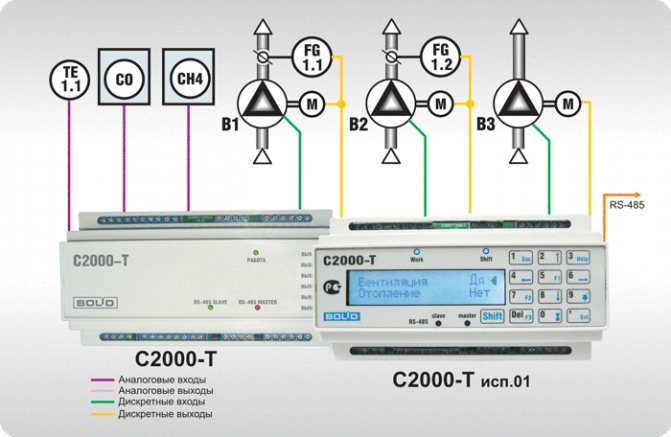
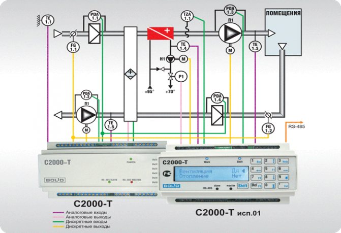
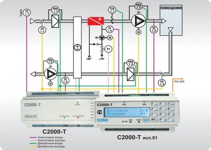
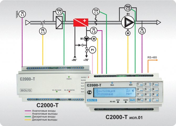
The second (middle) level consists of S2000-T controllers manufactured by BOLID. The controllers ensure the performance of functions of control, regulation and management of engineering equipment in an amount sufficient to maintain the operation of all three types of ventilation systems (supply, exhaust, supply and exhaust) in the ratio "one system - one controller". For exhaust ventilation, two ventilation units are connected to the controller. All algorithms are ready and only require configuration.
| P / p No. | Parameter name | Signal type | Forced ventilation | Exhaust ventilation | Supply and exhaust ventilation |
| 1 | Outside air temperature | AI | + | — | + |
| 2 | Room temperature | AI | — | — | + |
| 3 | Supply air temperature | AI | + | — | + |
| 4 | Return water temperature | AI | + | — | + |
| 5 | Water heat exchanger protection | DI | + | — | + |
| 6 | The filter is dirty | DI | + | — | + |
| 7 | Break of the supply fan belt | DI | + | — | + |
| 8 | Broken exhaust fan belt | DI | — | — | + |
| 9 | System status (standby / active) | DI | + (2 pcs.) | — | — |
| 10 | Signal from the contact of the emergency switch of the fan | DI | — | + (2 pcs.) | — |
| 11 | Fan manual switch status (start / auto) | DI | — | + (4 pcs.) | — |
| 12 | Exhaust fan control (start / stop) | DO | — | + (2 pcs.) | + |
| 13 | Emergency mode indication output | DO | — | + (2 pcs.) | + |
| 14 | Supply fan control (start / stop) | DO | + | — | + |
| 15 | Blinds drive control (open / closed) | DO | + | — | + (2 pcs.) |
| 16 | Circulation pump control (on / off) | DO | + | — | + |
| 17 | Water heater valve control | AO | + | — | + |
| 18 | Water Cooler Valve Control | AO | + | — | — |
| 19 | Rotary recuperator control | AO | — | — | + |
| Note: AI - analog input signal of thermal resistance (TCM, RTC) AO - analog output signal of constant voltage (0-10 V) DI - discrete input signal of the "dry contact" type (24 V) DO - discrete output signal of the "dry contact" type (24V) | |||||
The third (upper) level includes an automated workstation (AWP) of the operator based on SCADA CIRCLE-2000, combined by functions with an archive server.
Analog and discrete signals from sensors and actuators of the supply, exhaust and supply and exhaust ventilation are fed to the controllers, undergo primary processing and then via the digital RS485 interface (Modbus protocol) are transmitted to the operator's workstation for the purpose of their further processing, display and storage. The operator's workstation is also used to remotely control the actuators of ventilation systems.
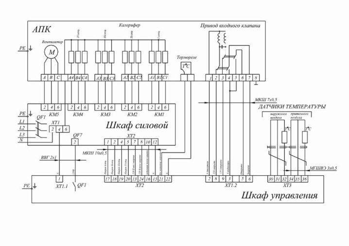
Device diagram
Connection of control cabinets is carried out according to the standard scheme and is regulated by GOST R51321-1. Cabinets, stands and panels are installed in corridors, panel rooms or utility rooms. In the presence of technical conditions, ventilation and fire control units are located in one cabinet, which is placed in the control room. This will provide quick access to the emergency and service ventilation control panels and allow quicker response to system problems.
The rooms in which the boards are installed have special requirements for the level of humidity and temperature. Devices must be reliably protected from direct ultraviolet rays, water drops and dust. Magnetic vibrations and radio interference can also adversely affect the correct operation of the devices, therefore their influence on the devices should be limited. The temperature range at which the operation of control cabinets is allowed is from -10 to +55 degrees. Installation of the device requires mandatory grounding, and the frequency of the mains current should not exceed 50 Hz. As a power source, 220 and 380 V power grids are used.
The main requirements of the layout are to find all control devices on the same stand and in the same plane. The most important units responsible for the safety of the device must be equipped with light indicators and preferably connected to a personal computer. In addition, the devices responsible for the correct operation of the main units must be equipped with two types of control: manual and automatic. The most convenient for operation are cabinets equipped with a remote control, which allow a person who does not have much experience in ventilation control to monitor its operation. In addition, the device connection diagram should be simple and extremely easy to understand. This will help in the event of an emergency to turn off the unit yourself, without waiting for the arrival of repair services.
Calculation of ventilation systems
The calculation of the ventilation of the room at the first stage requires the correct choice of equipment, which will have the necessary performance characteristics in terms of the amount of blown air (cubic meter / hour).
It is also considered very important to consider such a parameter as the frequency of air exchange. It characterizes the number of complete air changes within one hour inside the building.
In order to correctly determine this parameter, it is necessary to take into account the norms and rules of construction.The multiplicity depends on the purpose of using the premises, what is in it, how many people, etc.
The calculation of ventilation of industrial premises for this indicator also involves accounting for equipment, as well as the characteristics of its operation and the amount of heat or moisture that it emits. For premises intended for human habitation, the air exchange rate is 1, and for industrial premises up to 3.
Conciseness measures form a performance value, which can be as follows:
- from 100 to 800 m³ / h (apartment);
- from 1000 to 2000 m³ / h (house);
- from 1000-10000 m³ / h (office).
Also, it is necessary to correctly design and install air distributors. These include special air diffusers, air ducts, bends, adapters, and so on.
Providing reliable and correct ventilation is an extremely important and necessary system in any building.
What is SHCHUV for, where is it used
Small household ventilation systems used in multi-storey buildings and the private sector do not require any additional appliances. They are controlled remotely, using a remote control, or manually.
Unlike household systems, industrial systems are distinguished by a significantly longer network length. Many functional devices, primarily fans, are initially installed in hard-to-reach places. Due to limited access, control is carried out using a unit equipped with a whole set of special equipment.
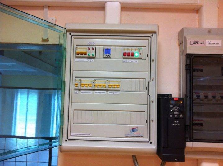
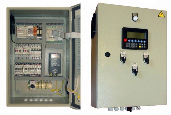
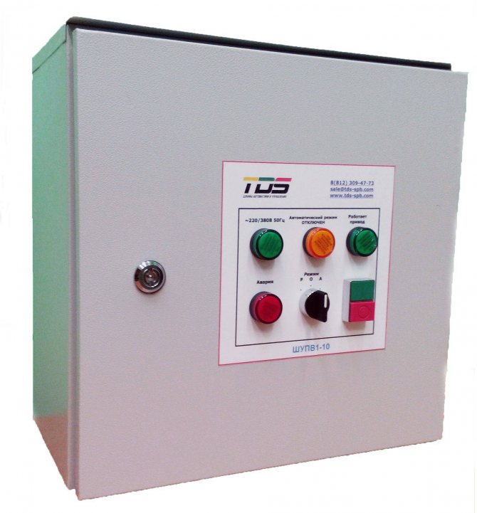
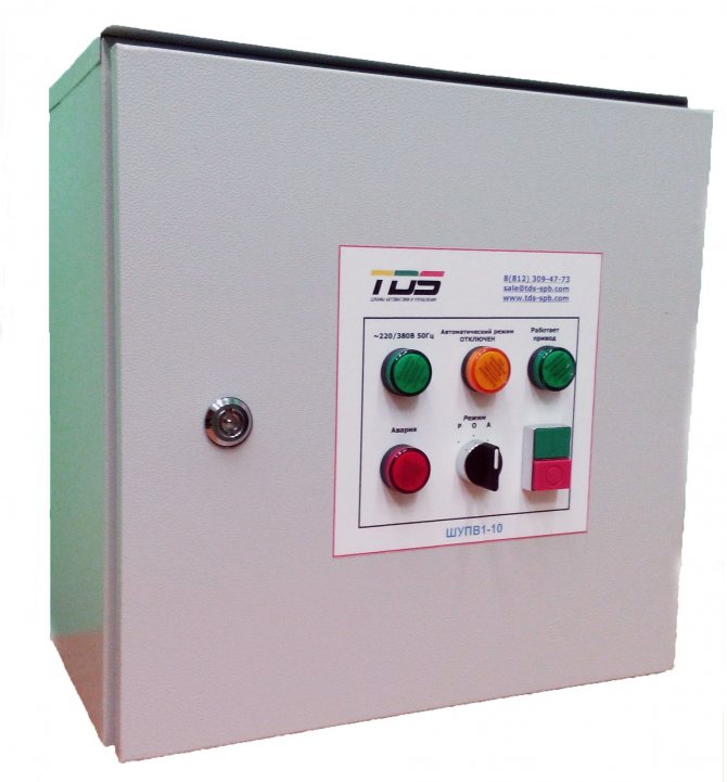
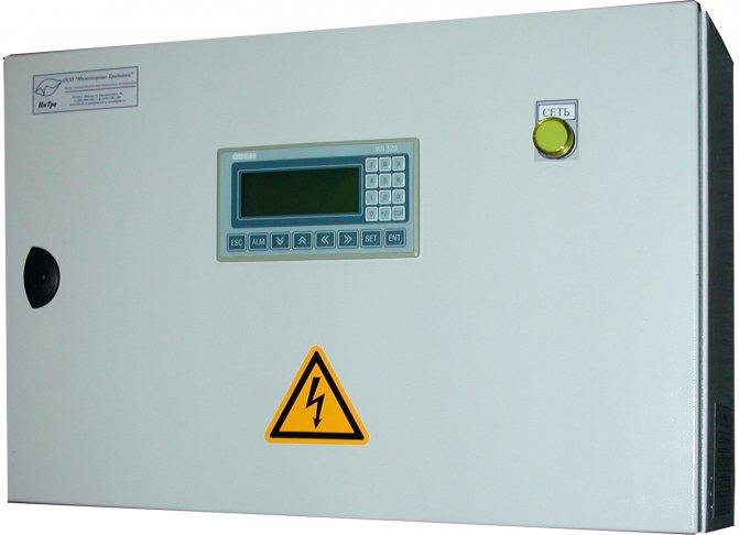
The modern ventilation control panel - SHCHUV is manufactured in the form of a panel on which the adjusting indicator devices are located, as well as in the form of metal cabinets fixed to the wall or installed on the floor. The inner space with the equipment located here is protected by hinged doors. To restrict the access of unauthorized persons, they are locked.
The main tasks that the ventilation control panel solves are as follows:
- Control over equipment, devices and equipment that are part of ventilation systems.
- Protection of controlled devices in the event of emergency situations caused by overheating, improper installation and connection, short circuits.
- Adjustment functions - setting the required parameters for the performance and power of the equipment.
- The ability to program individual components and assemblies or the entire system for a specific period, from 1 day to 1 month.
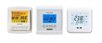
- The control and adjustment processes of the ventilation control panel are greatly facilitated by the installed display.
- Each of the rooms can maintain its own temperature, which can be changed at the right time.
- The air filters are monitored, the degree of their pollution, as well as the condition of the inner walls of the air ducts.
- Control over the operation of seasonal equipment, which is exposed to negative influences due to sudden changes in outdoor temperature.
The control panel of the ventilation system installed at the facility allows, being in one place, to constantly monitor the work processes and the condition of all equipment. In the event of a breakdown or stop of some devices, timely detect and eliminate them.
Functions of automatic ventilation cabinet
Thanks to the improvement of equipment in the field of ventilation automation, it became possible to exclude the human factor from the operation of the ventilation control cabinet. Automation guarantees a high level of safety of the huge functionality that ventilation controlled by the cabinet actuators possesses.
The wide range of ventilation control cabinets includes:
- Connection of any ventilation elements with different physical characteristics and different ports for installing the system.
- Ability to monitor mains voltage.
- Control of special electric valves to ensure uninterrupted power in the mains. Increases the operation of devices, excluding their overheating, short circuit, overload.
- Control of the set parameters for the room and the fan speed.
Standard functions
A conventional ventilation control cabinet has the following functions:
- Control of the heating temperature of a single element of the ventilation system.
- Control over the parameters of the air valve actuator.
- Monitoring the cleanliness of air filters. In case of contamination, an audible signal is sent to the ventilation equipment control unit.
- Control of a valve for moving air masses to maintain the set air temperature in the room.
- The ventilation equipment unit is controlled manually, switching on and off.
- Elimination of overheating and short circuit of the pump motor.
- With the help of light indicators, you can get information about the operation of the system as a whole.
- Possibility of extending the stopping time of movement: both supply and exhaust air, by SHUV fans (ventilation control cabinet).
- Maintaining a log of failures in the operation of the forced ventilation system.
- Control over icing of parts of freon coolers.
Advanced functions
The set of advanced functions depends on the specific model of the ShUV device. Functions such as are often used:
- Control of special valves to regulate the pressure in the event of a fan belt break.
- Automatic control over the amount of carbon dioxide.
- Saving all work data in logs after a power outage.
- Control over a special chamber for mixing air flows.
- Programming a week ahead of the entire workflow.
- Monitoring the parameters of the cooling valve.
- Control by means of an electric heater.
- Using the remote control.
- Implementation of effective work with sensors designed to control various parameters of a room using a cascade method.


Purpose of ventilation control cabinets
Today the ventilation control cabinet is an integral part of the air exchange system. It greatly facilitates the work of equipment for providing fresh air to the premises or utilizing waste gases.
We recommend that you familiarize yourself with: Corrugation for ventilation: what it is and how it is used
When purchasing a distribution unit ШУВ, it is worth being guided by the control functions for a specific ventilation, according to the conditions of its operation.
For a ventilation system that provides smoke removal from the premises, a ShUV is needed, which will provide increased safety, will control the temperature of the air in the room and its humidity. And also to maintain the required indicators in the norm and move the air masses at a certain constant speed.
The purpose of the ventilation control cabinet depends on the type of air exchange system:
- With recuperation or purification of air from harmful substances in the working area.
- With electric heater.
- With a water heater.
- With smoke emission function.
- Exhaust, supply or supply - exhaust ventilation (ШУ PVV).
All ventilation control cabinets operate in two modes:
- Summer mode. Means that the air temperature control is disabled. When the supply air temperature drops, the automation switches on the protection mode according to the parameters entered in advance. Temperature control is carried out using sensors.
- Standby mode.
At this time, the SHUV model - Aries is popular.It meets all the requirements for ventilation control cabinets in production, regardless of their purpose. The Aries device provides control over the air exchange system with a high level of security.
To control one fan, it is possible to use a ShUV1 smoke exhaust cabinet. To control several fans, a cabinet of the ShSAU-VK type is suitable. The price directly depends on the number of controlled fans.
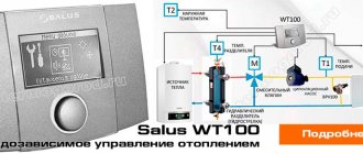
What is automation for ventilation systems
Today, automatic ventilation control systems are represented by a large range of all kinds of technical devices. All of them, from thermostats to sophisticated computerized modules, are designed to facilitate the management and control of forced ventilation systems. A variety of equipment makes it possible to solve automation problems at any facility, regardless of its characteristics and purpose.
Based on the operational and technical requirements, a different approach to the manufacture of automated ventilation control panels is possible:
- At some sites, you can get by with standard modules produced in the form of cabinets with control devices installed in them.
- In other cases, installers have to manually assemble complexes adapted for complex supply and exhaust ventilation, taking into account specific tasks.
The difference in approaches is due to the need to ensure the effective functioning of ventilation and the creation of comfortable conditions for residents or employees in the internal premises of the building, regardless of the season and external weather conditions.
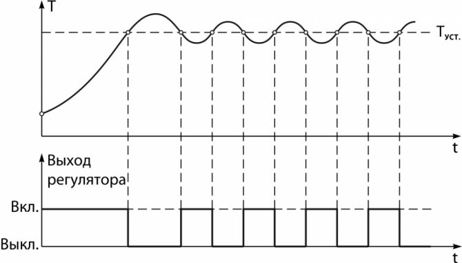
The ventilation mechanisms are controlled by a set of sensors installed inside the premises. Some of them operate on the principle of a thermostat - as the temperature inside the building rises, the fans automatically turn on, which ensures the flow of fresh air.
Modern automated systems are equipped with elements of artificial intelligence and more sophisticated instrumentation.
Structurally similar modules consist of three groups of nodes:
- Sensors - devices that transmit information about the environment - thermostats, air humidity meters, gas analyzers. They transmit the collected data to the analyzing center.
- The control center collects and processes the information coming from the control sensors, and, based on the obtained analysis, issues commands to the control mechanisms to change the operating mode.
- Actuators are units that carry out mechanical actions. This group includes: fan speed converter, servo drives for adjusting the position of the dampers, etc.
The control centers analyze the ratio of oxygen and carbon dioxide in the air, the percentage of humidity, and, if necessary, issue a command to ventilate the room. When a fire is detected, the highly intelligent electronics automatically blocks the flow of fresh air, preventing the spread of the fire.
In normal mode, the automation ensures the smooth functioning of all units and mechanisms of ventilation systems without the involvement of an operator.
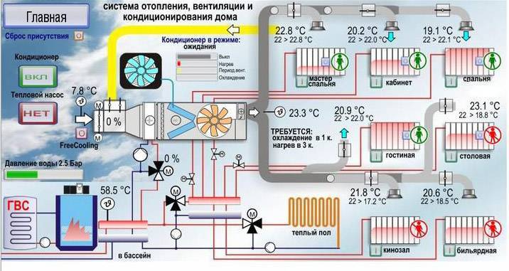
Computerized modules transmit information about the operating mode, about the readings of the sensors to a single control panel. This allows the operator, if necessary, to adjust the operation of the automation, and change the settings remotely.
Depending on the specific situation, one of 3 instrument control modes is used:
- Manual. The ventilation is controlled by an operator located directly in the control room, or behind a remote control panel.
- Autonomous.The equipment operates in accordance with the established settings, regardless of other engineering systems installed in the building.
- Auto. Control devices are integrated into the general management of all engineering complexes of the building. The ventilation operation is synchronized with other devices and sensors located in the house - for example, with a fire alarm, other emergency sensors.
Thus, the automated complex plays the role of a managing control center. It starts ventilation, stops it, processes the sensor readings and sets the desired mode depending on temperature, humidity and other parameters.
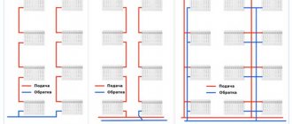
Types of supply and exhaust systems
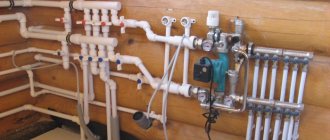
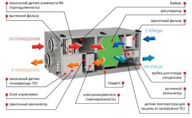
The most efficient ventilation systems are supply and exhaust, including recuperators in the circuit. These devices are heat exchangers that use the energy of the exhaust air. In this case, the inlet stream and the outlet do not come into direct contact. The recuperator can be rotary, plate or containing an intermediate heat carrier. The rotary one is highly efficient, but it is considered the most expensive. Its use is uneconomical when the outside air temperature during the cold period does not drop below 15 degrees below zero. At the same time, air handling units with rotary recuperators used in northern latitudes provide a twofold saving in energy costs for space heating. The plate version of the device is more affordable and belongs to the budget segment.
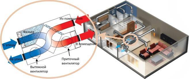
Installation with recuperator
In the cold season, the incoming air stream heats up in the room and, when it leaves, gives off heat to the newly incoming stream. The lack of mixing guarantees a constant supply of fresh, clean air and the removal of waste. In summer, in hot weather, the device works in the reverse order. The warm stream, entering the room, cools down, and when it leaves, it takes away heat from the newcomer.
General exchange ventilation of circulation type is a cheaper type. The air entering from the outside receives heat by directly contacting the waste.
At the same time, the cleanliness of the air in the room can no longer be the same as in the above-described version. Circulation systems cannot be installed in buildings where the atmosphere may contain carbon monoxide and combustible gases, toxic substances and other components dangerous to life and health.
Another disadvantage of forced circulation ventilation is its ineffectiveness when the outside temperature drops below zero.
The most expensive options for air handling units with forced ventilation are systems equipped with air conditioners. The devices allow you to regulate the temperature regime in the room over a wide range and provide comfortable conditions all year round. The system is equipped with a heat pump and a filtration circuit for air purification.
Each of the forced ventilation is provided with a control system. The most expensive options are supplied with sensors and "smart" electronics, capable of regulating the modes independently, according to a predetermined program.
For ventilation of buildings, especially multi-storey buildings, not only mechanical air circulation can be used. The pressure difference inside and outside the room is able to create the flow necessary for ventilation. The supply and exhaust ventilation with natural circulation is based on this principle. In this case, the following nuances are taken into account:
- To place the air intake, the side of the building is usually chosen, which is most often blown by the wind.
- The retraction is made from the opposite side
- The air intake itself is equipped with a deflector that enhances the incoming flow.
Such a system is distinguished by its simplicity of design and low cost.However, simplicity excludes the possibility of saving heat and many of the advantages provided by installations with forced ventilation: ionization, cleaning, humidity control.
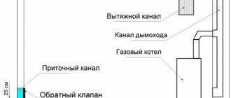
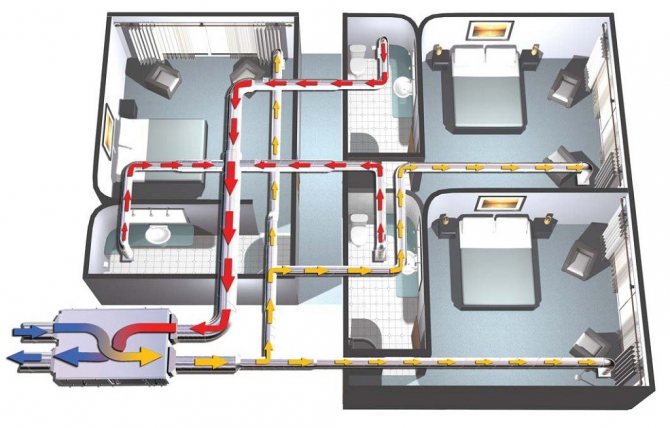
How natural ventilation works
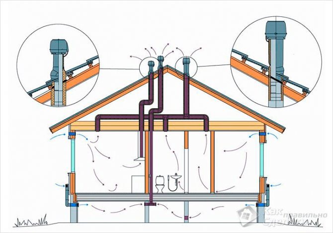
In the photo, the work of natural ventilation in a private house.
- The principle of operation of natural ventilation lies in natural air exchange, which is created due to the difference in pressure outside and inside the premises.
- When the outside temperature is below its value in the building, the heated air is forced out through the ventilation ducts. It is replaced by streams of fresh air through the vents or supply valves. In the rooms, it warms up and flows out again.
- With the arrival of summer, the outdoor air temperature rises higher than the indoor air, so the efficiency of natural ventilation decreases.
- As a result, residents have to create drafts by airing the rooms - opening windows and doors.
Arrangement of the system
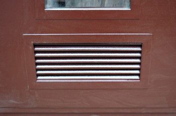
A door with a ventilation grill.
In order for the principle of natural ventilation in a building to be observed, certain conditions must be created for it.
- Provide exhaust ducts when designing the system... They must be equipped in those rooms in which polluted, hot, waterlogged air accumulates (toilet, bathroom, laundry, bathhouse, kitchen).
- These air ducts should be introduced into the general ventilation shafts, through which the exhaust flow flows into the street..
Note! In order for the ventilation ducts to be able to remove the air outside, the supply of fresh streams should be ensured. It can flow into a building in various ways: through ajar doors, windows, vents, ventilators and supply ventilation valves. The instruction warns that street traffic must flow into all rooms of the house.
- If it is impossible to equip a ventilation duct in the room, then a 1.5 / 2 cm gap must be made in its door from below.
- At the bottom of the doors of those rooms where there are air ducts, it is advisable to make several decorative holes or install a small grate.
How to improve air circulation
Supply valve design.
New buildings are now being built on the principle of energy saving, i.e. they are sealed. The same happens if you equip an old building with double-glazed windows.
On the one hand, heat loss sharply decreases, on the other hand, the inhabitants of the house begin to experience oxygen starvation.
- To prevent this phenomenon, supply valves should be installed in windows or external walls.
- If you order new windows, order fixtures with them right away. The price of the blocks will increase slightly, but you do not have to fiddle with installing the valves separately.
- It is necessary to install the devices at a height of about 2 m. This is necessary so that the cool supply air has time to warm up before it reaches the residential high-rise level.
However, the installation of supply valves also does not always help.
This happens for the following reasons.
- Insufficient draft in summer when the outside air is warmer than the inside.
- A sharp increase in the volume of polluted or spent atmosphere as a result of the simultaneous implementation of hygiene procedures, food preparation, general cleaning, etc.
- Insufficient cross-section of the exhaust duct pipes due to erroneous design.
In these cases, in order to improve air circulation in rooms, natural ventilation should be replaced with forced ventilation.
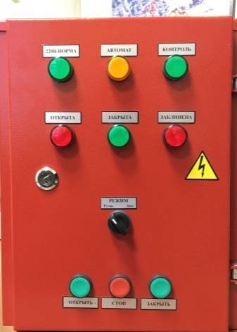
Functions of automatic ventilation cabinet
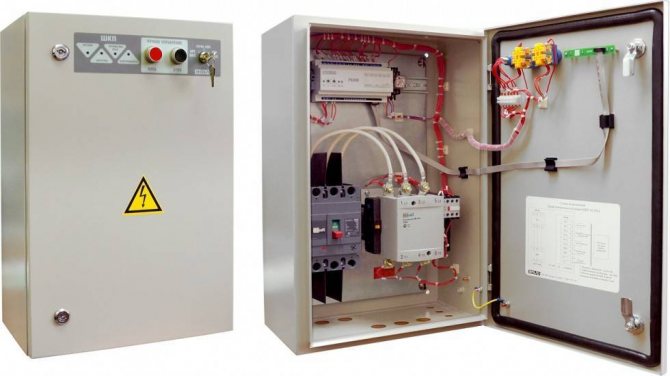
ventilation control cabinet "Rubezh-4A
Features of ventilation control cabinets:
- maintain the required constant power of the power grid;
- allow you to conveniently connect lines of different power voltages to different terminal blocks;
- control the intensity of rotation of the fans, start them smoothly and prevent phase imbalance;
- equalize power, preventing equipment overheating, overload and short circuits;
- control the voltage in the network autonomously, remotely or locally.
The supply and exhaust ventilation control cabinet operates in standby or summer modes. In summer mode, the air temperature is not controlled. When the supply air temperature is low, the cabinet automation switches the supply ventilation control to protection mode.
Standard functions
- Manual stop and start;
- compatible with temperature sensors for supply air, outdoor air, and return heat carrier;
- records the temperature of the fan motors contacts;
- regulates the function of the air valve actuator;
- prevents short circuits and overloads of the pump motor;
- controls the drive of the heat supply valve;
- prevents freezing of water heaters and freon coolers;
- prevents overheating of the electric heater;
- prolongs the stop of the supply air fan;
- gives signals about the need to clean the air filters;
- stops and de-energizes equipment in the event of a fire alarm;
- notifies with the help of light indication about the work of the system;
- records accidents in a special log.
Advanced functions
- Prevents pressure drops when the fan belt breaks;
- Provides frequency conversion for fans;
- Regulates indoor air temperatures in a cascade manner;
- compatible with a thermosensor on the hood;
- notifies about an accident with light indication;
- connection of remote control is possible;
- controls the operation of the air valve;
- provides connection of additional fans;
- two-phase control of the compressor-condenser unit;
- five-phase control by an electric heater;
- controls the mixing chamber;
- prevents freezing of the recuperator and rotary recuperator;
- controls air humidifiers;
- programmable for 7 days;
- controls the cooler valve;
- controls the recirculation dampers;
- in case of insufficient heating power, it reduces the rotation speed of the fan blades;
- saves data in memory after power outage;
- controls the level of carbon dioxide.
On request, manufacturers equip the cabinet for automatic ventilation control with additional features:
- work without sensors;
- recording of reports on the system operation;
- cold recovery;
- dispatching remote or local control.
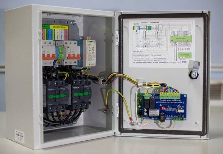
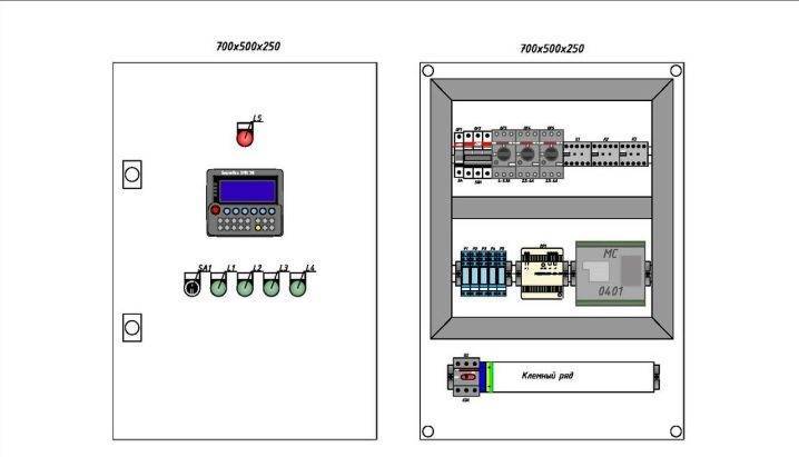
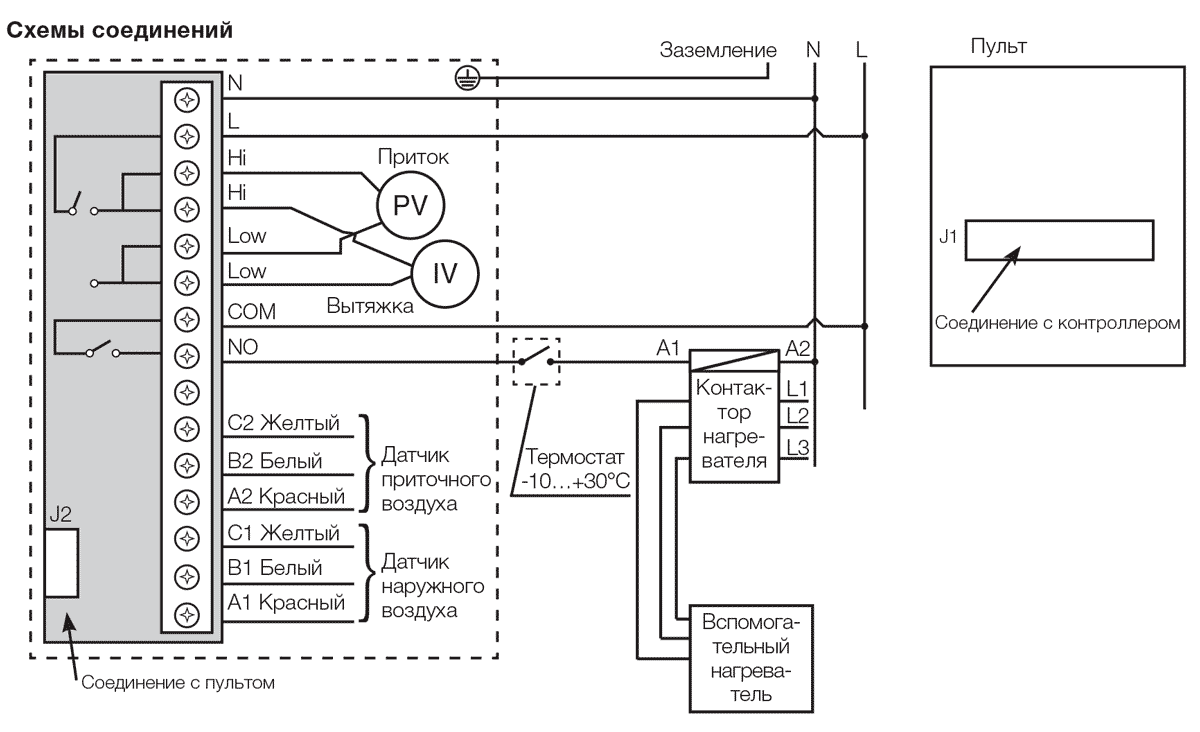
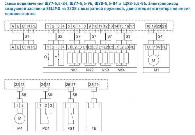
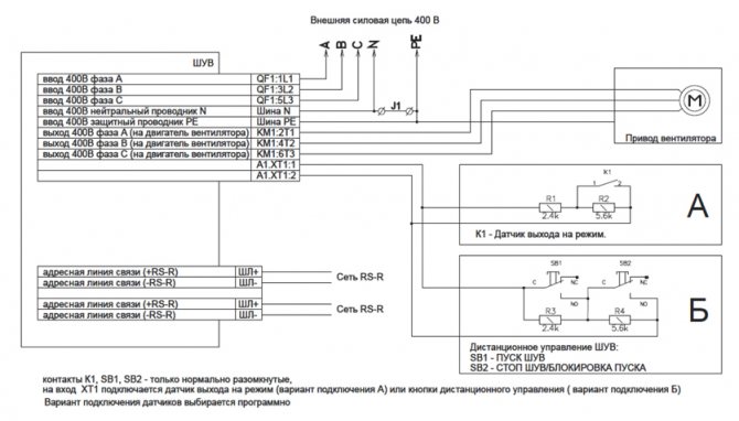
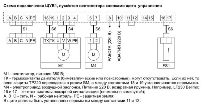
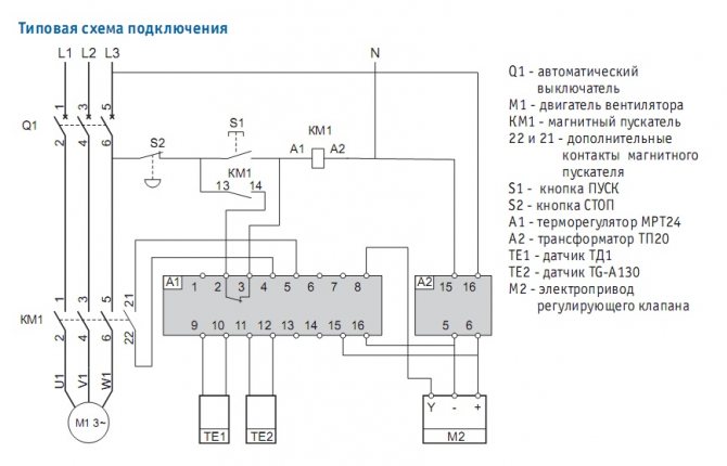
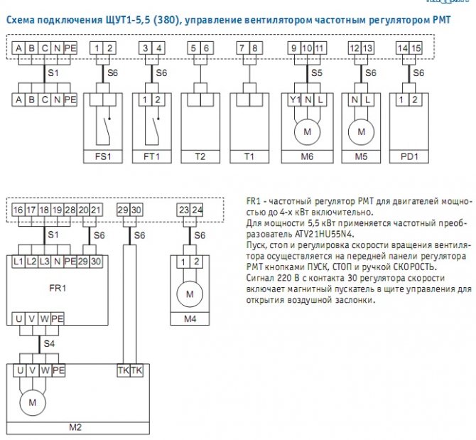
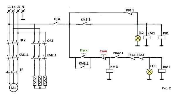
Ventilation control cabinet diagram
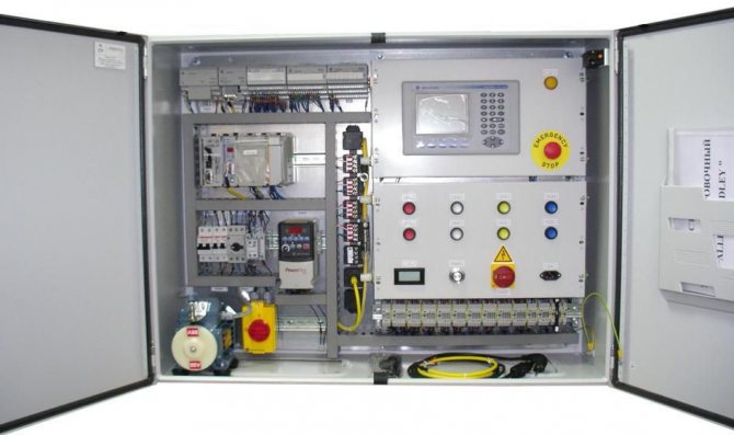
The ventilation control cabinet is arranged as follows:
- Private converter.
- Multiprocessor controller.
- Switch.
- Actuator.
- Automatic machines.
- Contactor.
- Defense mechanisms.
- Relay.
- Indicators.
Light and sound indicators provide control over the operation of the entire ventilation system of the room. The relay controls electrical circuits, opens and closes them. The contactor allows you to control the system using the remote control. The automata implement the flow of current into the electrical circuit. Starters for starting, a switch for disconnecting equipment in the cabinet. A multiprocessor pixel controller is often used to operate the memory card. The choice of the mode for a smooth start of the engine and a gradual increase in the rotation of the fan blades is carried out by a private converter.
We recommend that you familiarize yourself with: Varieties and arrangement of ventilation ducts
Elements of ventilation systems
The control system includes basic elements such as sensors, regulators and other actuators.
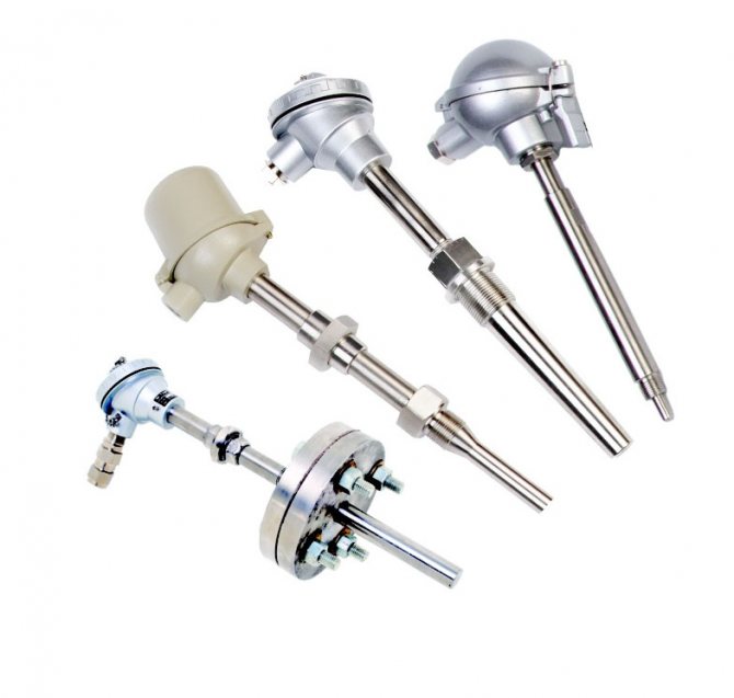
Sensors
With the help of sensors, you can receive information about the state of the required object by various parameters (temperature, pressure, humidity, etc.) and monitor it in the event of the slightest system failure.The sensors must be selected strictly in accordance with the conditions of a particular ventilation (operating conditions, range and degree of measurement accuracy, etc.).
Temperature sensors are made for outdoor and indoor use, they can show the temperature on the surface of the pipeline or inside the channel (air duct). They are fixed either on the pipes themselves (on their surface) - external, or perpendicular to the moving air flow in the pipe, duct - channel sensors. Atmospheric sensors are installed outside the building, above its middle, on the leeward side, and room types of sensors should be mounted indoors, at a distance of at least 1 - 1.5 m from the floor.
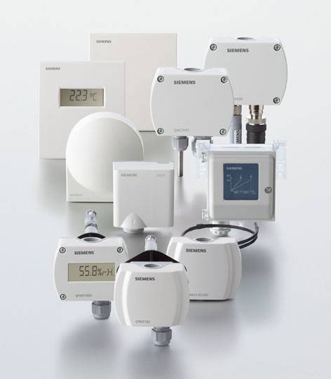
Ventilation and heating system sensors
Ventilation control also depends on sensors that regulate the degree of humidity, they are for indoor and duct purposes. Outwardly, they look like a unit with a built-in electrical device that measures the relative humidity of the air and converts the received data into electronic signals. For the device to work more accurately, it must be installed at a certain distance from windows, heating devices, ventilation jets and sunlight.
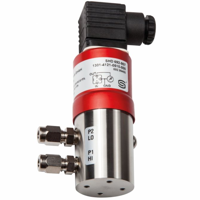
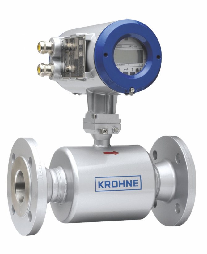
Flow sensors are devices that measure the speed of flow (it can be both liquid and gas) in pipes and air ducts. The calculation of the gas or liquid flow rate is carried out taking into account the cross-sectional area of the pipe.
Regulators
Regulators are required to control the executive ventilation mechanisms. They receive signals from sensors, process their readings and activate the actuators of the ventilation system.
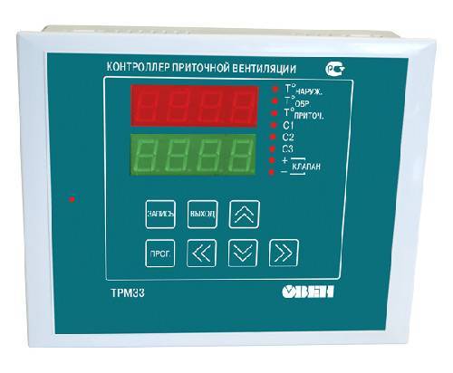
Regulators for control of executive ventilation mechanisms
Actuators
A device that starts its work on a command received from the regulator is called an actuator. They are divided according to the way of work: electrical, mechanical, hydraulic, etc.
All processes that make up the entire ventilation control system are controlled by a device such as an electrical control panel.
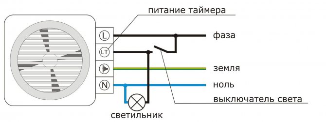
Exhaust fan connection diagrams
Connection diagram of the exhaust fan in the bathroom The connection of the fan in the bathroom is carried out in accordance with different schemes. Excess foam is trimmed and the space around the pipe is leveled with a putty.
Very often, many consumers use a single light source that works from a common switch. Through automation Recently, in the struggle for a buyer, manufacturers began to supply their devices with automation elements - timers and humidity sensors.
Replace the protective cover and put on the key. If the bathroom is combined with a bathroom, then an unpleasant odor and various microbes in the form of fungus and mold may appear, which have a negative effect on human health and life.
Another way is to install a silencer directly behind the fan. Fan connection diagram To connect the ventilation device, several of the simplest and most accessible schemes are used.
An important feature is not only the technical characteristics, country of origin, but also the design of the device.
After completing all the work, it is necessary to check the operation of each device in the bathroom. When using a separate switch to turn on the fan, the following wire commutation must be done: The neutral wire of the ventilation device must be connected to the neutral wire of the network. If the match continues to burn and the flame does not react to the exhaust grille, then it is necessary to clean the ventilation ducts and install a fan. Fan connection