Home / Boiler houses
Back to
Published: 28.02.
Reading time: 6 minutes
0
518
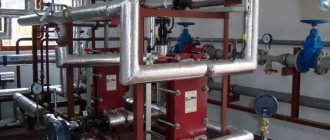
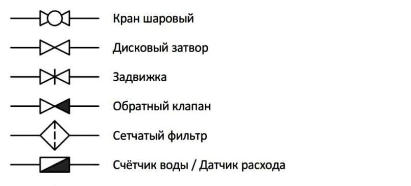
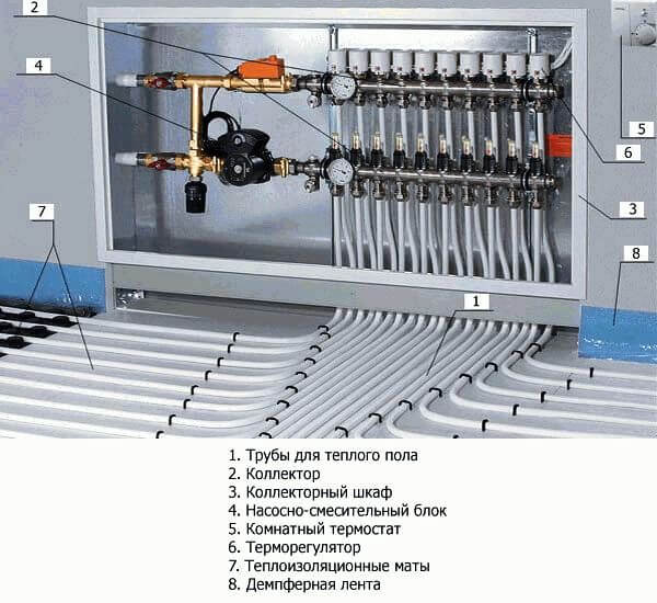
The thermal diagram of the boiler room is intended for the graphic representation of the main and auxiliary equipment, and the relationship with the help of engineering networks. Such schemes are mandatory in the development of design documentation, they are performed using elements approved by SNIP.
The diagram shows the flow of the coolant through the pipes to the heating devices, the boiler, the tank and the pump. The lines indicate the location of control valves and safety devices.
- 1 What is the difference between basic and detailed thermal diagrams
- 2 What is the difference between circuits with a closed and open system
- 3 Boiler room diagram when using solid fuel
- 4 Electric boiler plan
- 5 Diagram with a gas boiler
- 6 Boiler in the boiler room diagram
- 7 Harness with a hydraulic arrow
- 8 Boiler room layout with 2 boilers
What is the difference between basic and detailed thermal diagrams
Thermal heat supply schemes are principle, detailed and installation. On the basic diagram of the boiler room, only the main heat-and-power equipment is indicated: boilers, heat exchangers, deaeration plants, filters for chemical water treatment, feed, make-up and drainage centrifugal pumps, as well as engineering networks that combine all this equipment without specifying the number and location. On such a graphic document, the costs and characteristics of the heat transfer fluids are indicated.

The expanded thermal diagram reflects the placed equipment, as well as the pipes with which they are connected, with the specification of the location of the shut-off and control valves, safety devices. In the case when the application of all nodes to the expanded thermal diagram is impossible, then such it is disconnected into its constituent parts according to the technological principle. The technological scheme of the boiler house provides detailed information on the installed equipment.
https://youtu.be/YX_xHpyyW4g
Designing a boiler room in a private house: general provisions
The heat supply system operates around the clock for almost 7-8 months, “burning” tens of thousands of rubles in the boiler furnaces. Therefore, all homeowners strive to optimize the performance of the system. Moreover, an accurate calculation of the thermal schemes of hot-water boiler houses, carried out at the design stage, will help to strengthen the reliability of the structure and reduce the energy consumption of heating devices.
To do this, you just need to calculate the options for placing the boiler, expansion tank, additional heater, along the way, having decided on the features of the wiring and the nuances of circulation.
That is, you need to draw up a boiler room project, consisting of the following documents:
Basic thermal diagram of a hot water boiler house
- Layouts of all components of the system in the house itself. This document will come in handy at the stage of pipeline installation.
- Layouts of heating devices, pumps, expansion tanks and other equipment. This document during the assembly of the water heating and heating branches of the hot water boiler house.
- Specifications for all system components. This document is used in the procurement of materials and equipment.
Moreover, all three documents can be accommodated on one schematic diagram of the boiler house, drawn up in a simplified form (when the icons are replaced by drawings of equipment and shut-off and control valves). And further in the text we will consider several varieties of such schemes.
What is the difference between closed and open systems
The main difference between an open or gravitational heating system from a closed one is the complete absence of devices for forced movement of the coolant through the pipes. This process occurs only due to the thermal expansion of the heated liquid.
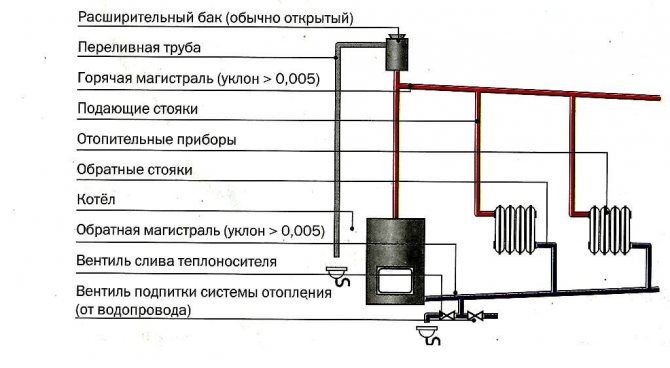
The composition of the elements in the thermal diagram of a boiler house with an open heat supply circuit:
- The heating source is a hot water boiler that runs on solid, liquid and gaseous fuels.
- Expansion tank for thermal compensation of the heat carrier.
- Temperature compensator overflow pipe.
- Supply (hot) line with heating risers.
- Heating devices.
- Return line with heating risers.
- Coolant drain valve.
- Heating network make-up valve.
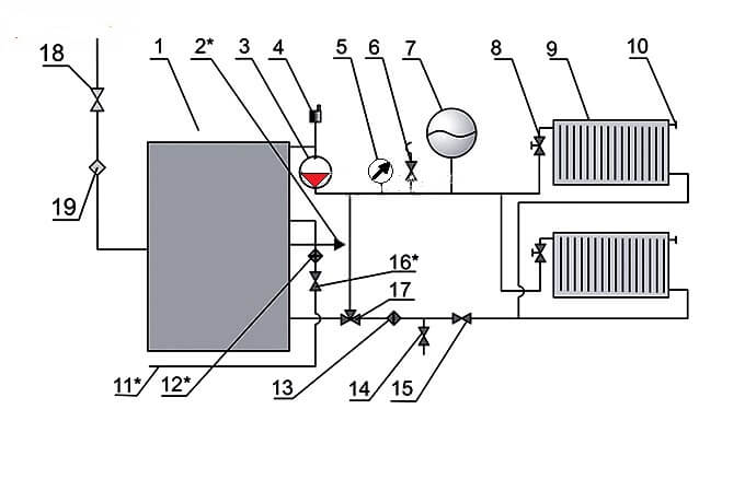
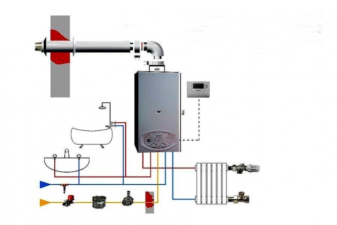
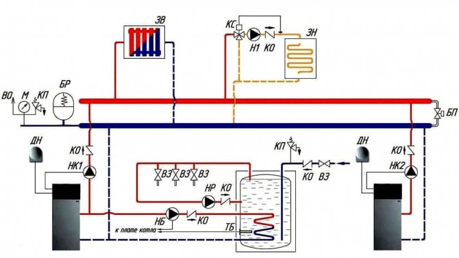
The circulation of the heating medium in the closed circuit of the boiler plant is carried out thanks to the circulation pump (3), which is installed on the water outlet line from the boiler (1), as a rule, in its upper part, and an air vent (4) is also located here. Water heated in the boiler enters the heating supply pipeline and is directed to the batteries (9) through the thermostatic valve (8).
An expansion tank (7) is installed on the supply line for temperature compensation of water during heating, a safety valve (6) to relieve the emergency pressure in the network and a manometer (5) to control the working pressure of the medium.
A Mayevsky valve is installed on the heating device for lowering the airlock (10). A three-way valve (17), a water purification filter (13), a shut-off valve (15) and a drain valve (14) are installed in the direction of the reverse movement of the coolant.
Gas is supplied to the boiler through a gas cock (18) and a filter (19) to clean the energy carrier in front of the burner nozzle. The make-up water in the hot-water boiler room scheme is supplied from the water supply (11) through the valve (16) to the filter to remove suspended solids and hardness salts. The boiler is equipped with a hot water supply line for auxiliary needs (2).
How to use the heating circuit of the boiler room
The heat supply system operates around the clock for almost 7-8 months, “burning” tens of thousands of rubles in the boiler furnaces. Therefore, all homeowners strive to optimize the performance of the system. Moreover, an accurate calculation of the thermal schemes of hot-water boiler houses, carried out at the design stage, will help to strengthen the reliability of the structure and reduce the energy consumption of heating devices.
To do this, you just need to calculate the options for placing the boiler, expansion tank, additional heater, along the way, having decided on the features of the wiring and the nuances of circulation.
Basic thermal diagram of a hot water boiler house
- Layouts of all components of the system in the house itself. This document will come in handy at the stage of pipeline installation.
- Layouts of heating devices, pumps, expansion tanks and other equipment. This document during the assembly of the water heating and heating branches of the hot water boiler house.
- Specifications for all system components. This document is used in the procurement of materials and equipment.
Moreover, all three documents can be accommodated on one schematic diagram of the boiler house, drawn up in a simplified form (when the icons are replaced by drawings of equipment and shut-off and control valves). And further in the text we will consider several varieties of such schemes.
Typical boiler room layout
- An open variety, when warm liquid is drawn from "local" installations.
- Closed version, when the heating system coolant is also used to heat water.
Moreover, the open circuit assumes additional energy consumption for powering the "local" water heating installation, but it is cheaper at the installation stage. The closed circuit of the boiler room of a private house is more difficult to install, but it is "powered" from a central boiler.Moreover, due to heat pumps and intermediate evaporators and condensers, liquid of practically drinking quality, heated to 70-100 degrees Celsius, is discharged into the hot water supply system.
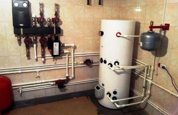
Therefore, as a diagram of a water heating boiler room, in most cases, it is a closed version, consisting of the following units, is used:
- The main boiler, which heats water for the heating system and the water heating circuit.
- The water heating circuit itself, circulating inside the storage tank.
- The circuit of the hot water supply system, closed to the storage tank.
As a result, the storage tank works like an ordinary battery that heats not the room, but the hot water supply system. That is, we have in front of us a slightly unusual storage boiler.
The system of open running hot water supply operates on the basis of a double-circuit boiler, which passes through a heated coil either a portion of water from the heating system or water from the hot water supply system. That is, the open circuit turns the heating system boiler into an ordinary column. Moreover, the best option for an open water heating installation is a boiler with two spirals located in separate combustion chambers.
Automated boilers are cheaper to operate than conventional heating devices. After all, a standard device operates in one mode around the clock, while a "smart" boiler is equipped with a special device that synchronizes the boiler operation with the needs of the owners of the house.
Boiler room automation scheme
- Optimizes the heating temperature depending on the season. After all, in summer it is more pleasant to use warm water, and in winter, a truly hot liquid must circulate in the SGW.
- They control the operation of the "circuits" of the heating and water heating boiler. After all, most models are equipped with only one "combustion chamber". That is, either the heating or water heating branch is in working order.
- They control the temperature regimes of not only the water heater, but also the heating unit. After all, day and night modes should be used on both the heating and water heating branches.
- Correct the operation of pumps and circulation and / or recirculation systems in a closed circuit. Moreover, without this function, the operation of a closed water heating system is not possible in principle. That is, there is a certain set of microcircuits or mechanical control elements in any closed circuit of a water heating boiler.
Moreover, the automatic control unit can operate in three modes, namely:
- In the format of the priority of the hot water system. That is, when all the power goes to the water heating circuit. Usually this mode is used during the warm season.
- In mixed operation format, when either the heating branch or the water heater is operating. This mode is maintained with flowing water heating, carried out in an open circuit.
- In the format of work without priorities, when most of the energy goes to the heating circuit, and some is spent on heating water. This control option is recommended for closed water heating systems.
Of course, all of the above modes can be implemented even in a single device format. Therefore, a water heating system using a boiler can be implemented in a flow-through format (direct heating of an open type in a double-circuit boiler) or in an accumulative format (indirect heating of a closed type in an expansion tank).
This feature of water heating boilers makes it possible to save energy both in winter and in summer. Indeed, in the cold season, you can use indirect heating from the steam line located in the tank. And in the warm season, you can draw hot water directly from the heating circuit of the boiler.
Requirements for boiler rooms are set out in SNiP.Depending on the place where the room with the heating equipment installed in it is located, boiler rooms can be attributed to one of the following types:
- built-in;
- freestanding;
- attached.
Read next: Drywall niches in the living room 17 photos
The dimensions of the room allocated for the boiler room are selected based on the type of fuel and the design of the boiler.
When arranging a special room for a boiler room is difficult, there is another option - a mini-boiler room. It is placed in a special container that can be placed in the yard of the house. It remains only to connect the mini-boiler room to the communications.
A mini-boiler room in the courtyard next to the mansion saves you from design work, the construction and arrangement of a separate room, ventilation devices. The container already contains everything you need for the efficient functioning of the heating system
The low popularity of such modules is explained by their rather high cost. If there is a prospect of allocating space for a boiler room in the basement, you can buy the equipment separately. Then the heating system will be much cheaper.
A significant part of the family budget is spent on heating a house. Therefore, at the design stage of the system, one should strive for its maximum optimization by performing an accurate calculation of the boiler room scheme for suburban housing. It will require a miscalculation of all options for the location of equipment, including a boiler, an expansion tank, radiators, as well as taking into account the features of wiring and circulation.
When designing a boiler room, it is necessary to proceed from the requirements of regulatory documents. In the room where the boiler is installed, additional heating is often installed, since the heat generated by the unit itself is not enough
In a well-designed schematic diagram of the boiler room, all elements and the pipeline connecting them should be reflected. The standard drawing includes: boilers, pumps - feed, network, circulation, recirculation, tanks - condensing and storage, heat exchangers, fans, fuel supply and combustion devices, control panels, heat shields, water deaerator.
When drawing up a typical boiler room scheme, one of two options for heating networks can be taken as a basis - open and closed. Installation of an open circuit is less costly, but more expensive during operation. The second option is more complicated at the initial stage, but the coolant leakage is practically reduced to zero, since the system is hermetically sealed. This scheme is used in most private houses.
The closed system includes a boiler that provides both the heating system and the water heating circuit with hot coolant, and a closed hot water supply pipeline. The circulation of the coolant is carried out here forcibly by means of a pump. This allows, when installing pipes, not particularly worrying about slopes, to lay them as more conveniently.
- A maximum of 2 boilers can be installed in one room, whatever its area.
- During the construction and decoration of the boiler room, it is unacceptable to use materials that do not meet fire safety requirements. For the construction of walls, it is necessary to use bricks or concrete blocks, and in the form of finishing - plaster or tiles. The floor must be covered with concrete or metal.
- Ventilation and chimney must be suitable for the installed equipment. Special requirements are imposed on ventilation when using gas-powered equipment. In any case, the air in the room must be circulated and renewed at least 3 times within 60 minutes.
- A prerequisite is the presence of a window and a door that opens outward. There may be a second door leading to the utility room, but it must be completed in accordance with the fire safety conditions.
The area of the boiler room should be calculated based on the characteristics of the equipment that is planned to be installed and taking into account additional square meters for convenient maintenance. There are a number of additional requirements for the premises and equipment of boiler rooms, depending on the decision made regarding the type of fuel.
Boiler room diagram when using solid fuel
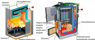
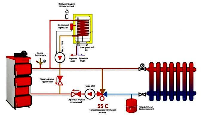
Solid fuel boilers have a certain drawback, which is caused by the high inertia of operation, due to the impossibility of fine adjustment of the solid fuel combustion process.
In order to smooth out the deficiency, a buffer tank is installed in the circuit, which picks up the temperature to heat the heating circuit and consumes heat for a long time.
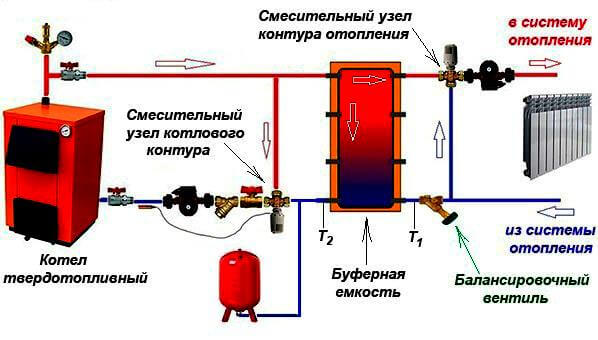
Such a thermal diagram of a solid fuel boiler house consists of:
- Heat supply source with primary heating circuit: solid fuel boiler;
- safety group with safety valve;
- buffer capacity;
- heating circuit circulation pump;
- boiler circulation pump;
- expansion tank;
- shut-off valves, drains, air vents;
- balancing valve;
- mixing unit of the heating circuit, for automatic maintenance of the temperature in the batteries;
- mixing unit of the boiler circuit, for optimal boiler operation;
- weather-dependent or customizable automation with emergency mode signaling.
General characteristics of boiler rooms.A boiler plant is an installation consisting of one or more boilers and auxiliary equipment (systems). The main equipment of the boiler houses are steam and hot water boilers. To ensure the normal operation of the boilers, auxiliary equipment is used, which, according to its purpose, is combined into the following systems:
- fuel facilities for receiving, storing and supplying fuel to boilers;
- draft system providing air supply to boilers for fuel combustion and removal of combustion products into the atmosphere;
- a water treatment system that purifies water from mechanical impurities, salts - scale-forming agents and corrosive gases;
- safety automation system and automatic regulation, control, signaling and control of technological processes;
- equipment power supply system and boiler room lighting, etc.
Depending on the nature of heat loads, boiler houses are divided into:
- heating, generating heat for heating systems, ventilation and hot water supply of buildings and structures;
- heating and production, generating heat for heating systems, ventilation, hot water supply and technological purposes;
- industrial, generating heat for technological purposes.
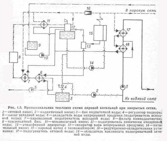
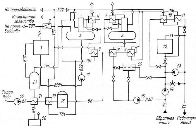
Thermal diagram of a boiler room with steel steam boilers. In fig. 25, a thermal diagram of a heating and industrial boiler house with steam boilers is given, since for technological purposes wet saturated steam with a pressure of 0.9 MPa is required. For the sake of simplicity, one boiler is shown in the diagram.
Steam from boiler 1 enters the collecting steam line. Some of the steam is used in production (arrow with the word “steam”). Another part of the steam is consumed in the boiler room to heat the heating water in the water heaters 5 and 6. The network water is supplied to the water heaters by the network pump 7. Before the steam-water heater 4, the steam pressure is reduced to 0.6 - 0.7 MPa in the reduction unit 3. Steam in the water heater 4 gives off its heat to the heating water and turns into condensate. The condensate is cooled down to 80 - 85 ° C in the condensate cooler 5. From it, the condensate flows by gravity to the deaerator 11. The condensate from the production is collected in the condensate tank 8 and is pumped by the pump 9 into the deaerator.
Losses of water, steam and condensate are replenished by the supply of raw water from the water supply by pump 19.The pump pumps water through the steam-water heater 17, where its temperature increases from 5-10 to 20-30 ° C. Water heating prevents the formation of condensate on pipelines and on chemical water treatment equipment 16.
Chemical water treatment is designed to reduce water hardness to standard values. Further, the softened water enters the deaerator 11 to remove oxygen and carbon dioxide from it. Degassing of water and condensate occurs during boiling at a pressure of 0.12 MPa and a boiling point of 104 ° C.
The finally treated water from the deaerator is supplied to feed pumps 12 and 13 and a feed pump 10. Feed pump 13 is operational and has an electric drive. The pump 10 feeds the heating network with water to maintain the specified static pressure in the network.
In the absence of electricity, the boiler house is idle, but the boilers continue to generate steam due to the accumulated heat. Therefore, in boilers it is necessary to maintain the required water level in order to prevent overheating of the heating surfaces. For this purpose, a steam driven pump 12 (steam pump) is used.
To prevent the formation of scale, the salts dissolved in the boiler water are continuously removed from the boiler with water, which is called blowdown water. To recover the heat and mass of blowdown water, a continuous blowdown separator 20 and a blowdown water cooler (heat exchanger) 15 are used.
The pressure in the separator is at the level of 0.2 MPa, and in the boiler 0.8 - 1.4 MPa. Due to a sharp drop in water pressure in the separator, the water instantly boils and partially (up to 10%) turns into steam. Part of the heat of the water is used for the formation of steam, and therefore the temperature of the blowdown water is reduced by 50 - 70 ° C and at the outlet from the separator has a temperature of about 120 ° C.
Further, this water is cooled in a heat exchanger 15 to 60–40 0С, heating raw water in it. After the heat exchanger, the blowdown water is not used in the boiler room and is discharged into the blowdown well 18. Periodic blowdown water of the boilers, which removes sludge from them, goes directly to the blowdown well. Other waste water and condensate streams can also enter here.
If the temperature of the water mixture in the well exceeds 60 ° C, then it is diluted with cold tap water and discharged into the sewerage system.
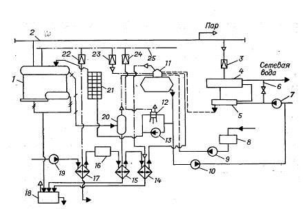
Fig. 25. Basic thermal diagram of a boiler room with steel steam boilers:
1 - boiler; 2 - main steam line; 3 - reduction unit; 4 - steam-water heater; 5 - condensate cooler; 6 - jumper; 7 - network pump; 8 - condensate tank; 9 - condensate pump; 10 - make-up pump; 11 - deaerator; 12 - steam feed pump; 13 - electrically driven feed pump; 14 - vapor cooler; 15 - blowdown water cooler; 16 - HVO; 17 - raw water heater; 18 - purge well; 19 - raw water pump; 20 - separator for continuous blowdown; 21 - economizer; 22, 23, 24 - pressure reducing valve; 25 - steam line for auxiliary needs.
For heating the water before the cold water treatment plant, for the operation of the deaerator and the steam pump, the auxiliary steam line 25 is used. The steam pressure in it is the same as in boilers, and therefore reducing valves 22 - 24 are used to reduce the steam pressure for auxiliary needs. For example, in the deaerator steam must be supplied with a pressure of the order of 0.15 MPa, since the working pressure in the deaerator is 0.12 MPa.
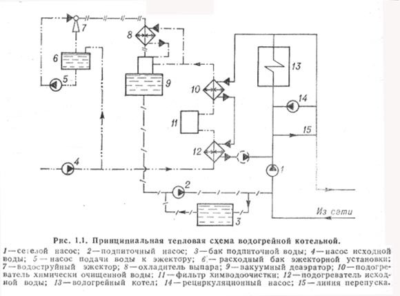
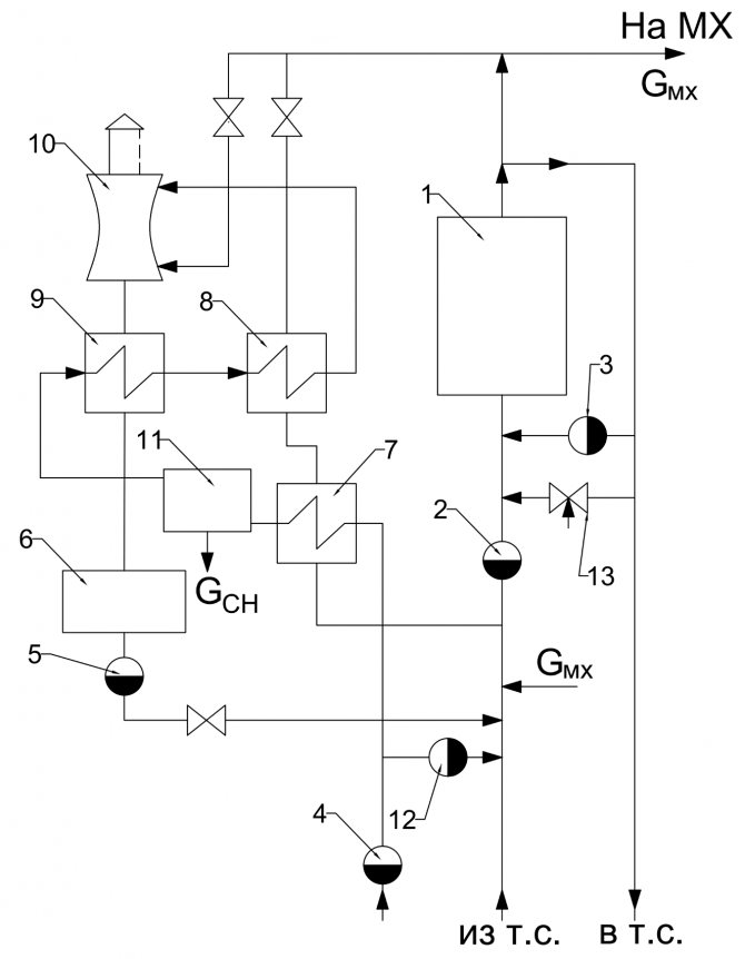
Thermal diagram of a boiler room with steel hot water boilers. In fig. 26 shows a thermal diagram of a boiler room with two steel hot water boilers, which provides heat to an open heat supply system.
The return network water by the network pump 6 is pumped through the hot water boilers, heats up in them to the required temperature and enters the supply pipeline of the heating network. The temperature of the supply water can be regulated by mixing the return water into the supply pipeline via jumper 3.
To reduce the corrosion of the heating surfaces of boilers with condensate of sulfuric acid vapors contained in the combustion products, the water at the inlet to the boilers must have a temperature of at least 70 ° C. The water is heated with hot water supplied by the recirculation pump 2 to the inlet of the boilers.
The raw water is softened in the HVO unit 9 and degassed in the deaerator 11. Due to the lack of steam, a vacuum deaerator is used, in which boiling water has a temperature of 70 - 80 ° C at a pressure of 0.03 - 0.04 MPa.
The softened and deaerated water by the pump 12 is pumped into the storage tank 13, from which the heating network is fed.
Fig. 26... Thermal diagram of a boiler room with steel hot water boilers:
1 - boiler; 2 - recirculation pump; 3 - jumper; 4 - supply pipeline; 5 - return pipeline; 7 - raw water pump; 8 - heater; 9 - HVO; 10 - heater; 11 - deaerator; 12 - transfer pump; 13 - storage tank; 14 - make-up pump.
Electric boiler plan
An electric boiler is a unit that heats a coolant by converting electricity into thermal energy. It is used as a source of heat supply for small suburban houses or as an emergency source with a gas or solid fuel boiler.
Based on the modification of such devices, various schemes for connecting electric boilers to heating are used. The most popular is a multi-level heating system with a combination of heating devices in the form of radiators and a "warm floor" system.
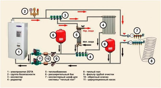
Basic elements of electric heating of a private house:
- Heating source, electric boiler.
- Safety group with air vent, safety valve and pressure gauge to relieve excess pressure in the network.
- Collector for directing water along the contours.
- Radiators.
- Heat exchanger for hot water supply.
- Expansion tank for hydraulic compensation of the system.
- Collector for the "warm floor" system.
- Underfloor heating system.
- Filter for cleaning the coolant from suspended solids.
- Check valve.
- Circulating electric pump.
- Power supply networks.
- Security automation with alarm.
Gas boiler circuit
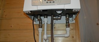
Gas boilers are the most economical and functional heating sources. A small building, in fact, houses a mini-boiler room in a private house.
Manufacturers of modern boilers equip all the necessary equipment in the body in the form of pumps, an expansion tank, a safety relief valve and an air vent. The owner of such equipment only needs to connect the unit to the heating and hot water supply circuit, which significantly reduces installation costs.
But the main advantage of the integrated boiler assembly is the consistency of the operation of all auxiliary units that have been tested and adjusted at the factory.
The simplest thermal diagram of a gas boiler house:
- The heat supply source is a gas boiler.
- Safety group, with air vent, safety valve, pressure gauge and expansion tank.
- Coolant supply to heating devices.
- Coolant return from heating devices
- Heating radiators
- Supply of tap water for replenishment of the heating network with a filter and shut-off and safety valves.
- Supply of tap water to the DHW circuit of the boiler.
- Filter for coarse cleaning of the coolant from suspended solids on the return line.
- Non-return valve on the return line.
- Circulation pump on the return line.
Typical projects
Typical projects
Boiler houses are very popular in our country and today they successfully heat both small private buildings and huge industrial facilities. These are municipal buildings, and various educational institutions - clinics, hospitals, schools, institutes and universities, kindergartens and schools, factories and plants, cafes and restaurants, shopping malls.
Typical boiler house project
In the construction of boiler houses, the moment of design is very important. Today there are standard projects that are allowed for construction.
Any one consists of one or more boilers, burners, a boiler, an automatic control box with sensors, pumps, a gas pipe with valves and other elements and devices that will ensure the normal operation of the boiler room.
Each of these elements is necessary and important, and their quantity and quality depends on the type of boiler room and the manufacturer. By type of fuel, boiler houses can be liquid fuel and solid fuel. In turn, these two types can be divided into many subspecies depending on the fuel that is used: diesel, coal, gas-oil, wood, etc.
There are even less powerful, but more functional boiler houses that operate on several types of fuel at the same time, while one of them will still be the main (dominant) one, and the other auxiliary.
Such boiler rooms are called combined.
Liquid fuel plants
Oil-fired boiler plants operate at large production facilities (for example, oil refineries); oil, fuel oil, diesel fuel, and diesel fuel are used as fuel.
Solid fuel plants
Solid fuel boilers often operate where it is difficult or practically impossible to use gas or liquid fuel - in remote areas of the country. As a rule, in private cottages, country houses, cottage villages. Branches and straw, firewood, coal, wood chips and other wood waste are used as fuel.
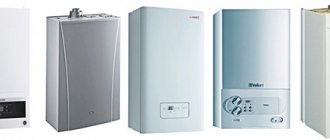
Gas boiler plants
Gas boiler plants are the most common type of boiler rooms. They work more often on natural gas, less often on liquefied hydrocarbons and associated petroleum gas. They are used to heat municipal buildings, apartment buildings, private houses and offices, warehouses and utility rooms, production facilities, old and new construction projects. By the type of execution, boiler rooms can also be placed on roof, autonomous, stationary and mobile, block-modular and frame. Execution of typical projects assumes maximum assembly of structures, and ease of installation and commissioning. This ensures a short time for completing all the necessary documentation and putting the boiler house into operation.
Boiler in the boiler room diagram
There are various options for connecting an indirect heating boiler to boilers that can operate on any type of fuel: gas, solid and liquid fuels.
In this scheme with an indirect heating boiler, a hydraulic arrow or a distribution manifold is not installed. The installation of these elements is associated with certain difficulties, since it creates a very complex hydraulic system.
This scheme uses 2 circulation pumps - for heating and hot water supply. The heating pump runs constantly when the boiler room is in operation. The DHW circulation pump is started by an electrical signal from the thermostat installed in the tank.
The thermostat detects the drop in the temperature of the liquid in the tank and transmits a signal to turn on the pump, which begins to circulate the coolant along the heating circuit between the unit and the boiler, heating the water to the set temperature.
This scheme is used for all modifications of heating sources installed in both hot water and steam boiler rooms.
A certain modification of the circuit is allowed when a low-power boiler is installed in it. The heating electric pump can be turned off by the same thermostat that turns on the pump to the boiler.
In this case, the heat exchanger heats up faster and the heating is stopped. With prolonged downtime, the temperature in the room will drop.
In addition, after the completion of heating in the boiler, the pump in the heating circuit is switched on and starts pumping cold heat carrier into the boiler, which causes the formation of condensate on the heating surfaces of the boiler and leads to its premature failure.
The condensation process can also occur in the case of long pipelines laid to the batteries. With a large heat output on heating devices, the coolant can similarly cool down very much, a low return temperature will harm the operation of the boiler.
To protect it from condensation and water hammer that occurs when cold water comes into contact with hot heating surfaces, a protective circuit equipped with a three-way valve is provided in the system.
The diagram shows a temperature of 55C. The thermostat integrated into the circuit automatically selects the required flow rate to maintain the coolant temperature at the return.
Boiler room diagram of a private house: an overview of possible options
A competently drawn up graphic drawing should first of all reflect all mechanisms, devices, apparatus and pipes connecting them
Those heating networks that operate on water are divided into two groups:
The most popular example of a schematic diagram is an example of an open-type hot water boiler house. The principle is that a circular pump is installed on the return line, it is responsible for delivering water to the boiler, and then throughout the entire system. The supply and return lines will be connected by two types of jumpers - bypass and recirculation.
The technological scheme can be taken from any reliable sources, but it would be good to discuss it with specialists. He will advise you, tell you whether it is suitable in your situation, explain the entire system of action. In any case, this is the most important structure for a private house, therefore, attention should be maximized.
The thermal diagram of boiler houses with hot water boilers has its own characteristics
And in order to be able to increase the temperature to the desired values, a recirculation pump is installed. Water boilers must be monitored so that their service life is decent, control the constancy of water consumption. Usually the manufacturer sets the minimum data for this indicator.
Read more: Site drainage design rules for the development of a drainage system
For boiler rooms to work well, you need to use vacuum deaerators. Typically, a water jet ejector will create a vacuum, and the released steam is used for deaeration. But, the main thing that they are afraid of when installing a boiler room is the constant binding to the place. Modern automation simplifies many processes.
Boiler house automation has recently become more and more in demand, because boiler automation is the most important part of a boiler plant.
There are some popular custom functions that adapt the operation of the equipment with an eye to the lifestyle of the owners of the house. This is both a conventional hot water supply system, and a set of some individual options that are convenient for these particular residents, and are economical. In the same way, you can develop a boiler room automation scheme by choosing one of the popular modes.
The charge pump must develop a high pressure higher than in the heating circuit with a relatively small flow. Still, for replenishment, pumping of large volumes of liquid is not required. The selection of such a pump is carried out according to several requirements.
When choosing, they combine the characteristics of the pump and heating networks and determine the operating point of the system
Selection of the make-up pump:
- It must create a pressure that will exceed the pressure in the CO return line;
- Also, the pressure should be able to push through the hydraulic resistance of the pressure sensor, pipeline;
- Another important criterion is the flow rate, in particular, for closed COs, the leakage rates are equal to half a percent of the volume of the coolant in the boiler and heating circuit.
At the same time, I would like to say that it is not very practical to purchase such a pump for work. In the sense that it should not only serve to recharge. It can also perform additional functions, for example, be a backup circulation pump, and also be used to pump and drain water into the circuit.
What should be in the room, what should be the schematic diagram of the boiler room of a private house on solid fuel?
Let's estimate the composition:
- The heat generator itself with accompanying bunkers, fuel tanks, etc.
- The piping of a solid fuel boiler, which includes a boiler safety group, a circulation pump and a three-way mixing valve.
- Indirect heating boiler for the production of hot water for the water supply system of the house.
- Chimney for TT boiler with effective section and height.
- Boiler water drainage system in case of preventive maintenance of the heat generator.
- Boiler automation - in-house or weather-dependent.
- Fire extinguishing system in a solid fuel boiler room.
Consider what are the features for different types of solid fuel used, what should be a boiler room for a solid fuel boiler on different types of combustion materials.
Wood-fired boiler room
Actually, a wood-fired boiler room is a classic room for a solid fuel boiler, which can have a minimum size. The main differences between different rooms are the size from the firebox door to the wall or boiler room doors. It depends on the length of the log used.
If you heat with briquettes or Euro wood, then this distance may be minimal. Do not forget that in addition to loading firewood, you still have to rake out the ash, which will also require free space in front of the firebox / ash pan.
Pellet boiler room
The size of the pellet boiler room will depend on how the pellet hopper is installed. The pellet boiler room will not only differ in floor area, but also in the height of the boiler room.
Since with a high hopper installed for 400-600 liters or with a hopper for 150-200 liters on a boiler, such as Copper, you will need more space above the hopper for loading pellets.
If the hopper is high, it is best to make a small ladder or use a low, stable ladder to load the pellets. Because it is unrealistic to lift 40 kg bags of pellets over your head for loading.
Coal-fired boiler room
The coal-fired boiler room is distinguished by the fact that it is very convenient to have a spacious coal box nearby. And not to drag coal in buckets from the shed, but to shorten the path from coal to the boiler furnace as much as possible.
In terms of size, a coal-fired boiler room will be approximately equal to a wood-fired boiler room, with the expectation that with top loading it would be good to have more space on top to wield a bucket.
Sawdust or wood waste boilers are slightly larger than conventional wood-fired heat generators. Fuel tedding systems on the grate can efficiently burn such a rapidly sintering fuel. The sawdust boiler is also distinguished by the large size of the hopper or firebox for one fuel load.
The firebox is located on top of the firebox, which means that the boiler room for sawdust or wood waste must have a higher height than a standard boiler room.
If a biofuel or husk boiler room is equipped with a pneumatic feed, then the room itself with the boiler may have small dimensions. If husk feeding with a circular agitator is used, then such a boiler house will have a large husk hopper.
And the minimum effective bunker is 2.0 x 2.0 meters. This means that the husk-based boiler room will have a minimum size of 4.0 by 4.0 meters.
In conclusion, it should be noted that the water-heating circuit of the boiler of the heating system is subject to greater corrosive loads than the heating system itself. Flue gases can damage the heat exchanger through which the heated water circulates.
Therefore, in order to neutralize the effect of catalysts for corrosive processes, the coolant at the inlet to the boiler heat exchanger must be heated to 60-70 degrees Celsius.
Read more: Summer water supply from a well options and device diagrams
However, this precaution is only justified in the case of using steel heat exchangers made of structural steel. Copper or stainless steel heat exchangers do not suffer from corrosion.
To implement the automation scheme for a private boiler house, you need to invest additional funds. A simple thermostatic valve is very inexpensive, and programmable systems are many times more expensive. Continuous operation of a conventional boiler in one mode entails a large consumption of electricity and money. Therefore, the cost of purchasing an automation unit quickly pays off during operation.
Automation in a private boiler room is a guarantee of the functioning of the heating system with maximum efficiency, which allows providing comfortable conditions for those living in the house.
The most important element of the heating system is the thermostat. Its function is to regulate the temperature both in a separate room and in the whole house. There are many types of thermostats - from simple mechanical to weather-dependent. The latter is the most technologically advanced, profitable, but also very expensive.
The heating control system consists of a temperature controller, an outside air temperature sensor, an actuator, a coolant temperature sensor, a display for connection to an external control system, a circulation pump for supplying a coolant, consumer circuits ()
The price of automation depends on the type of boiler used, on the presence of a warm floor, solar collectors, etc. In order not to spend extra money, you should analyze the features of all schemes, calculate the cost. It is quite difficult to do this on your own, but you can always turn to specialists with this problem.
Gas is an explosive substance, therefore, the requirements for gas boilers are very strict. If a boiler with a capacity of up to 30 kW is enough to heat a house, then there is no need for a separate room for the boiler room. The boiler can be placed in a well-ventilated kitchen on a wall made of non-combustible materials, provided that the volume of the room is at least 15 m2, the height from floor to ceiling is from 2.5 m2, and the floor area is from 6 m2.
Harness with a hydraulic arrow
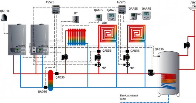
In complex multi-level heat supply systems, a hydromechanical distributor is often used to balance fluid flows in various sections of the circuit with individual circulating electric pumps - a hydraulic arrow or a manifold.
A similar scheme of the boiler unit involves the inclusion of an indirect heating boiler through the NB and HP pumps, radiator heating through the НК1 and НК2 pumps, and underfloor heating through Н1.
It has the ability to work without a hydraulic module, in which case balancing valves are provided to compensate for pressure drops in various "branches" of the system.
Complete set of thermal mechanical equipment:
- Heat supply source - 2.
- Safety group, with air vent, safety valve, pressure gauge and expansion tank.
- Coolant supply to heating devices.
- Coolant return from heating devices
- Heating radiators.
- Underfloor heating system.
- Indirect heating boiler
- Filter for coarse cleaning of boiler water from suspended solids on the return line.
- Non-return valve on the return line.
- Circulation pumps: through the main pipeline, in the underfloor heating circuit and indirect heating boiler.
Main menu
Hello, friends! The boiler plant consists of a boiler unit, which produces steam with a given pressure and temperature, and a number of auxiliary devices designed for the preparation and supply of fuel, feed water and air, as well as for the removal of industrial waste (flue gases and ash residues of fuel).
Water vapor is used in power engineering to drive steam turbines, as well as as a heating medium in technological processes (heating, drying, evaporation, etc.) and in everyday life (heating, hot water supply). Along with steam boilers in small communal boiler houses, hot water boilers are also used, in which water used for heating needs is heated.
Depending on the productivity, boiler plants are distinguished with small (up to 20 t / h), medium (20-75 t / h) and large (over 100 t of steam per hour) productivity. By the value of steam pressure, boiler plants are of low (up to ZMPa), medium (3-7.5 MPa), high (10-15 MPa), ultra-high (15-22.5 MPa) and supercritical (more than 22.5 MPa) pressure ...
There are boilers with natural and forced circulation (direct flow). In the latter, the movement of water occurs under the action of a pump. Powerful energy boilers with natural circulation, currently produced, have steam parameters p = 14 MPa and t = 570 ° C, and boilers with artificial circulation - p = 25 MPa and t = 565 ° C.
In fig. 1. shows a diagram of a screen-type boiler unit with natural circulation, which has a flare furnace for burning coal dust.
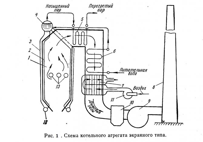
The main elements of the boiler unit are combustion chamber 1, vapor-generating heating surfaces - rows of wall tubes 2, superheater 5, water economizer 6 and air heater 7. A mixture of fuel and air is fed through burners 13 into combustion chamber 1, where the fuel is ignited and burned in suspension.
The boiler unit is continuously circulating water and steam-water mixture. The mixture of water and steam formed in the wall tubes 2 has a lower density than the water in the downpipes 3 coming from the boiler drum 4. As a result, the steam-water mixture rises through the wall tubes into the boiler drum, from where the water moves down through the unheated downpipes (natural circulation) ...
Disruption of the normal water circulation in the boiler (for example, if the water level in the boiler drum is low) can lead to overheating of the pipes and their failure. Downpipe and wall pipes are interconnected by means of a collector 12. Boiler pipes, located on the walls of the furnace, form heating surfaces, which are called screens.
In drum 4, saturated steam is separated from water, and enters the superheater 5, where it is heated to a predetermined temperature. The superheater is a heat exchanger whose tubes are bent in the form of coils. Flue gases move outside the tubes and water vapor moves inside. In large-capacity boilers, additional superheaters are installed for secondary superheating of steam.
From the superheater 5, the flue gases enter the water economizer 6, which is designed to heat the feed water supplied to the drum 4. To maintain the required water level in the boiler drum, the feed water consumption must correspond to the steam capacity of the boiler unit. Like the superheater 5, the water economizer 6 is a surface-type heat exchanger. Next, an air heater 7 is installed, in which the air supplied to the combustion chamber 1. The flue gases pass through the air heater pipes from top to bottom, and the air moves between the pipes outside in the transverse direction.
By reducing the temperature of the exhaust flue gases in the water economizer 6 and the air heater 7 to 120-200 ° C, the heat losses with the exhaust gases are reduced, which significantly increases the efficiency. boiler unit. An economizer and an air heater are installed on all units of medium and large capacity. Small capacity boilers have only a water economizer.
Heat exchange between flue gases and pipes in a water economizer and an air heater mainly occurs by convection, since at a low temperature of flue gases, the intensity of heat exchange by radiation is relatively low. Therefore, these heating surfaces are called convective. The screens 2 in the combustion chamber and the first rows of pipes of the superheater 5 are radiation heating surfaces, which, due to the high temperature of the flue gases, receive heat mainly by radiation. In direct-flow boilers, the steam-generating surfaces are a system of heated coils.
The gases carry away a significant amount of ash from the furnace (during flare combustion up to 80-90%), therefore, after the air heater 7, the flue gases are sent for cleaning to the ash collector 10, which prevents pollution of the surrounding area. Then, with the help of a smoke exhauster 9, flue gases are discharged into the atmosphere through the chimney 8. The smoke exhauster is a centrifugal fan unit with an electric drive. To supply air to the furnace of the boiler unit, a blower fan 11 is also installed.
Powerful boiler plants operating on solid fuels have a complex fuel supply and preparation system, including mills and crushers, mechanisms for feeding fuel to the combustion chamber, storage tanks for coal dust, belt conveyors, etc. The fuel preparation system can be centralized or individual. In most cases, an individual dust preparation system is used, in which each boiler has its own fuel preparation system.
Intra-boiler processes are very important during the operation of boiler plants: the formation of scale, the separation of moisture droplets from the steam that enters the superheater. A layer of scale on the inner walls of the wall and boiling pipes is a significant thermal resistance, which insulates the pipe from the steam-water mixture moving along it, which leads to dangerous overheating of the pipes. To prevent the formation of scale, the boiler unit is fed with steam condensate. Losses of condensate are usually replenished with chemically purified water, from which scale-forming salts (hardness salts) have been removed.
Various devices for mechanical separation of moisture droplets are installed inside the boiler drum. In case of poor separation, salts will enter the superheater together with moisture, which will settle on the superheater tubes. In order to prevent an increase in the concentration of salts in the boiler water, continuous blowdown of the boiler unit is used.
In this case, a part of the water is removed from the boiler drum and instead of it, the same amount of feed water is additionally supplied, containing significantly less salts. As a result, the salt content in the boiler water is kept at a certain level. Along with continuous blowing, periodic blowing is also used, in which part of the water is removed from the lower collectors 12, and with it the salts precipitated in the form of a solid precipitate (sludge).
Modern boiler units used in the power industry are very complex installations with large dimensions (their height reaches 35-50 m). The control of the operation of such boilers is automated. At the same time, steam parameters, productivity, fuel and air consumption, water level in the boiler drum, etc. are automatically maintained within the specified limits.Literature: 1) Heat engineering, under the general editorship of I.N. Sushkina, Moscow, "Metallurgy", 1973. 2) Heat engineering, Bondarev V.A., Protskiy A.E., Grinkevich R.N. Minsk, ed. 2nd, "Higher School", 1976.
Boiler room diagram with 2 boilers
The use of two gas units for one heat supply system is a fairly popular solution among owners of autonomous heating with a thermal power of the system above 50 kW.
This can be a large heated area of the object, and the presence of additional heat loads in the form of hot water or installations with air heaters.
The use of two units per one heating circuit has a number of advantages over one source of equivalent power. First of all, because several small-sized units of lower weight are much easier and more economical to place in a boiler room, which is especially important when erecting roof or semi-basement furnaces.
In addition, the installation of 2 units significantly increases the operational reliability of the heat supply system. In the event of an emergency stop of one of the units, it will continue to operate with 50% heat load.
Such a piping scheme significantly increases the working life of the boilers, due to the fact that they are less loaded during the heating season.
More about the basic diagram of the boiler room
When performing working wiring diagrams of boiler rooms, a general station or aggregate equipment layout diagram is used. In fig.
So, it is probably better to make one panel in the boiler room with a freely programmable controller, which is programmed to perform all the required actions.
Hot water boilers are equipped with steel or cast iron hot water boilers, and are designed to provide mainly housing and communal heat loads: heating, ventilation and hot air. Part of the air is supplied to the place where the fuel enters the furnace.
Further, the purge water is discharged into the sewer or enters the make-up water tank.
It can be seen from the graph that with an increase in the heat load, that is, with the opening of the DHW of the water heater, Kv monotonously increases. The reliability and efficiency of hot water boilers depends on the constancy of the water flow through them, which should not decrease relative to that set by the manufacturer. The most important of them in the assembly according to the aggregate scheme are the facilitation of accounting and regulation of the flow rate and parameters of the coolant from each unit, reducing the length of large-diameter network pipelines within the boiler room and simplifying the commissioning of each unit.
When choosing the type of burner, it is advisable to take into account the following: Gas distribution networks and gas consumption networks operating under pressure of natural gas or liquefied petroleum gas up to 0 MPa inclusively do not belong to hazardous production facilities. However, part of the ash in the form of liquid and pasty slag, together with unburned fuel particles, the flue gases are captured and removed from the combustion chamber. Boiler room schemes with a heat accumulator
See also: Energy survey of facilities