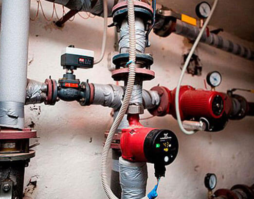
Selection of a circulation pump for the heating system. Part 2
The circulation pump is selected for two main characteristics:
- G * - consumption, expressed in m3 / h;
- H is the head, expressed in m.
- the amount of heat that is needed to compensate for heat losses (in this article, we took a house with an area of 120 m2 with a heat loss of 12,000 W as a basis)
- specific heat capacity of water equal to 4200 J / kg * оС;
- the difference between the initial temperature t1 (return temperature) and the final temperature t2 (flow temperature) to which the coolant is heated (this difference is denoted as ΔT and in heat engineering for calculating radiator heating systems is determined at 15 - 20 ° C).
* Manufacturers of pumping equipment use the letter Q to record the flow rate of the heating medium. Manufacturers of valves, for example, Danfoss uses the letter G to calculate the flow rate.
In domestic practice, this letter is also used.
Therefore, within the framework of the explanations of this article, we will also use the letter G, But in other articles, going directly to the analysis of the pump operation schedule, we will still use the letter Q for the flow rate.
Determination of the flow rate (G, m3 / h) of the heat carrier when choosing a pump
The starting point for selecting a pump is the amount of heat that the house loses. How to find out? To do this, you need to calculate the heat loss.
This is a complex engineering calculation that requires knowledge of many components. Therefore, within the framework of this article, we will omit this explanation, and we will take one of the common (but far from accurate) techniques used by many installation firms as the basis for the amount of heat loss.
Its essence lies in a certain average loss rate per 1 m2.
This value is arbitrary and amounts to 100 W / m2 (if the house or room has non-insulated brick walls, and even insufficient thickness, the amount of heat lost by the room will be much greater.
note
Conversely, if the building envelope is made using modern materials and has good thermal insulation, heat loss will be reduced and can be 90 or 80 W / m2).
So, let's say you have a house of 120 or 200 m2. Then the amount of heat loss agreed by us for the whole house will be:
120 * 100 = 12000 W or 12 kW.
What does this have to do with the pump? The most direct.
The process of heat loss in the house occurs constantly, which means that the process of heating the premises (compensation for heat loss) must go on constantly.
Imagine that you have no pump, no piping. How would you solve this problem?
To compensate for the heat loss, you would have to burn some kind of fuel in a heated room, for example, firewood, which, in principle, people have been doing for thousands of years.
But you decided to give up firewood and use water to heat the house. What would you have to do? You would have to take a bucket (s), pour water in there and heat it over a fire or gas stove to boiling point.
After that, take the buckets and carry them to the room, where the water would give its warmth to the room. Then take other buckets of water and put them back on the fire or gas stove to heat the water, and then carry them into the room instead of the first.
And so on ad infinitum.
Today the pump does the job for you. It forces the water to move to the device, where it heats up (boiler), and then, to transfer the heat stored in the water through pipelines, directs it to heating devices to compensate for heat losses in the room.
The question arises: how much water is needed per unit of time, heated to a given temperature, to compensate for the heat loss at home?
How to calculate it?
To do this, you need to know several values:
These values need to be substituted into the formula:
G = Q / (c * (t2 - t1)), where
G - required water consumption in the heating system, kg / sec. (This parameter should be provided by the pump. If you buy a pump with a lower flow rate, then it will not be able to provide the amount of water required to compensate for heat losses; if you take a pump with an overestimated flow rate, this will lead to a decrease in its efficiency, excessive consumption of electricity and high initial costs);
Q is the amount of heat W required to compensate for heat loss;
t2 is the final temperature to which you need to heat the water (usually 75, 80 or 90 ° C);
t1 - initial temperature (temperature of the coolant cooled by 15 - 20 ° C);
c - specific heat capacity of water, equal to 4200 J / kg * оС.
Substitute the known values into the formula and get:
G = 12000/4200 * (80 - 60) = 0.143 kg / s
Such a flow rate of the coolant within a second is necessary to compensate for the heat losses of your house with an area of 120 m2.
Important
In practice, use is made of a flow rate of water displaced within 1 hour. In this case, the formula, after going through some transformations, takes the following form:
G = 0.86 * Q / t2 - t1;
or
G = 0.86 * Q / ΔT, where
ΔT is the temperature difference between supply and return (as we have already seen above, ΔT is a known value that was initially included in the calculation).
So, no matter how complicated, at first glance, the explanations for the selection of a pump may seem, given such an important quantity as flow, the calculation itself and, therefore, the selection by this parameter is quite simple.
It all comes down to substituting known values into a simple formula. This formula can be “hammered in” in Excel and use this file as a quick calculator.
Let's practice!
A task: you need to calculate the flow rate of the coolant for a house with an area of 490 m2.
Decision:
Q (amount of heat loss) = 490 * 100 = 49000 W = 49 kW.
The design temperature regime between supply and return is set as follows: supply temperature - 80 ° C, return temperature - 60 ° C (otherwise, the record is made as 80/60 ° C).
Therefore, ΔT = 80 - 60 = 20 ° C.
Now we substitute all the values into the formula:
G = 0.86 * Q / ΔT = 0.86 * 49/20 = 2.11 m3 / h.
How to use all this directly when choosing a pump, you will learn in the final part of this series of articles. Now let's talk about the second important characteristic - pressure. Read more
Part 1; Part 2; Part 3; Part 4.
Specific calculations
Let's say you need to make a calculation for a household with an area of 150 sq. m. If we assume that 100 watts of heat are lost per 1 square meter, we get: 150x100 = 15 kW heat losses.
How does this value compare with a circulation pump? With heat losses, there is a constant consumption of heat energy. To maintain the temperature in the room, more energy is needed than to compensate for it.

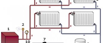
To calculate a circulation pump for a heating system, you should understand what functions it has. This device performs the following tasks:
- create a water pressure sufficient to overcome the hydraulic resistance of the system components;
- pump through pipes and radiators such a volume of hot water that is required to effectively warm up the household.
That is, in order for the system to work, you need to adjust the heat energy to the radiator. And this function is performed by a circulation pump. It is he who stimulates the supply of coolant to heating devices.
The next task: how much water, warmed to the required temperature, must be delivered to the radiators in a certain period of time, while compensating for all heat losses? The answer is expressed in the amount of pumped heat carrier per unit of time. This will be called the power that the circulation pump has. And vice versa: you can determine the approximate flow rate of the coolant by the pump power.
The data that is needed for this:
- The amount of heat energy required to compensate for heat loss. For this household with an area of 150 sq. meters this figure is 15 kW.
- The specific heat capacity of water, which acts as a heat carrier, is 4200 J per 1 kilogram of water, for each degree of temperature.
- Delta of temperatures between the water at the supply from the boiler and at the last section of the pipeline in the return.
It is believed that under normal conditions this last value does not exceed 20 degrees. On average, they take 15 degrees.

The formula for calculating the pump is as follows: G / (cx (T1-T2)) = Q
- Q is the consumption of the heat carrier in the heating system. So much liquid at a certain temperature must be delivered to the circulation pump to the heating devices per unit of time so that heat losses are compensated. It is impractical to purchase a device that has more power. This will only lead to increased electricity consumption.
- G - heat loss at home;
- T2 is the temperature of the coolant flowing out of the boiler heat exchanger. This is exactly the temperature level that is needed to heat the room (approximately 80 degrees);
- T1 is the temperature of the coolant in the return pipeline at the entrance to the boiler (most often 60 degrees);
- c is the specific heat of water (4200 Joules per kg).
When calculated using this formula, the figure is 2.4 kg / s.
Now you need to translate this indicator into the language of the manufacturers of circulation pumps.
1 kilogram of water corresponds to 1 cubic decimeter. One cubic meter is equal to 1000 cubic decimeters.
It turns out that the pump pumps water in the following volume per second:
- 2.4 / 1000 = 0.0024 cubic meters m.
Next, you need to convert seconds to hours:
- 0.0024x3600 = 8.64 cubic meters m / h.
Determination of the estimated flow rates of the coolant
The estimated consumption of heating water for the heating system (t / h) connected according to a dependent scheme can be determined by the formula:
Figure 346. Estimated consumption of heating water for CO
- where Qо.р. is the estimated load on the heating system, Gcal / h;
- τ1.p. is the temperature of the water in the supply pipeline of the heating network at the design temperature of the outside air for the design of heating, ° С;
- τ2.r.- the temperature of the water in the return pipe of the heating system at the design temperature of the outside air for the design of heating, ° С;
The estimated water consumption in the heating system is determined from the expression:
Figure 347. Estimated water consumption in the heating system
- τ3.r.- the temperature of the water in the supply pipeline of the heating system at the design temperature of the outside air for the design of heating, ° С;
Relative flow rate of heating water Grel. for the heating system:
Figure 348. Relative flow rate of heating water for CO
- where Gc. is the current value of the network consumption for the heating system, t / h.
Relative heat consumption Qrel. for the heating system:
Figure 349. Relative heat consumption for CO
- where Qо.- current value of heat consumption for the heating system, Gcal / h
- where Qо.р. is the calculated value of the heat consumption for the heating system, Gcal / h
Estimated flow rate of the heating agent in the heating system connected according to an independent scheme:
Figure 350. Estimated CO consumption according to an independent scheme
- where: t1.р, t2.р. - the calculated temperature of the heated heat carrier (second circuit), respectively, at the outlet and inlet to the heat exchanger, ºС;
The estimated flow rate of the coolant in the ventilation system is determined by the formula:
Figure 351. Estimated flow rate for SV
- where: Qv.r.- the estimated load on the ventilation system, Gcal / h;
- τ2.w.r. is the calculated temperature of the supply water after the air heater of the ventilation system, ºС.
The estimated flow rate of the coolant for the hot water supply (DHW) system for open heat supply systems is determined by the formula:
Figure 352. Estimated flow rate for open DHW systems
Water consumption for hot water supply from the supply pipeline of the heating network:
Figure 353. DHW flow from the supply
- where: β is the fraction of water withdrawn from the supply pipeline, determined by the formula:Figure 354.Share of water withdrawal from the supply
Water consumption for hot water supply from the return pipe of the heating network:
Figure 355. DHW flow from return
Estimated flow rate of the heating agent (heating water) for the DHW system for closed heat supply systems with a parallel circuit for connecting heaters to the hot water supply system:
Figure 356. Flow rate for DHW 1 circuit in a parallel circuit
- where: τ1.i. is the temperature of the supply water in the supply pipeline at the break point of the temperature graph, ºС;
- τ2.t.i. is the temperature of the supply water after the heater at the break point of the temperature graph (taken = 30 ºС);
Estimated DHW load
With battery tanks
Figure 357.
In the absence of battery tanks
Figure 358.
Heat load duration graph
To establish an economical mode of operation of heating equipment, to select the most optimal parameters of the coolant, it is necessary to know the duration of operation of the heat supply system under various modes throughout the year. For this purpose, graphs of the duration of the heat load are built (Rossander graphs).
The method for plotting the duration of the seasonal heat load is shown in Fig. 4. Construction is carried out in four quadrants. In the upper left quadrant, graphs are plotted depending on the outside temperature. tH,
heating heat load
Q,
ventilation
QB
and the total seasonal load
(Q +
n during the heating period of outdoor temperatures tn equal to or lower than this temperature.
In the lower right quadrant, a straight line is drawn at an angle of 45 ° to the vertical and horizontal axes, used to transfer the scale values P
from the lower left quadrant to the upper right quadrant. Heat load duration 5 is plotted for different outdoor temperatures
tn
by the points of intersection of the dashed lines that determine the thermal load and the duration of the standing loads equal to or greater than this one.
Area under the curve 5
the duration of the heat load is equal to the heat consumption for heating and ventilation during the heating season Qcr.
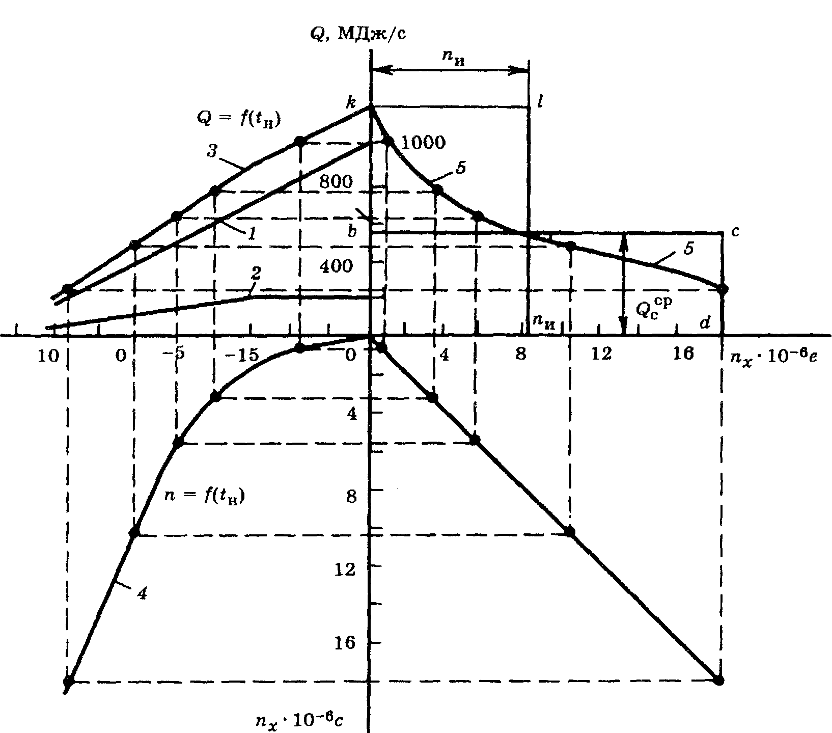
Fig. 4. Plotting the duration of the seasonal heat load
In the case when the heating or ventilation load changes by hours of the day or days of the week, for example, when industrial enterprises are switched to standby heating during non-working hours or ventilation of industrial enterprises does not work round the clock, three curves of heat consumption are plotted on the graph: one (usually a solid line) based on the average weekly heat consumption at a given outside temperature for heating and ventilation; two (usually dashed) based on the maximum and minimum heating and ventilation loads at the same outside temperature tH.
Such a construction is shown in Fig. five.
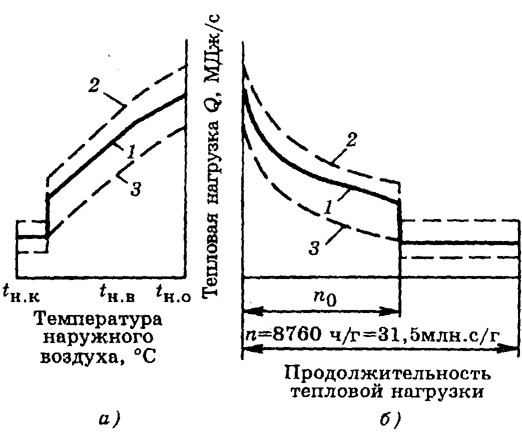
Fig. 5. Integral graph of the total load of the area
and
—
Q
= f (tн);
b
- graph of the duration of the heat load; 1 - average weekly total load;
2
- maximum hourly total load;
3
- minimum hourly total load
The annual heat consumption for heating can be calculated with a small error without accurately taking into account the repeatability of the outside air temperatures for the heating season, taking the average heat consumption for heating for the season equal to 50% of the heat consumption for heating at the design outside temperature tbut.
If the annual heat consumption for heating is known, then, knowing the duration of the heating season, it is easy to determine the average heat consumption. The maximum heat consumption for heating can be taken for approximate calculations equal to twice the average consumption.
16
Water consumption in the heating system - count the numbers
In the article, we will give an answer to the question: how to correctly calculate the amount of water in the heating system. This is a very important parameter.
It is needed for two reasons:
So, first things first.
Features of the selection of a circulation pump
The pump is selected according to two criteria:
With pressure, everything is more or less clear - this is the height to which the liquid should be raised and is measured from the lowest to the highest point or to the next pump, in the event that there is more than one in the project.
Expansion tank volume
Everyone knows that a liquid tends to increase in volume when heated. So that the heating system does not look like a bomb and does not flow along all the seams, there is an expansion tank in which the displaced water from the system is collected.
What volume should a tank be purchased or made?
It's simple, knowing the physical characteristics of water.
The calculated volume of the coolant in the system is multiplied by 0.08. For example, for a 100 liter coolant, the expansion tank will have a volume of 8 liters.
Let's talk about the amount of pumped liquid in more detail
The water consumption in the heating system is calculated using the formula:
G = Q / (c * (t2 - t1)), where:
- G - water consumption in the heating system, kg / sec;
- Q is the amount of heat that compensates for heat loss, W;
- c is the specific heat capacity of water, this value is known and is equal to 4200 J / kg * ᵒС (note that any other heat carriers have worse performance in comparison with water);
- t2 is the temperature of the coolant entering the system, ᵒС;
- t1 - temperature of the coolant at the outlet from the system, ᵒС;
Recommendation! For comfortable living, the delta temperature of the heat carrier at the inlet should be 7-15 degrees. The floor temperature in the "warm floor" system should not exceed 29
ᵒ
C. Therefore, you will have to figure out for yourself what type of heating will be installed in the house: whether there will be batteries, "warm floor" or a combination of several types.
The result of this formula will give the flow rate of the coolant per second of time to replenish the heat loss, then this indicator is converted into hours.
Advice! Most likely, the temperature during operation will differ depending on the circumstances and the season, so it is better to immediately add 30% of the stock to this indicator.
Consider the indicator of the estimated amount of heat required to compensate for heat losses.
Perhaps this is the most difficult and important criterion that requires engineering knowledge, which must be approached responsibly.
If this is a private house, then the indicator can vary from 10-15 W / m² (such indicators are typical for "passive houses") to 200 W / m² or more (if it is a thin wall with no or insufficient insulation).
In practice, construction and trade organizations take as a basis the heat loss indicator - 100 W / m².
Recommendation: calculate this indicator for a specific house in which the heating system will be installed or reconstructed.
For this, heat loss calculators are used, while losses for walls, roofs, windows, and floors are considered separately.
These data will make it possible to find out how much heat is physically given away by the house to the environment in a specific region with its own climatic regimes.
Advice
The calculated figure of losses is multiplied by the area of the house and then substituted into the formula for water consumption.
Now it is necessary to deal with such a question as the water consumption in the heating system of an apartment building.
Features of calculations for an apartment building
There are two options for arranging the heating of an apartment building:
A feature of the first option is that the project is done without taking into account the personal wishes of the residents of individual apartments.
For example, if in one separate apartment they decide to install a "warm floor" system, and the inlet temperature of the coolant is 70-90 degrees at an allowable temperature for pipes up to 60 ᵒС.
Or, conversely, when deciding to have warm floors for the whole house, one individual subject may end up in a cold apartment if he installs ordinary batteries.
The calculation of the water consumption in the heating system follows the same principle as for a private house.
By the way: arrangement, operation and maintenance of a common boiler room is 15-20% cheaper than an individual counterpart.
Among the advantages of individual heating in your apartment, you need to highlight the moment when you can mount the type of heating system that you consider priority for yourself.
When calculating the water consumption, add 10% for thermal energy, which will be directed to heating staircases and other engineering structures.
The preliminary preparation of water for the future heating system is of great importance. It depends on it how efficiently the heat exchange will take place. Of course, distillation would be ideal, but we do not live in an ideal world.
Although, many today use distilled water for heating. Read about this in the article.
note
In fact, the indicator of water hardness should be 7-10 mg-eq / 1l. If this indicator is higher, it means that water softening in the heating system is required. Otherwise, the process of precipitation of magnesium and calcium salts in the form of scale occurs, which will lead to rapid wear of the system components.
The most affordable way to soften water is boiling, but, of course, this is not a panacea and does not completely solve the problem.
You can use magnetic softeners. This is a fairly affordable and democratic approach, but it works when heated to no higher than 70 degrees.
There is a principle of water softening, so-called inhibitor filters, based on several reagents. Their task is to purify water from lime, soda ash, sodium hydroxide.
I would like to believe that this information was useful to you. We would be grateful if you click the social media buttons.
Correct calculations and have a nice day!
Thermal calculation method
Required data
Before calculating heat energy for heating, it is directed to collect information about the building in which the climatic network is to be installed.
You will find it useful:
- Project of a future or existing house... It must contain the geometric dimensions of the rooms and the outer dimensions of the building. In addition, the size and number of window and door openings will come in handy.
- Climatic conditions of the area where the house is located... You need to clarify the duration of the heating season, the orientation of the house to the cardinal points, average daily and monthly temperatures and other similar information.
- Wall material and insulation... It depends on them how much heat energy will be dissipated unproductively through different elements of the building.
- Floor and ceiling construction and materials... These surfaces are usually a circumstance of strong heat loss. If this is the case, it is advisable to insulate the flooring and attic floor, after which the power of the heating system must be re-calculated.
Formula for calculating the thermal power of the climate network
For all engineering calculations, you will need more than one heating calculation formula. Because, as mentioned in the previous sections, there are many important characteristics to be established for the heating system.
Note! to be directed very whisperingly to make a calculation: heating, like water supply or sewerage, are quite complex and expensive climatic networks. If mistakes were made in the design, modernization will be required during construction. And the price of such events from time to time translates into a fairly large amount.
The most serious parameter in the calculation is the power of the heating boiler, since it is he who acts as the central element of the climate network. For this, the following formula is used:
Mkotla = Thouse * 20%, where:
- Tdoma - the need for heat energy in the house where the heating is being installed
- 20% is a coefficient taking into account unforeseen events. These include the pressure drop in the main gas network, severe frosts, unaccounted heat losses when opening doors and windows, and other factors.
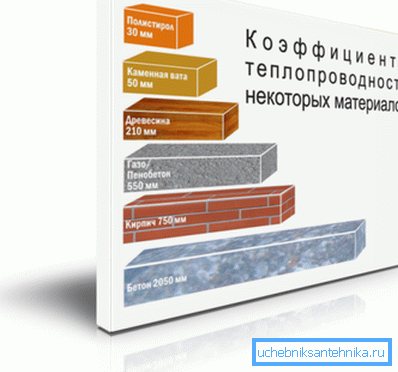
Determination of heat loss
In order to calculate the need for thermal energy at home, you need to know the amount of heat loss occurring through the walls, floor and ceiling. To do this, it is possible to use the table in which the thermal conductivity of different materials is indicated.
| Name | Thickness, cm | Coefficient of thermal conductivity |
| Styrofoam | 0,11 | 0,037 |
| Glass wool | 0,12 | 0,041 |
| Mineral fiber | 0,13 | 0,044 |
| Planed timber | 0,44 | 0,15 |
| Aerated concrete | 0,54 | 0,183 |
| Foam concrete | 0,62 | 0,21 |
| Brick | 0,79 | 0,27 |
But, in order to correctly find out the heat losses and calculate the boiler power, there will be not enough to know the thermal conductivity of the materials.
It is also necessary to include certain amendments into the calculation formula:
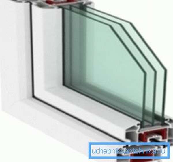
- Construction and material of the glass units used:
- simple wooden windows - 1.27,
- metal-plastic window blocks with double glazing 1,
- polymer window frames with triple glazing 0.85.

- Glazing area of the house. Everything is simple here. The higher the ratio of the area of windows to the area of the floor, the greater the heat loss of the building. For calculations, it is possible to take the following coefficients:
| Window / wall ratio | Correction factor |
| 0,1 | 0,8 |
| 0,15 | 0,9 |
| 0,2 | 1 |
| 0,25 | 1,1 |
| 0,3 | 1,2 |
| 0,35 | 1,3 |
| 0,4 | 1,4 |
| 0,5 | 1,5 |

- Average daily outside air temperature. This correction must also be taken into account, since at too low values the coefficient of heat loss through the walls and windows increases. The following values are accepted for calculations:
| Temperature | Correction factor |
| up to - 10 оС | 0,7 |
| - 10 оС | 0,8 |
| - 15 оС | 0,9 |
| - 20 оС | 1 |
| - 25 оС | 1,1 |
| - 30 оС | 1,2 |
| - 35 оС | 1,3 |
- Number of exterior walls. If the room is located in a house, then only one wall comes into contact with the outside air - the one where the window is located. But, corner rooms or rooms in small buildings can have two, three, and four outer walls. In this case, the following correction factors must be taken into account:
- one room - 1,
- two rooms - 1.2,
- three rooms - 1.22,
- four rooms - 1.33
- Number of floors. As in the past, the number of floors and (or) the presence of an attic affects heat loss. In this case, it is necessary to take the following values for the corrections:
- the presence of several floors - 0.82,
- insulated roof or attic floor - 0.91,
- non-insulated ceiling - 1.

- Distance between walls and ceiling. As we know, the huge height of the ceilings increases the amount of the room, therefore, more heat must be spent on heating it. The coefficients in this case are used as follows:
| Height | Correction factor |
| 2.5 meters | 1 |
| 3 meters | 1,05 |
| 3.5 meters | 1,1 |
| 4 meters | 1,15 |
| 4.5 meters | 1,2 |
In order to calculate the heating, you need to multiply all the above coefficients and find out Tdomapo using the following formula:
Tdoma = Pud * Knespecialized * S, where:
- Pud - specific heat loss (in most cases, 100 W / m2)
- Non-specialized - non-specialized correction, obtained by multiplying all the above coefficients,
- S - housing construction area.
Calculation of water consumption for heating - Heating system
»Heating calculations
The heating design includes a boiler, a connection system, air supply, thermostats, manifolds, fasteners, an expansion tank, batteries, pressure-increasing pumps, pipes.
Any factor is definitely important. Therefore, the choice of installation parts must be done correctly. On the open tab, we will try to help you choose the necessary installation parts for your apartment.
The heating installation of the mansion includes important devices.
Page 1
The estimated flow rate of network water, kg / h, to determine the diameters of pipes in water heating networks with high-quality regulation of heat supply should be determined separately for heating, ventilation and hot water supply according to the formulas:
for heating
(40)
maximum
(41)
in closed heating systems
average hourly, with a parallel circuit for connecting water heaters
(42)
maximum, with a parallel circuit for connecting water heaters
(43)
average hourly, with two-stage connection schemes for water heaters
(44)
maximum, with two-stage connection diagrams of water heaters
(45)
Important
In formulas (38 - 45), the calculated heat fluxes are given in W, the heat capacity c is taken equal. These formulas are calculated in stages for temperatures.
The total estimated consumption of network water, kg / h, in two-pipe heating networks in open and closed heat supply systems with high-quality regulation of heat supply should be determined by the formula:
(46)
Coefficient k3, taking into account the share of the average hourly water consumption for hot water supply when regulating the heating load, should be taken according to table No. 2.
Table 2. Coefficient values
r-Radius of a circle equal to half the diameter, m
Q-flow rate of water m 3 / s
D-Internal pipe diameter, m
V-speed of the coolant flow, m / s
Resistance to the movement of the coolant.
Any coolant moving inside the pipe strives to stop its movement. The force that is applied to stop the movement of the coolant is the resistance force.
This resistance is called pressure loss. That is, the moving heat carrier through a pipe of a certain length loses pressure.
The head is measured in meters or in pressures (Pa). For convenience, it is necessary to use meters in the calculations.
Sorry, but I'm used to specifying head loss in meters. 10 meters of water column create 0.1 MPa.
In order to better understand the meaning of this material, I recommend following the solution of the problem.
Objective 1.
In a pipe with an inner diameter of 12 mm, water flows at a speed of 1 m / s. Find the expense.
Decision:
You must use the above formulas:
Calculating the volume of water in the heating system with an online calculator
Each heating system has a number of significant characteristics - nominal thermal power, fuel consumption and the volume of the coolant. Calculation of the volume of water in the heating system requires an integrated and scrupulous approach. So, you can find out which boiler, what power to choose, determine the volume of the expansion tank and the required amount of liquid to fill the system.
A significant part of the liquid is located in pipelines, which occupy the largest part in the heat supply scheme.
Therefore, to calculate the volume of water, you need to know the characteristics of the pipes, and the most important of them is the diameter, which determines the capacity of the liquid in the line.
If the calculations are made incorrectly, then the system will not work efficiently, the room will not warm up at the proper level. An online calculator will help to make the correct calculation of volumes for the heating system.
Heating system liquid volume calculator
Pipes of various diameters can be used in the heating system, especially in collector circuits. Therefore, the volume of liquid is calculated using the following formula:
The volume of water in the heating system can also be calculated as the sum of its components:
Taken together, these data allow you to calculate most of the volume of the heating system. However, in addition to pipes, there are other components in the heating system. To calculate the volume of the heating system, including all the important components of the heating supply, use our online calculator of the volume of the heating system.
Advice
Calculating with a calculator is very easy. It is necessary to enter in the table some parameters concerning the type of radiators, diameter and length of pipes, volume of water in the collector, etc. Then you need to click on the "Calculate" button and the program will give you the exact volume of your heating system.
You can check the calculator using the above formulas.
An example of calculating the volume of water in the heating system:
The values of the volumes of various components
Radiator water volume:
- aluminum radiator - 1 section - 0.450 liters
- bimetallic radiator - 1 section - 0.250 liters
- new cast iron battery 1 section - 1,000 liters
- old cast iron battery 1 section - 1,700 liters.
The volume of water in 1 running meter of the pipe:
- ø15 (G ½ ") - 0.177 liters
- ø20 (G ¾ ") - 0.310 liters
- ø25 (G 1.0 ″) - 0.490 liters
- ø32 (G 1¼ ") - 0.800 liters
- ø15 (G 1½ ") - 1.250 liters
- ø15 (G 2.0 ″) - 1.960 liters.
To calculate the entire volume of liquid in the heating system, you also need to add the volume of the coolant in the boiler. These data are indicated in the accompanying passport of the device, or take approximate parameters:
- floor boiler - 40 liters of water;
- wall-mounted boiler - 3 liters of water.
The choice of the boiler directly depends on the volume of liquid in the heating system of the room.
The main types of coolants
There are four main types of fluid used to fill heating systems:
In conclusion, it should be said that if the heating system is being modernized, pipes or batteries are installed, then it is necessary to recalculate its total volume, according to the new characteristics of all elements of the system.
Heat carrier in the heating system: calculation of volume, flow rate, injection and more
In order to have an idea of the correct heating of an individual house, you should delve into the basic concepts. Consider the processes of circulation of the coolant in heating systems. You will learn how to properly organize the circulation of the coolant in the system. It is recommended to watch the explanatory video below for a deeper and more thoughtful presentation of the subject of study.
Calculation of the coolant in the heating system ↑
The volume of the coolant in heating systems requires an accurate calculation.
The calculation of the required volume of coolant in the heating system is most often done at the time of replacement or reconstruction of the entire system. The simplest method would be to banal use of the appropriate calculation tables. They are easy to find in thematic reference books. According to the basic information, it contains:
- in the section of the aluminum radiator (battery) 0.45 l of the coolant;
- in the section of the cast-iron radiator 1 / 1.75 liters;
- running meter of 15 mm / 32 mm pipe 0.177 / 0.8 liters.
Calculations are also required when installing the so-called make-up pumps and an expansion tank. In this case, in order to determine the total volume of the entire system, it is necessary to add up the total volume of heating devices (batteries, radiators), as well as the boiler and pipelines. The calculation formula is as follows:
V = (VS x E) / d, where d is an indicator of the efficiency of the installed expansion tank; E represents the coefficient of expansion of the liquid (expressed as a percentage), VS is equal to the volume of the system, which includes all the elements: heat exchangers, boiler, pipes, also radiators; V is the volume of the expansion tank.
Regarding the coefficient of expansion of the liquid. This indicator can be in two values, depending on the type of system.If the heat carrier is water, for the calculation its value is 4%. In the case of ethylene glycol, for example, the expansion coefficient is taken as 4.4%.
There is another, rather common, albeit less accurate, option for assessing the volume of the coolant in the system. This is the way in which power indicators are used - for an approximate calculation, you only need to know the power of the heating system. It is assumed that 1 kW = 15 liters of liquid.
An in-depth assessment of the volume of heating devices, including the boiler and pipelines, is not required. Let's consider this with a specific example. For example, the heating capacity of a particular house was 75 kW.
In this case, the total volume of the system is deduced by the formula: VS = 75 x 15 and will be equal to 1125 liters.
It should also be borne in mind that the use of various additional elements of the heating system (be it pipes or radiators) somehow reduces the total volume of the system. Comprehensive information on this issue is found in the corresponding technical documentation of the manufacturer of certain elements.
Useful video: circulation of coolant in heating systems ↑
Heating agent injection into the heating system ↑
Having decided on the indicators of the volume of the system, the main thing should be understood: how the coolant is pumped into the closed-type heating system.
There are two options:
In the process of pumping, you should follow the readings of the pressure gauge, not forgetting that the air vents on the heating radiators (batteries) must be open without fail.
Heating agent flow rate in the heating system ↑
The flow rate in the heat carrier system means the mass quantity of the heat carrier (kg / s) intended to supply the required amount of heat to the heated room.
Calculation of the heat carrier in the heating system is determined as the quotient of dividing the calculated heat demand (W) of the room (s) by the heat transfer of 1 kg of heat carrier for heating (J / kg).
The flow rate of the heating medium in the system during the heating season in vertical central heating systems changes, since they are regulated (this is especially true for the gravitational circulation of the heating medium. In practice, in calculations, the flow rate of the heating medium is usually measured in kg / h.
Other methods of calculating the amount of heat
It is possible to calculate the amount of heat entering the heating system in other ways.
The calculation formula for heating in this case may differ slightly from the above and have two options:
- Q = ((V1 * (T1 - T2)) + (V1 - V2) * (T2 - T)) / 1000.
- Q = ((V2 * (T1 - T2)) + (V1 - V2) * (T1 - T)) / 1000.
All variable values in these formulas are the same as before.
Based on this, it is safe to say that the calculation of kilowatts of heating can be done on your own. However, do not forget about consulting with special organizations responsible for supplying heat to dwellings, since their principles and settlement system can be completely different and consist of a completely different set of measures.
Having decided to design a so-called "warm floor" system in a private house, you need to be prepared for the fact that the procedure for calculating the amount of heat will be much more complicated, since in this case you should take into account not only the features of the heating circuit, but also provide for the parameters of the electrical network, from which and the floor will be heated. At the same time, the organizations responsible for control over such installation work will be completely different.
Many owners often face the problem of converting the required number of kilocalories to kilowatts, which is caused by the use of measurement units in many auxiliary aids in the international system called "C". Here you need to remember that the coefficient converting kilocalories to kilowatts will be 850, that is, in simpler terms, 1 kW is 850 kcal. This calculation procedure is much easier, since it will not be difficult to calculate the required amount of giga calories - the prefix "giga" means "million", therefore, 1 giga calorie is 1 million calories.
In order to avoid errors in calculations, it is important to remember that absolutely all modern heat meters have some error, often within acceptable limits. The calculation of such an error can also be performed independently using the following formula: R = (V1 - V2) / (V1 + V2) * 100, where R is the error of the general house heating meter
V1 and V2 are the parameters of the water flow in the system already mentioned above, and 100 is the coefficient responsible for converting the obtained value into percent. In accordance with operational standards, the maximum permissible error can be 2%, but usually this figure in modern devices does not exceed 1%.