The principle of operation and features of the Planar heater
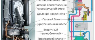
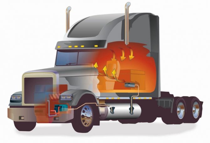
The Planar heater runs on its own fuel according to the convection principle
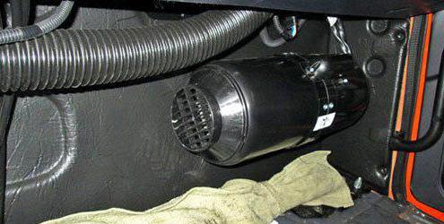
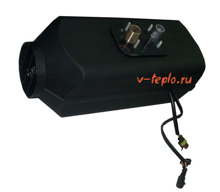
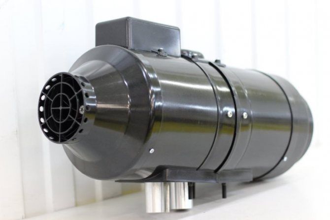
The Planar heater is a product of Russian and Teplostar. The principle of operation is simple: the device draws in air, warms up and returns it back to the passenger compartment. The device uses its own diesel fuel for heating - its operation does not depend on the engine of the car. For the device to function, it must be connected to a 12 or 24 V DC network.
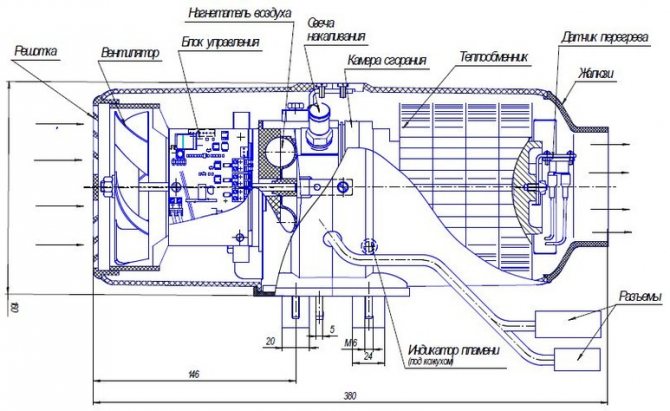
The design is simple:
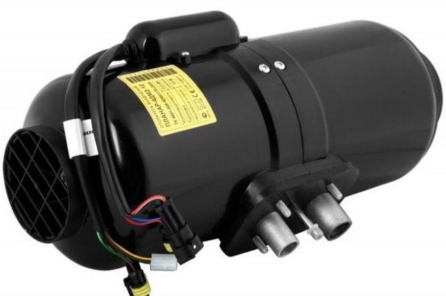
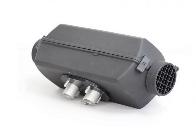
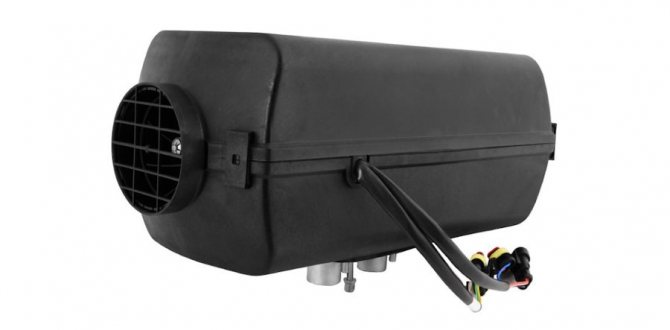
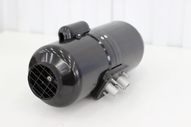
- All elements are located in a cylindrical or box-shaped body.
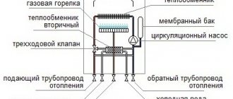
- Diesel fuel is taken through a tube from the tank of a diesel vehicle or a special heating tank. The pump supplies fuel.
- The diesel fuel flows through the pipe to the nozzle of the combustion chamber. The glow plug is located here. Diesel fuel burns in the chamber.
- Diesel fuel requires air to burn. The supply is carried out through a flexible hose connected to the inlet pipe. Air is forced by means of a fan.
- The gas obtained during combustion leaves through the chambers and gives off heat through the heat exchanger to the main air masses. Smoke is discharged through the air vent hose outside the passenger compartment.
- An electrically driven fan circulates air. First, it cools the electric motor and heats up from it. Then it passes through the heat exchanger and its temperature increases even more. Warm air is supplied to the passenger compartment.
- The commutation of the blocks is performed by a loop with decks-connectors. Their shape is such that it excludes erroneous connection. Adjust the functions of the device using a remote control or other modification.
- The safety of the heater is ensured by a number of sensors and monitoring devices. The indicator monitors the flame in the combustion chamber, the temperature sensor measures the temperature of the air leaving the device, and so on.
The operation of the device can be controlled by the remote control or by means of the regulator directly on the body. The heater functions automatically: when the temperature in the passenger compartment reaches the set value, the Planar turns off, when it falls, it turns on.


Features of work in various situations
Of course, the Planar heating device is very useful and irreplaceable in cold winters. However, many motorists do not risk installing it, as they are afraid of incorrect operation in emergency situations.
The engineers took into account all possible features of the device's operation in various conditions. Let's take a look at some of them:
- The operation of the heater is constantly monitored by automatics. If it is defective, the warning LED (orange or red) lights up
- The device will not allow the heat exchanger to overheat - in such a situation, it will turn off
- There may be cases when combustion stops for spontaneous reasons - in such situations, the installation is automatically turned off.
- As a result of an unsuccessful start of the heating equipment, the automation will make several repeated starts. If each of them fails, a fault warning will be issued.
- Onboard voltage 12 V (device 4DM-12) - from 10.5 V to 16 V
- Onboard voltage 24 V (device 4DM-24) - from 20.5 V to 30 V
Constant power surges can be very unsafe. The control unit will ensure the operability of the device only in situations where it does not go beyond the normal range:
Overheating is often caused by improper installation of equipment. It occurs when the inlet and outlet of the heater have been blocked.
Advantages and disadvantages
The device can work autonomously when the engine of the machine is turned off
The Planar heater helps out many drivers.Truckers, bus drivers, travelers have to spend a lot of time in the cab of the car. In the cold season, the heating of the passenger compartment due to the operation of the engine is insufficient. Planar solves this problem.
Advantages of the device:
- In an hour, the heater, depending on its power, heats from 34 to 120 cubic meters. m. of air.
- The planar is economical - with such a high efficiency it consumes no more than 29-42 watts. The same volume of heated air requires 0.24 to 0.37 liters of diesel fuel per hour.
- The planar is effective at very low temperatures overboard - below -20 C.
- The installation works without time limits. It turns off automatically when the specified temperature is reached and turns on when it drops. You can turn off the device manually.
- The device is safe. In the event of a rollover, low flame, extinction of the flame, interruptions in the supply of air or fuel, the Planar switches off.
- The noise level is low.
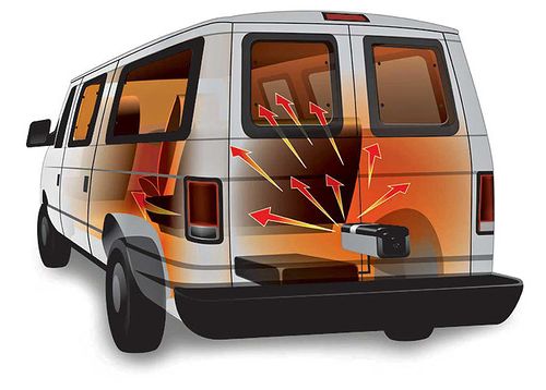
- If you connect the air outlet pipes, warm air can be directed not only into the cabin, but also into the passenger compartment of the bus or into the cargo compartment if the cargo being transported needs a certain temperature regime.
- The device works autonomously from the car engine. This is a convenient option for spending the night in a car, as the Planar can heat the cabin all night.
There are no disadvantages. Autonomous car heater Planar fully meets its purpose.
The heater is used not only in cars, but also for heating change houses, vans, booths, tents.
The principle of operation and features of the device
One of the advantages of a planar heater is the ability to adjust the heating power. For this, the device has a special knob on the regulator, which can be easily turned and set to the desired position.
Having set the desired power value, there is no need to interfere with the further operation of the device. It will be monitored automatically:
- When the temperature drops to a critical minimum mark - Planar turns on
- A constant increase in heat inside the passenger compartment will gradually reduce power, reducing the supply of warm air
Package contents and characteristics
The complete set of the heater includes all units and parts of the device. The number and type of additional elements depends on the model. All fasteners are mandatory - washers, bolts, clamps, corners with gaskets, plugs, screens, and also all connecting elements - power harness, fuel pump, exhaust pipe. The planar is equipped with its own fuel tank and control panel.
There are 4 types of device. The main characteristics are shown in the table.
| Model | 2D-12-S (24 S) | 4DM2-12-S (24 S) | 44D-12-GP-S (24 S) | 8M-12-S (24 S) |
| Rated voltage, V | 12 (24) | 12 (24) | 12 (24) | 12 (24) |
| Thermal power, kW (max and min) | 0,8–2,0 | 1,0–3,0 | 1,0–4,0 | 2,0–6,0 |
| Fuel consumption, l / h (max and min) | 0,1–0,24 | 0,12–0,37 | 0,12–0,51 | 0,42– 0,76 |
| Power consumption, W (maxi and min) | 10–29 | 9–38 | 10–58 | 8–85 |
| The volume of heated air, cubic meters m / hour (max min) | 34–75 | 70–120 | 70–120 | 70–175 |
| Start and stop mode | Manual / Remote | Manual | Manual / Remote | Manual |
| Weight, kg | 10 | 10 | 10 | 12 |
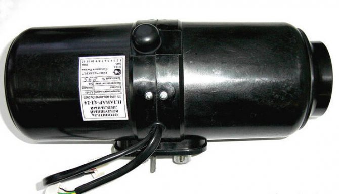
Air heater Planar 4DM2 24 differs from 12 only in requirements for current strength - 24 V, not 12 V.
All Planar models run on diesel fuel. If the supply is carried out from its own tank, the diesel fuel is diluted with kerosene in certain proportions. The ratio depends on the type of diesel fuel and temperature.
Main characteristics (for example, model 44D):
| Characteristic | Small mode | Intensive mode |
| Performance (heating) | 1 kilowatt | 4 kilowatts |
| Fuel consumption | 0.12 liters | 0.514 liters |
| Heated air (cubic meters) | 70 | 120 |
| Operating power | 10 | 62 |
| Working voltage | 12 volts | 24 volts |
| Kit weight | 8 kilograms | 8 kilograms |
Note!
The equipment runs on diesel fuel, GOST305. Stopping and starting is done manually.
Monitoring and control system
The control unit can be used to regulate the amount of heat
The Planar heater operates in several modes. Operational safety, regulation and diagnostics of systems are provided by sensors and a control unit.
Control block
The module is located in the housing and connected to the executive blocks with commutation loops. Its functions are as follows:
- turning on and off the device;
- control and management of the fuel combustion process;
- initial diagnostics in case of breakdowns during start-up;
- automatic ventilation after stopping the Planar;
- emergency shutdown in the event of a breakdown of any unit, flame attenuation, power surges, heat exchanger overheating and other situations.
The control unit works together with the remote control.
Modes of operation
The device simultaneously performs the function of interior ventilation
The autonomous engine air heater operates in 3 modes. However, the use often depends on the configuration of the model:
- By power - heats up the interior as quickly as possible. The heater, set to a certain power level - from 1 to 8, works continuously until the device is turned off manually.
- By temperature - the heater heats up the air to the set temperature. Then the heater is switched off and automatically switched on again as soon as the air cools down to the specified minimum. In automatic mode, the device operates until it is manually turned off.
- Ventilation - provides air exchange. Combines with temperature or power control. At the same time, the temperature is maintained with high accuracy, does not fluctuate within the specified range.
The temperature and power are set before starting. Parameters cannot be adjusted during operation.
Control panels
The remote control is installed on the dashboard or hung on a container in any place convenient for the driver. The device is connected to the device by a loop. The console is convenient in that it regulates the work of the Planar and serves as a diagnostic tool.
Heaters are equipped with different types of remote controls:
- PU-10M - allows the Planar to operate in power and temperature modes, ventilation is not provided. Equipped with LED indicator.
- PU-5 - allows the Planar to work in all modes. The potentiometer handwheel is equipped with a conventional graduation, so that the temperature can be set more accurately. The indicator indicates work and malfunctions.
- PU-22 - functional buttons allow you to select a mode, a temperature sensor, the readings of which will be considered control, change the power and temperature indicators. Information about the work of the Planar and breakdowns is reflected on the LED screen.
By the number, color and behavior of the LEDs, you can determine the cause of the malfunction and quickly eliminate it.
Heater PLANAR - 4D - Auto parts and tricks

Skip to content
Main menu:
- Let's start ...
DIAGRAMS in one click DAF XF-105 2006-2013 - XF 2013-2017
- 95XF
- MAGNUM 2000-2006
- Tricks
- WORKSHOP Information READ DIAGRAMS
- Practice
- Codes 5556, 5038
- Pressurization
- EDC EDC
- EBS
- OBD system
- TGS / TGX Wiring diagrams
- Using
- Wiring diagrams
- EDC MS 5 Trouble Shooting
- Options description
- Search for failures
- Fault codes
- Fault codes
- Fault codes
- Fault codes
- Fault codes
- Fault codes
- Fault codes
- Fault codes
- TGA AS-Tronic
- Fault codes
- Fault codes
- Fault codes
- Description
- Fault codes
- Fault codes
- Fault codes
- Fault codes
- Airtronic Fault Codes
- Description
- Fault codes
- Fault codes
- Fault codes
- Fault codes
- Fault codes
- Description
- Electrical equipment
- MAN EURO 6
- Tricks
- MX-11 / MX-13, EN2 / 14 MX motors
- PACCAR
- "MIL" for ECS-DC4 and EAS
- Decoding
- ECAS-2
- ABS / ASR-D
- EST42
- EAS
- Abbreviations
- troubleshooting
- EST 52
- ACH-EW
- EBS
- Cab suspension
- CAN Topology
- ZF EST42
- EBS 2
- Description
- Pneumatics
- BBM
- Wiring diagrams
- Wiring diagrams
- Diagnostics
- Components LF45 IV, LF55 IV
- ACTROS 950-954 Reg. engine
- Tricks
- MR euro 2-3
- MR "Code"
- Rear module
- Automatic gearbox GS II
- Automatic gearbox GS II
- TCM TCM
- MCM
- ATEGO codes 950 - 954
- Wiring diagrams MR OM904
- ABS wiring diagrams
- Wiring diagrams MR MR
- ABS / ASR
- MR Wiring diagrams
- Wiring diagrams ADM
- Wiring diagrams HYD
- Wiring diagrams MR
- Wiring diagrams MR
- SPRINTER 909 CR4_T1N-OM646
- CDID3S2- OM651
- EURO TRAKKER Wiring diagrams
- TECTOR
- Wiring diagrams
- Wiring diagrams
- Checkpoint Eurotronic
- Repair zone Workshop HPI with EDC S6 Fuel pressure
- In winter
- Introduction
- Engine
- Description
- Diagnostics
- Description
- EBS System Design
- ABS BOSCH
- Diagnostics
- PDE (EDC) MS6 Diagnostics
- Description MS5
- Components
- AGR
- Rem. Smoke zone
- VIN code
- Balance checks. cylinder
- FM4 description
- FH4 D13 A400
- EBS Description
- Description
- FM (4) Wiring diagram
- Wiring diagrams
- Designations
- Wiring diagrams
- Wiring diagrams
- FH (4) Wiring diagrams
- ECM
- MID 128 D9, D12, D16
- MID codes 144
- VN / VHD / VAN
- euro 6
- Service
- TRAINING ... Posting
- LCM
- Designations
- Wiring diagrams
- Wiring diagrams
- EURO 4 Wiring diagrams
- Wiring diagrams
- Wiring diagrams
- Wiring diagrams
- Service. instructions
- AUMAN Electro system
- CARGO Wiring diagram
- Fault codes S05C / D_S05C-TB
- J and S series
- Wiring diagrams
- Wiring diagrams
- Components
- SX3255DR
- Wiring diagram
- Canter EURO 3 Wiring diagram
- Common Rail Engine
- FLC Cummins
- T800
- MB EURO 3/4 scheme
- Wiring diagrams Cummis CM2150
- BOSCH MS 6.1
- knee / camshaft
- CUMMINS
- AS-Tronic
- Description
- 5490 Wiring diagram
- ABS
- ABS
- 6370 ABS 6 Device
- Rem. VOLVO zone Read diagrams
- Wiring diagrams 203
- Scania Touring Electrical
- Automatic gearbox ZF
- Pneumatics
- Suspension Suspension ELC
- B12B_B12M
- BH120F
- NL243 / 283
- Wiring diagrams
- 5292_22
- Futura
- ECU CM2150E
- Engine
- SB 220 GS / LT
- XMQ6120C
- E200 MMC
- A092 / A0921
- ETS and MTS
- Komatsu Tech. documentation
- PC200 (220) 6 Excel
- CAT Dictionary
- EX300 - 5
- Collection of diagrams
- LTM 1100 Fault codes
- LR1600
- Fault codes
- EK-18 Perkins
- Mega collection
- JS145W
- Fault codes Telescope CODE
- Mini loader
- Fault codes
- Fault codes
- Front. series 3
- Tractor T6 Trouble Codes
- Tractor T9
- Front loader
- Front. series 3
- Fault codes
- Wiring diagrams
- DL wiring diagrams
- DL
- BW 213/214 Wiring diagrams
- Wiring diagrams CVT 6140 - 61195
- We read the diagrams
- 350D and 400D-II
- 210K EP
- 540H and 548H
- 9120 — 9620
- 335C
- 318E and 320E
- 210LE
- 9560, 9660 Wiring diagrams
- XCG 210LC-8B
- Wiring diagrams
- Jaguar 695
- Service info.
- A350 charts
- Schemes
- SUPER 2500
- BHL
- SAME
- H12T-H20T
- Collection of diagrams
- Service manual
- Service. collection
- LOGLIFT 59
- NH / Case / Steyr
- WORKSHOP Simulator Knorr
- ECAS
- Systems
- EBS D system
- Components
- EBS E system
- Thermo King Wiring Diagrams
- Wiring diagrams
- System
- TEBS TEBS 4
- VOLVO VOLVO PTT 2.7 ...
- Autocom Mercedes Actros Diagnostics
- Diagnostics-video
- ABS sensors
- DAVIE DAVIE and fuel
- ABS 6 Diagnostics
- Rem. zone TEBS E
- Components
- Description
- Teplostar 14TS-10
- Fault codes
- Calculation of heaters
- AIRTRONIC
- 4D-24
- AT 2000
- Description
- Webasto BBW / DBW46
- Thermo 300
- DAF
- CUMMINS Cummins ISB / ISBe Fault Codes
- Fault codes
- Description
- Fault codes
- Diagnostics
- EMR3
- Tier 3 Fault Codes
- DDEC components
- 4.5L and 6.8L
- MX-13 Fuel
- TELMA Wiring diagrams
- 3000_4000 series
- ESU - 1A Diagnostics
- ECU description
- CM2150
- CP malfunctions
- ABS-T Diagnostics
- Screen components
- VOCOM I, II
- Shop spare parts (used) MAN
See also:
Diagnostics
Autonomous heater PLANAR - 4D
Heater control unit (CU)
The control unit provides control of the heater together with the control panel.
BU performs the following functions:
a) initial diagnostics (serviceability check) of the heater units at startup;
b) diagnostics of heater units during the entire operation;
c) turning on and off the heater by command from the control panel;
d) control of the combustion process;
e) automatic shutdown of the heater:
- in case of loss of performance of one of the monitored nodes;
- when the parameters go beyond the permissible limits (heat exchanger temperature, supply voltage and flame failure in the combustion chamber).
Purpose of the control panel
The control panel (panel) is intended for use as part of the heater as a device providing manual control of the heater.
The remote control is intended for:
- starting (heating or ventilation mode) and stopping the heater in manual mode;
- changes in the manual mode of the heater (heating temperature or ventilation intensity);
- indication of the heater status (the LED lights up red - heating mode, green - ventilation mode, blinking red - malfunction (alarm), off - the heater does not work.
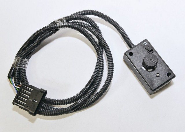
The device of the remote control and work with it
On the front panel of the control panel there are: the switch knob (item 1) and the LED (item 2).
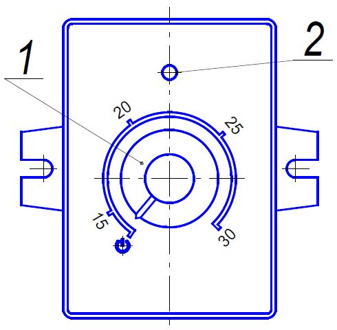
The switch handle is designed to execute the following commands:
- when the switch knob is set to the extreme left position (after a click), the heater is turned off;
- when turned clockwise after clicking, the heater will turn on to heating or ventilation mode. To change the operating mode, it is necessary to make a double switch on with an interval of at least 2 seconds between clicks;
- when the knob is set (in heating mode) to any position, the heater will operate with a heating output ranging from 1 to 3 kW, depending on the position of the switch knob, and in ventilation mode with a certain fan speed.
LED pos. 2 indicates the heater status:
- lights up green - ventilation mode;
- lights up red - heating mode;
- blinking red - in case of malfunction (emergency). The number of flashes after a pause corresponds to the fault code;
- does not light up - when the heater is not working.
Malfunctions, their causes and methods of elimination
Explanation of the number of flashes in case of a heater malfunction
LED flashes
Fault description
Trouble-shooting
1
Overheating of the heat exchanger
Check the inlet and outlet pipes of the heater for free inlet and outlet of heated air.
2
Start attempts have been exhausted
If the permissible number of start attempts has been used, check the amount and supply of fuel. Check the combustion air supply and flue gas line.
3
Flame interruption
Check the amount and supply of fuel. Check the combustion air supply and flue gas line. If the heater starts, check the flame indicator and replace if necessary.
4
Glow plug malfunction
Air blower motor malfunction
Check the glow plug, replace if necessary.
Check the wiring of the blower motor, replace the blower if necessary
5
Flame indicator malfunction
Check the flame indicator circuit for an open, with the resistance between the terminals not exceeding 1 ohm.
If the indicator is defective, then it must be replaced.
7
Fuel pump malfunction
Check the fuel pump wiring for a short circuit, replace if necessary.
8
There is no communication between the control panel and the control unit
Check connecting wires, connectors.
9
Shutdown, overvoltage
Shutdown, undervoltage
Check the battery, regulator and power supply wiring. The voltage between 1 and 2 pins of the XP13 connector must be no higher than 30 V (15 V).
Check the battery, regulator and power supply wiring. The voltage between 1 and 2 pins of the XP13 connector must be at least 20 V (10.8 V).
10
Time for ventilation exceeded
The heater is not cooled sufficiently during the purge. Check combustion air system and flue gas line. Check flame indicator and replace if necessary.
Let's start ... |
Installation requirements
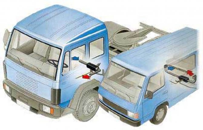
The device can be placed anywhere in the car, the control panel is next to the driver
Installation of the Planar is carried out strictly according to the instructions:
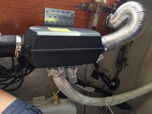
- The heater is fixed to both the wall and the floor. The position is strictly horizontal, tilt is prohibited.
- The distance from the walls or partitions to the inlet is at least 5 cm.
- The distance from the walls of the cabin from the outlet is at least 15 cm.
- The heater is installed in a place where it can be repaired and dismantled.
- The body must not come into contact with the walls or the floor of the cab.
- The fuel tank must not be installed in the passenger compartment, trunk or engine compartment. It is fixed in such a way that when the diesel fuel spills, it does not end up on the wiring.
- Combustion air is taken from outside, not from the passenger compartment or cargo hold. The suction port is positioned against the airflow while driving.
Place the inlet so that the Planar does not suck in exhaust gases during operation.
Installation of an autonomous heater Planar
If you decide to do it yourself, you must take into account the following rules:
- The fuel line must not be laid in the passenger compartment.
- Do not refuel when the heater is on.
- Do not connect the power supply until the entire electrical system of the heater is fully assembled.
- Connection is only permissible for a battery.
- All connectors must be protected from moisture.
IMPORTANT! It is preferable to entrust the installation of the heater to specialists.
The Bayar company provides services for the installation of heaters of this brand, and also carries out their repair and maintenance.
Possible error codes and malfunctions

Planar heater error codes
The Planar display system signals errors. A number of breakdowns can be eliminated by yourself:
- 1 on the screen or blinking of the indicator - overheating of the heat exchanger. It is necessary to check the passage of air through the heater.
- 2 or 12 short blinks after a pause - overheating of the device itself. Check the pipes and the air supply to the combustion chamber.
- 12 or 15 or 9 fast flashes indicate power surges. The device turns off.
- 12 or 2 blinks - start is impossible due to lack of fuel, air, disturbance in the exhaust gas outlet.
- 20 or 30 and 8 blinks - communication is lost between the module and the control panel. Check the loops.
- 29 or 3 blinks of the LED - flameout in the burner. You need to check the fuel supply.
- 35 or 13 blinks is an 8DM only bug. Flame blowout due to low voltage.
- 78 - marked only on the screen. This is a warning that flame blowout occurs too often.
Malfunctions indicated by the following codes cannot be remedied by yourself. Dismantling of the device and specialist intervention is required:
- 4 or 6 or 6 blinks - the temperature sensor is out of order.
- 5 or 5 blinks - the flame indicator is broken.
- 9 or 4 blinks - the problem is the glow plug.
- 10, 27, 28 or 11 flashes - the electric drive is damaged;
- 11 on the screen or 18 blinks - the temperature sensor on the supply pipe is broken.
- Problems on the inlet pipe are coded with 23 or 15 blinks.
- 17 or 7 flashes - fuel pump failure.
- The appearance of the digit 33 or 16 flashes after a pause indicates that the device is blocked, because overheating was registered three times in a row. Unlocking is carried out only at a service center.
- 36 or 20 blinks - the flame temperature sensor detects too high a temperature.
It is impossible to ignore the readings of the device. If errors of the same type are repeated, the device is blocked or fails.

Autonomous "Planar": reviews
Among users, especially those who spend a lot of time on the road, the device in question is popular. Car owners note the simplicity of its installation and maintenance, reliability and low cost in comparison with foreign counterparts.
Especially consumers highlight the following advantages of the device:
- The possibility of conducting air duct tubes into the cargo area, which allows heating not only the cab, but the entire vehicle.
- High efficiency of work even in frosts down to -20 degrees.
- Economical fuel consumption and battery life.
- Acceptable power setting.
- Unlimited life of the device.
Operating instructions for the heater Planar
You can install and run Planar yourself, but if you have no experience with heating systems, you need to invite a specialist.
When switched on, the Planar conducts testing, and if all elements are in good working order, it starts firing up. First, the chamber is purged, then diesel fuel and air are supplied. The burner works until the sensor fixes the set value. After that, the device turns off if it does not work in power mode.
After manual shutdown, the Planar is automatically ventilated.
Safety engineering

When refueling, the Planar must be turned off.
A cockpit or car salon is a very small space. Safety precautions must be strictly observed:
- there must be a fire extinguisher in the car, in a change house or garage - at least a bucket of sand;
- it is prohibited to lay the fuel line inside the passenger compartment or cabin;
- during refueling, the device is turned off;
- during repair and welding work, the heater is disconnected from the battery;
- before the end of the purge, it is forbidden to disconnect the device from the mains;
- after stopping the device, restarting is performed not earlier than after 5-10 seconds.
If the safety regulations are not followed, the manufacturer has the right to refuse warranty service.
Features of the
To keep the formed flame within the normal range, its intensity is controlled by a special sensor. If the maximum temperature is exceeded, the control unit deactivates combustion.
Despite the high level of automation, the installation of the "Planar" autonomous system involves turning off the device in manual mode. After that, the combustion compartment begins to ventilate, and the fuel supply is completely stopped.
The flow of fuel into the heater chamber, as a rule, is carried out directly from the vehicle's fuel tank. Another way of supplying an autonomous system is to have its own container, which stores the supply of fuel necessary for operation.
The unit is powered directly from the vehicle battery.