If you pay enough attention to the comfort in the house, then you will probably agree that air quality should come first. Fresh air is good for your health and thinking. It's not a shame to invite guests to a room that smells good. Airing every room ten times a day is not an easy task, is it?
Much depends on the choice of the fan and, first of all, its pressure. But before you can determine the fan pressure, you need to familiarize yourself with some of the physical parameters. Read about them in our article.
Thanks to our material, you will learn the formulas, learn the types of pressure in the ventilation system. We have provided you with information about the total head of the fan and two ways in which it can be measured. As a result, you will be able to measure all parameters yourself.
Ventilation system pressure
For ventilation to be effective, the fan pressure must be correctly selected. There are two options for self-measuring the pressure. The first method is direct, in which the pressure is measured in different places. The second option is to calculate 2 types of pressure out of 3 and get an unknown value from them.
Pressure (also - head) is static, dynamic (high-speed) and full. According to the latter indicator, there are three categories of fans.
The first includes devices with a head <1 kPa, the second - 1-3 kPa and more, the third - more than 3-12 kPa and above. In residential buildings, devices of the first and second categories are used.
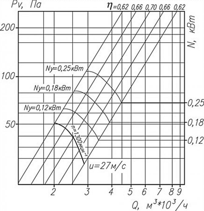
Aerodynamic characteristics of axial fans on the graph: Pv - total pressure, N - power, Q - air flow, ƞ - efficiency, u - speed, n - rotation frequency
In the technical documentation for the fan, aerodynamic parameters are usually indicated, including the total and static pressure at a certain capacity. In practice, the "factory" and real parameters often do not coincide, and this is due to the design features of ventilation systems.
There are international and national standards aimed at improving the accuracy of measurements in the laboratory.
In Russia, methods A and C are usually used, in which the air pressure after the fan is determined indirectly, based on the established performance. In different techniques, the outlet area includes or does not include the impeller sleeve.
Types of pressure
Static pressure
Static pressure
Is the pressure of a stationary fluid. Static pressure = level above the corresponding measuring point + initial pressure in the expansion vessel.
Dynamic pressure
Dynamic pressure
Is the pressure of the moving fluid stream.
Pump discharge pressure
Operating pressure
The pressure present in the system when the pump is running.
Permissible operating pressure
The maximum value of the working pressure allowed from the safety conditions of the pump and the system.
Pressure
- a physical quantity characterizing the intensity of normal (perpendicular to the surface) forces with which one body acts on the surface of another (for example, the foundation of a building on the ground, liquid on the walls of the vessel, gas in the engine cylinder on the piston, etc.). If the forces are evenly distributed along the surface, then the Pressure
R
on any part of the surface is
p = f / s
where
S
- the area of this part,
F
- the sum of the forces applied perpendicular to it. With an uneven distribution of forces, this equality determines the average pressure on a given area, and in the limit, as the value
S
to zero, is the pressure at this point. In the case of a uniform distribution of forces, the pressure at all points of the surface is the same, and in the case of an uneven distribution, it changes from point to point.
For a continuous medium, the concept of pressure at each point of the medium is similarly introduced, which plays an important role in the mechanics of liquids and gases. The pressure at any point of the fluid at rest is the same in all directions; this is also true for a moving liquid or gas, if they can be considered ideal (free from friction). In a viscous liquid, the pressure at a given point is understood as the average value of the pressure in three mutually perpendicular directions.
Pressure plays an important role in physical, chemical, mechanical, biological and other phenomena.
Formulas for calculating the fan head
The head is the ratio of the acting forces and the area to which they are directed. In the case of a ventilation duct, we are talking about air and cross-section.
Channel flow is uneven and does not flow at right angles to the cross section. It will not be possible to find out the exact head from one measurement; you will have to look for the average value over several points. This must be done both for entry and exit from the ventilating device.
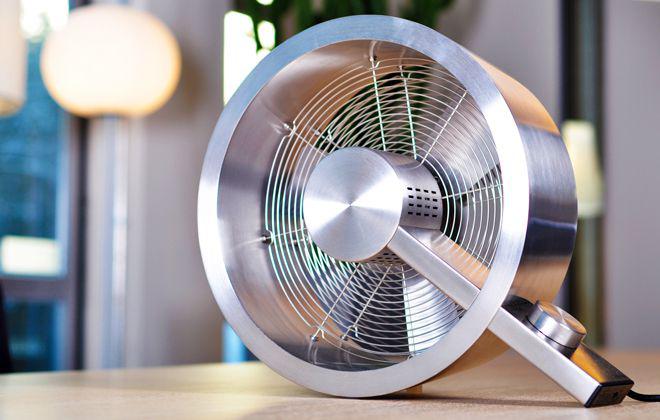
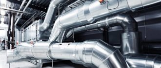
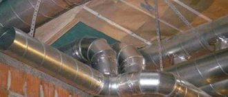
Axial fans are used separately and in air ducts, they work effectively where it is necessary to transfer large air masses at a relatively low pressure
The total fan pressure is determined by the formula Pп = Pп (out.) - Pп (in.)where:
- Pп (out) - total pressure at the outlet from the device;
- Pп (in.) - total pressure at the device inlet.
For the fan static pressure, the formula differs slightly.
It is written as Pst = Pst (out) - Pp (in), where:
- Рst (out) - static pressure at the outlet of the device;
- Pп (in.) - total pressure at the device inlet.
The static head does not reflect the required amount of energy to transfer it to the system, but serves as an additional parameter by which you can find out the total pressure. The last indicator is the main criterion when choosing a fan: both home and industrial. The drop in total head reflects the energy loss in the system.
The static pressure in the ventilation duct itself is obtained from the difference in static pressure at the inlet and outlet of the ventilation: Pst = Pst 0 - Pst 1... This is a minor parameter.
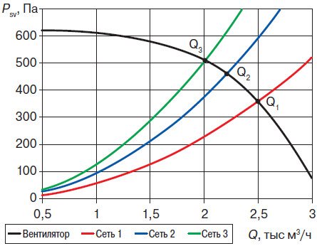
Designers provide parameters with little or no clogging in mind: the image shows the static pressure discrepancy of the same fan in different ventilation networks
The correct choice of a ventilation device includes the following nuances:
- calculation of air consumption in the system (m³ / s);
- selection of a device based on such a calculation;
- determination of the output speed for the selected fan (m / s);
- calculation of device Pp;
- measurement of static and dynamic head for comparison with total head.
To calculate the points for measuring the pressure, they are guided by the hydraulic diameter of the air duct. It is determined by the formula: D = 4F / P... F is the cross-sectional area of the pipe, and P is its perimeter. The distance for determining the measuring point at the inlet and outlet is measured with the number D.
2.2 TYPES OF PRESSURE
2.2.1 Absolute pressure.
Absolute pressure is the amount of pressure measured relative to an absolute vacuum.
2.2.2 Gauge pressure.
Gauge pressure is the value of pressure measured in such a way that the rms value of the barometric pressure is taken as zero.
2.2.3 Differential pressure.
Differential pressure is the difference between any two pressure values that are measured relative to a common value (e.g. the difference between two absolute pressures).
2.2.4 Static pressure.
Static pressure is the value of pressure measured in such a way that the influence of the speed of the current medium during the measurement has been completely eliminated.
2.2.5 Total pressure (brake pressure).
Total pressure (stagnation pressure) is the magnitude of the absolute or gauge pressure that could be measured at the moment when the fluid flow went into a state of rest and its kinetic energy was converted into an increase in enthalpy through an isentropic process, the transition from a fluid state to a state of inhibition ... When the liquid medium is in a stationary state, the values of static and total pressure are equal.
2.2.6 Velocity (Kinetic) pressure.
Velocity (Kinetic) pressure is the difference between total and static pressure for the same point in the fluid.
2.2.7 Total inlet pressure.
The total inlet pressure is the absolute total pressure at a gauge point located at the inlet (see paragraph 4.6.8). Unless otherwise indicated, total inlet pressure in this Methodology refers to the inlet pressure to the compressor.
2.2.8 Static inlet pressure.
The inlet static pressure is the absolute static pressure at a gauge point located at the inlet (see paragraph 4.6.7).
2.2.9 Total outlet pressure.
The outlet total pressure is the absolute total pressure at the gauge point located at the outlet (see paragraph 4.6.9). Unless otherwise indicated, total outlet pressure in this Methodology refers to the inlet pressure from the compressor.
2.2.1 Static outlet pressure.
The outlet static pressure is the absolute static pressure at a gauge point located downstream (see paragraph 4.6.7).
2.3 TYPES OF TEMPERATURES
2.3.1 Absolute temperature.
Absolute temperature is the temperature measured from absolute zero. It is measured in Rankine or Kelvin degrees. The Rankine temperature is the temperature in Fahrenheit plus 459.67 degrees, while the Kelvin temperature is the temperature in Celsius plus 273.15 degrees.
2.3.2 Static temperature.
Static temperature is a temperature value measured in such a way that the influence of the velocity of the flowing medium during measurements has been completely eliminated.
2.3.3 Total temperature (stagnation temperature).
The total temperature (stagnation temperature) is the temperature that would have been measured at the moment when the fluid flow went into a state of rest and its kinetic energy was converted into an increase in enthalpy through an isentropic process, the transition from a fluid state to a stagnation state. When the liquid medium is in a stationary state, the values of the static and total temperatures are equal.
2.3.4 Velocity (kinetic) temperature.
Velocity (Kinetic) temperature is the difference between total and static temperature for the same measuring point.
2.3.5 Total inlet temperature.
The inlet total temperature is the absolute total temperature at the measuring point located at the inlet (see paragraph 4.7.7). Unless otherwise indicated, the total inlet temperature in this Methodology refers to the compressor inlet temperature.
2.3.6
.
Static inlet temperature.
The static inlet temperature is the absolute static temperature at a measuring point located at the inlet.
2.3.7 Total outlet temperature.
The outlet total temperature is the absolute total temperature at the measuring point located at the outlet (see paragraph 4.7.8).Unless otherwise indicated, total outlet temperature in this Methodology refers to the temperature at the outlet of the compressor.
2.3.8 Static outlet temperature.
The static outlet temperature is the absolute static temperature at the measuring point located at the outlet.
2.4 OTHER PROPERTIES OF GAS (LIQUID)
2.4.1 Density.
Density is the mass per unit volume of a gas. The density of a gas is a thermodynamic characteristic and can be determined under conditions in which the values of the total pressure and temperature are known.
2.4.2 Specific volume.
Specific volume is the volume occupied by a unit of gas mass. The specific volume of a gas is a thermodynamic characteristic and can be determined under conditions in which the values of the total pressure and temperature are known.
2.4.3 Molecular weight.
Molecular weight is the mass of one molecule of a substance relative to the mass of a carbon -12 atom at 12,000.
2.4.4 Absolute viscosity.
Absolute viscosity is understood as the property of any fluid to show resistance to shear force (movement of one part of the fluid relative to another)
2.4.5 Kinematic viscosity.
The kinematic viscosity of a liquid is understood as the ratio of the absolute viscosity to the density of the liquid.
2.4.6 Specific heat at constant pressure.
The specific heat at constant pressure is the amount of enthalpy change for heating at constant pressure.
2.4.7 Specific heat at constant volume.
Specific heat at constant volume
Is the amount of change in internal energy for heating at constant volume.
2.4.8 Ratio of specific heat capacities.
The ratio of specific heats, denoted by the letter
k,
equal to cp / cv
2.4.9 Acoustic wave speed (speed of sound).
Pressure wave or acoustic wave with infinitesimal amplitude, which is described using an adiabatic and reversible (isentropic) process. The corresponding velocity of acoustic waves in any medium is calculated as follows:
2.4.10 Mach number of the fluid.
The Mach number of a fluid is the ratio of the speed of a body in a fluid to the speed of sound in that fluid.
2.5 MACHINE FEATURES
2.5.1 Performance.
Compressor capacity is a parameter of gas flow rate per unit of time, which is defined as the amount of gas sucked in from the external environment divided by the total density at the inlet. For a pneumatic machine, capacity is defined as the air flow through the inlet divided by the total inlet density. For machines with parallel flow, this definition should be applied to the individual stages.
2.5.2 Coefficient of consumption.
The flow coefficient is a dimensionless parameter that is calculated as the ratio of the mass flow rate of the compressed medium to the product of the density at the inlet, the rotational speed and the cube of the diameter at the tip of the blade, where the mass flow rate of the compressed medium is the total mass flow rate of the medium through the rotor part.
2.5.3 Degree of pressure rise.
The pressure rise is the ratio of the absolute total outlet pressure to the absolute total inlet pressure.
2.5.4 Increase in pressure.
Pressure rise refers to the ratio between the total outlet pressure and the total inlet pressure.
2.5.5 Temperature rise.
Temperature rise refers to the relationship between the total outlet temperature and the total inlet temperature.
2.5.6 Volume flow.
The volumetric flow rate, as understood in this Methodology, is equal to the mass flow rate divided by the total density. This parameter is used to calculate the volumetric flow factor.
2.5.7 Volumetric flow rate.
The volumetric flow rate is the ratio of the volumetric flows measured at two different points in the flow path.
2.5.8 Specific volume ratio.
The ratio of the specific volume is understood as the ratio of the specific volume of the medium at the inlet to the specific volume of the medium at the outlet.
2.5.9 Reynolds number for the unit.
The Reynolds number for the unit is given by the equation Rem =
Ub / υ,
Where
U -
this is the speed at the outer diameter of the end part of the first impeller blade or the diameter at the leading edge of the rotor blades of the first stage,
υ
Is the total kinematic viscosity of the gas at the compressor inlet, and
b
- characteristic size. For centrifugal compressors, parameter value
b
should be equal to the width of the outlet part on the outer diameter of the first stage impeller blades. For axial compressors, parameter value
b
is equal to the length of the chord-end of the first stage rotor blade. These variables must be expressed in consistent units of measurement in order to obtain a dimensionless value as a result of the calculation.
2.5.10 Mach number of the unit.
The Mach number of the unit is determined by the ratio of the peripheral speed of the blades at the point where the diameter along the tip edge of the blades of the first impeller is maximum in the case of centrifugal machines or at the point of the maximum section of the entrance edge of the rotor blades of the first stage in the case of machines with axial flow (
Approx. transl. Axial compressors
) to the speed of sound in a given gas under full input conditions.
NOTE: Not to be confused with the Mach number for a liquid medium.
2.5.11 Stage.
In the case of centrifugal compressors, the stage is the impeller and the corresponding structural elements of the stator flow path. The stage of an axial compressor consists of one row of rotor blades located on a disk or drum, and one row of subsequent guide vanes, as well as the corresponding structural elements of the flow path.
2.5.12 Cascade.
A cascade is understood as one or more stages having the same mass flow rate of the working medium without external heat exchange, with the exception of natural heat exchange through the housing.
2.5.13 Test volume.
The control volume is the area of the analyzed space, where the incoming and
the outgoing flows of the working medium, as well as the power consumption and heat transfer by means of heat conduction and radiation can be described using numerical (quantitative) methods. This area can be considered as an equilibrium state of material and energy balance.
2.5.14 Limit of stable compressor modes.
The limit of stable compressor modes is understood as such a load (capacity), after which the operation of the compressor becomes unstable. This occurs in the event of a restriction of flow, after which the compressor back pressure will exceed the pressure generated by the compressor itself, resulting in a stall phenomenon. The above will immediately reverse the flow direction, which will reduce the compressor back pressure. After this happens, normal compression will be restored in the unit and the cycle will be repeated.
2.5.15 Locking point.
The choke point is the point where the machine is run at a given speed and the flow is increased until maximum capacity is attained.
2.6 PERFORMANCE, POWER, AND PERFORMANCE RATES
The definitions below apply to this section.
2.6.1 Isoentropic compression.
In this Method, isentropic compression means a reversible process of adiabatic compression.
2.6.2 Isoentropic work (Head).
Isoentropic work (head) is the work that must be expended in order to effect isentropic compression of a unit mass of gas in a compressor from total pressure and total inlet temperature to total outlet pressure. The total pressure and total temperature are used to calculate the gas compression ratio and the change in the kinetic energy of the gas. Changes in the gravitational potential energy of the gas are assumed to be negligible.
2.6.3 Polytropic compression.
Polytropic compression is a reversible compression process from total inlet pressure and temperature to total outlet pressure and temperature. The total pressure and total temperature are used to calculate the gas compression ratio and the change in the kinetic energy of the gas. Changes in the gravitational potential energy of the gas are assumed to be negligible. The polytropic process is characterized by the invariability of the polytropic indicator.
2.6.4 Polytropic work (Head).
Polytropic work (head) is the work of the reverse cycle, which must be expended in order to carry out polytropic compression of a unit mass of gas in the compressor from total pressure and total inlet temperature to total pressure and total outlet temperature.
2.6.5 Gas work.
Gas work is the increase in the enthalpy per unit mass of the gas being compressed and cycling through the compressor from full pressure and full inlet temperature to full pressure and full outlet temperature.
2.6.6 Power of the gas flow.
Gas power is the power imparted to the gas flow. It is equal to the product of the mass flow rate of the compressed medium and the work of the gas plus the heat loss from the compression of the gas.
2.6.7 Isoentropic efficiency.
Isentropic efficiency is the ratio of isentropic work to gas work.
2.6.8 Polytropic efficiency.
Polytropic efficiency is the ratio of polytropic work to gas work.
2.6.9 Shaft power (effective power).
Shaft power (effective power) refers to the power imparted to the compressor shaft. It is the sum of the power of the gas flow and the mechanical losses in the compressor.
2.6.10 Coefficient of isentropic work.
The coefficient of isentropic work is the dimensionless ratio of the value of isentropic work to the sum of the squares of the circumferential velocities of the tip edges of the rotor blades of all stages of a given cascade.
2.6.1 1 Coefficient of polytropic work.
The coefficient of polytropic work is the dimensionless ratio of the magnitude of polytropic work to the sum of the squares of the circumferential velocities of the tip edges of the rotor blades of all stages of a given cascade.
2.6.1 2 Mechanical losses.
Mechanical loss is understood as the total energy absorbed as a result of the action of friction force by such components of the mechanism as wheels or gears of gears, bearings and seals.
2.6.13 Coefficient of work expended.
The coefficient of the work expended is the dimensionless ratio of the magnitude of the increase in enthalpy to the sum of the squares of the circumferential velocities of the tip edges of the rotor blades of all stages of a given cascade.
2.6.14 Coefficient of total work expended.
The coefficient of the total expended work is the dimensionless ratio of the value of the total expended work of the gas to the sum of the squares of the circumferential velocities of the tip edges of the rotor blades of all stages of a given cascade.
2.7 OTHER DEFINITIONS
2.7.1 Reynolds number for a liquid medium.
The Reynolds number for a liquid medium is the Reynolds number for a gas flow moving inside a pipe. The Reynolds number can be obtained from the equation Re =
VD / υ,
where the parameters of velocity, characteristic length and static kinematic viscosity are used in the equation as follows:
complete thermodynamic conditions. Subscripts that appear in such equations should be interpreted as follows:
under speed V
means the average speed at the point of pressure measurement,
D -
this is the inner diameter of the pipe at the point of pressure measurement, and the value of the kinematic viscosity of the medium
υ
taken into account the static temperature and pressure values at the measuring point. Information on pressure and temperature measuring points used to measure flow parameters will be presented in Section 4 and accompanying illustrations.The variables when calculating the Reynolds number must be expressed in consistent units of measurement in order to obtain a dimensionless value as a result of the calculation.
2.7.2 Dimensional constant.
Dimensional constant,
gc
, is required to be reflected in the calculation of units of measure for mass, time and force. The dimensional constant is 32.174 ft-lbm / lbf • sec2. The numerical value is not influenced locally by the acceleration of gravity.
2.7.3 Specified operating conditions.
Specified operating conditions are those conditions for which the performance of the compressor is to be determined. See paragraphs 6.2.3 and 6.2.4.
2.7.4 Test conditions.
Test conditions are those operating conditions that prevail in terms of the duration of the test. See paragraphs 6.2.7 and 6.2.8.
2.7.5 Equivalence.
It is understood that the specified operating conditions and test conditions in the context of this Methodology demonstrate equivalence when, for the same value of the flow coefficient, the ratios of three dimensionless parameters (specific volume coefficient, Mach number of the unit and Reynolds number of the unit) are within the boundary values, given in Table. 3.2.
2.7.6 Raw data.
Raw data refers to the readings of the measuring instruments obtained during the tests.
2.7.7 Instrument indication.
The reading of the device is understood as the average value of individual measurements (raw data), taking into account the corrections at any given measuring point.
2.7.8 Checkpoint.
A reference point is three or more readings that have been averaged and are within a specified tolerance.
2.7.9 Deviation.
Deviation is the difference between the maximum and minimum readings divided by the average of all readings, expressed as a percentage.
contents .. 1 2 3 ..
How to calculate ventilation pressure?
The total inlet head is measured in the cross-section of the ventilation duct, located at a distance of two hydraulic duct diameters (2D). Ideally, there should be a straight piece of duct with a length of 4D and unperturbed flow in front of the measurement site.
In practice, the above conditions are rare, and then a honeycomb is installed in front of the desired place, which straightens the air flow.
Then a total pressure receiver is introduced into the ventilation system: at several points in the section in turn - at least 3. The average result is calculated from the obtained values. For fans with a free inlet, the inlet Pp corresponds to the ambient pressure, and the excess pressure in this case is equal to zero.
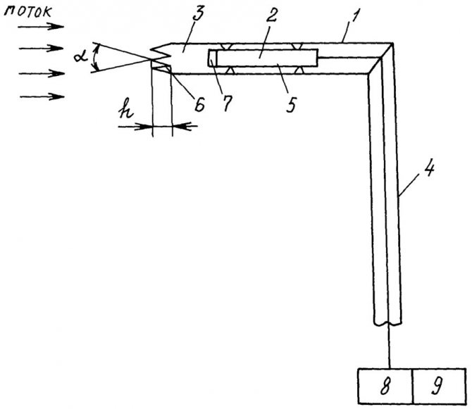
Diagram of the total pressure receiver: 1 - receiving tube, 2 - pressure transducer, 3 - braking chamber, 4 - holder, 5 - annular channel, 6 - leading edge, 7 - inlet grating, 8 - normalizer, 9 - output signal recorder, α - angle at the tops, h - depth of the valleys
If you measure a strong air flow, then the pressure should determine the speed, and then compare it with the cross-sectional size. The higher the speed per unit area and the larger the area itself, the more efficient the fan.
Full pressure at the outlet is a complex concept. The outflow stream has a non-uniform structure, which also depends on the mode of operation and the type of device. The outlet air has zones of return movement, which complicates the calculation of pressure and speed.
It will not be possible to establish a regularity for the time of occurrence of such a movement. The inhomogeneity of the flow reaches 7-10 D, but the indicator can be reduced by rectifying gratings.
The Prandtl tube is an improved version of the Pitot tube: receivers are produced in 2 versions - for speeds less and more than 5 m / s
Sometimes at the outlet of the ventilation device there is a rotary elbow or a tear-off diffuser. In this case, the flow will be even more inhomogeneous.
The head is then measured according to the following method:
- The first section is selected behind the fan and scanned with a probe. At several points, the average total head and productivity are measured. The latter is then compared with the input performance.
- Further, an additional section is selected - in the nearest straight section after exiting the ventilating device. From the beginning of such a fragment, 4-6 D are measured, and if the length of the section is less, then a section is chosen at the most distant point. Then take the probe and determine the productivity and the average total head.
The calculated losses in the section after the fan are subtracted from the average total pressure at the additional section. The total outlet pressure is obtained.
Then the performance is compared at the inlet, as well as at the first and additional sections at the outlet. The input indicator should be considered correct, and one of the outputs should be considered closer in value.
There may not be a straight line segment of the required length. Then choose a cross-section that divides the area to be measured into parts with a ratio of 3 to 1. Closer to the fan should be the larger of these parts. Measurements should not be made in diaphragms, dampers, outlets and other connections with air disturbance.
Pressure drops can be recorded by pressure gauges, pressure gauges in accordance with GOST 2405-88 and differential pressure gauges in accordance with GOST 18140-84 with an accuracy class of 0.5-1.0
In the case of roof fans, Pp is measured only at the inlet, and the static is determined at the outlet. The high-speed flow after the ventilation device is almost completely lost.
We also recommend reading our material on the choice of pipes for ventilation.
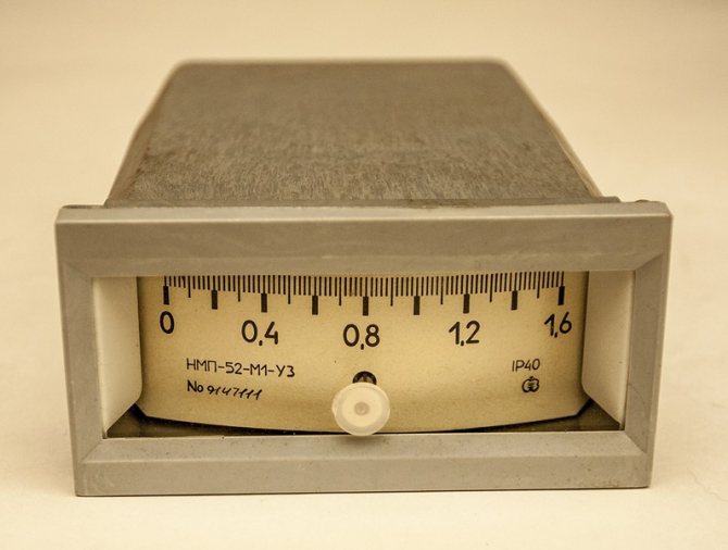
What pressure does the pressure gauge show?
This physical quantity characterizes the degree of compression of the medium, in our case, the liquid heat carrier pumped into the heating system. To measure any physical quantity means to compare it with some standard. The process of measuring the pressure of a liquid heat carrier with any mechanical manometer (vacuum gauge, manovacuum gauge) is a comparison of its current value at the point of the device with atmospheric pressure, which plays the role of a measurement standard.
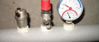
Sensitive elements of pressure gauges (tubular springs, diaphragms, etc.) are themselves under the influence of the atmosphere. The most common spring-loaded pressure gauge has a sensing element, which is one coil of a tubular spring (see the item in the figure below). The upper end of the tube is sealed and connected by a leash 4 with a toothed sector 5, meshed with a gear 3, on the shaft of which arrow 2 is mounted.
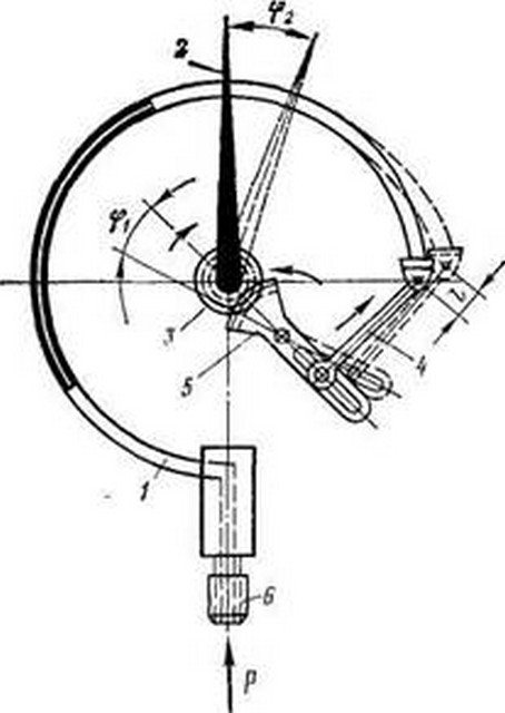
Spring pressure gauge device.
The initial position of the spring tube 1, corresponding to the zero of the measurement scale, is determined by the deformation of the spring shape by the pressure of atmospheric air filling the manometer body. The liquid entering the inside of the tube 1 tends to additionally deform it, raising the upper sealed end higher by a distance l proportional to its internal pressure. The displacement of the end of the spring tube is converted by the transmission mechanism into a turn of the arrow.
The angle φ of deflection of the latter is proportional to the difference in the total pressure of the liquid in the spring tube 1 and the local atmospheric pressure. The pressure measured by such a device is called gauge or gauge. Its starting point is not the absolute zero of the value, which is equivalent to the absence of air around tube 1 (vacuum), but the local atmospheric pressure.
Known manometers showing the absolute (without deducting atmospheric) pressure of the environment. The complex device plus the high price hinders the widespread use of such devices in heating systems.
The values of the pressures indicated in the passports of any boilers, pumps, shut-off (control) valves, pipelines are precisely gauge (excess).The excess value measured by manometers is used in hydraulic (thermal) calculations of heating systems (equipment).
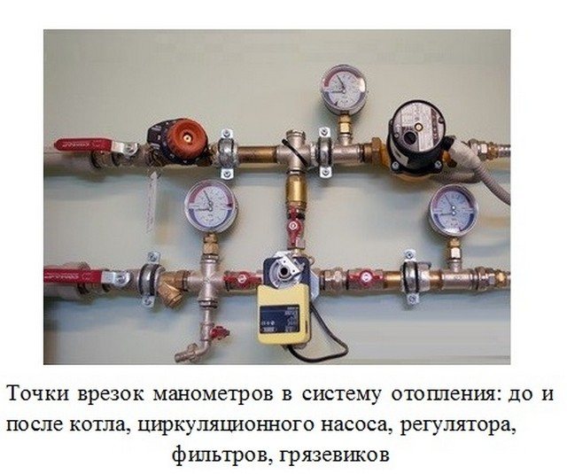
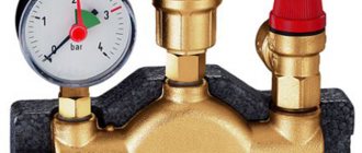
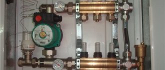
Pressure gauges in the heating system.
Features of calculating the pressure
Measuring pressure in air is complicated by its rapidly changing parameters. Manometers should be purchased electronic with the function of averaging the results obtained per unit of time. If the pressure jumps sharply (pulsates), dampers will come in handy, which smooth out the differences.
The following patterns should be remembered:
- total pressure is the sum of static and dynamic;
- the total fan head must be equal to the pressure loss in the ventilation network.
Measuring the static outlet pressure is straightforward. To do this, use a tube for static pressure: one end is inserted into the differential pressure gauge, and the other is directed into the section at the outlet of the fan. The static head is used to calculate the flow rate at the outlet of the ventilating device.
The dynamic head is also measured with a differential pressure gauge. Pitot-Prandtl tubes are connected to its connections. To one contact - a tube for full pressure, and to the other - for static. The result will be equal to the dynamic pressure.
To find out the pressure loss in the duct, the flow dynamics can be monitored: as soon as the air velocity rises, the resistance of the ventilation network rises. The pressure is lost due to this resistance.

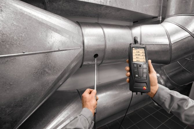
Anemometers and hot-wire anemometers measure the flow velocity in the duct at values up to 5 m / s or more, the anemometer should be selected in accordance with GOST 6376-74
With an increase in the fan speed, the static pressure drops, and the dynamic pressure increases in proportion to the square of the increase in air flow. The total pressure will not change.
With a properly selected device, the dynamic head changes in direct proportion to the square of the flow rate, and the static head changes in inverse proportion. In this case, the amount of air used and the load of the electric motor, if they grow, is insignificant.
Some requirements for the electric motor:
- low starting torque - due to the fact that the power consumption changes in accordance with the change in the number of revolutions supplied to the cube;
- large stock;
- work at maximum power for greater savings.
The fan power depends on the total head as well as the efficiency and air flow rate. The last two indicators correlate with the throughput of the ventilation system.
At the design stage, you will have to prioritize. Take into account costs, losses of useful volume of premises, noise level.
Volume and flow rate
The volume of liquid passing through a specific point at a given time is considered as a flow volume or flow rate. The flow volume is usually expressed in liters per minute (l / min) and is related to the relative pressure of the fluid. For example, 10 liters per minute at 2.7 atm.
Flow velocity (fluid velocity) is defined as the average velocity at which a fluid moves past a given point. Typically expressed in meters per second (m / s) or meters per minute (m / min). Flow rate is an important factor when calibrating hydraulic lines.
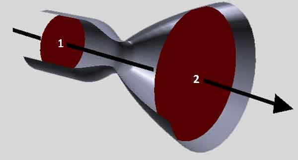
The volume and flow rate of a liquid are traditionally considered "related" metrics. With the same transmission volume, the speed can vary depending on the cross-section of the passage
Volume and flow rate are often considered at the same time. All other things being equal (with a constant injection volume), the flow rate increases as the section or pipe size decreases, and the flow rate decreases as the section increases.
Thus, a slowdown in the flow rate is observed in wide parts of the pipelines, and in narrow places, on the contrary, the speed increases. At the same time, the volume of water passing through each of these control points remains unchanged.
Bernoulli's principle
The well-known Bernoulli principle is built on the logic when the rise (fall) of the pressure of a fluid fluid is always accompanied by a decrease (increase) in velocity. Conversely, an increase (decrease) in fluid velocity leads to a decrease (increase) in pressure.
This principle is at the heart of a number of common plumbing phenomena. As a trivial example, Bernoulli's principle is “guilty” of the shower curtain being “pulled inward” when the user turns on the water.
The pressure difference outside and inside causes a force on the shower curtain. With this force, the curtain is pulled inward.
Another good example is a perfume bottle with a spray, where the press of a button creates a low pressure area due to the high air velocity. And the air carries the liquid along with it.
Bernoulli's principle also shows why windows in a house have the ability to spontaneously break in hurricanes. In such cases, the extremely high speed of air outside the window leads to the fact that the pressure outside becomes much less than the pressure inside, where the air remains practically motionless.
The significant difference in strength simply pushes the windows outward, causing the glass to shatter. Therefore, when a strong hurricane is approaching, in essence, you should open the windows as wide as possible to equalize the pressure inside and outside the building.
And a couple more examples when the Bernoulli principle works: the rise of an airplane followed by flight using the wings and the movement of "curved balls" in baseball.
In both cases, a difference in the speed of air passing by the object from above and below is created. For aircraft wings, the difference in speed is created by the movement of the flaps; in baseball, by the presence of a wavy edge.
Pressure units
Pressure is an intense physical quantity. SI pressure is measured in pascals; The following units also apply:
| Pressure | |||||||||
| mm water Art. | mmHg Art. | kg / cm 2 | kg / m 2 | m water. Art. | |||||
| 1 mm water Art. | |||||||||
| 1 mmHg Art. | |||||||||
| 1 bar | |||||||||
Comments:
The basis for the design of any engineering networks is the calculation. In order to correctly design a network of supply or exhaust air ducts, it is necessary to know the parameters of the air flow. In particular, it is necessary to calculate the flow rate and pressure loss in the duct for the correct selection of the fan power.
In this calculation, an important role is played by such a parameter as the dynamic pressure on the walls of the duct.
Pressure drops
To compensate for the differences, additional equipment is built into the circuit:
- expansion tank;
- valve for emergency release of the coolant;
- air outlets.
Air Test - The test pressure of the heating system is increased to 1.5 bar, then released to 1 bar and left for five minutes. In this case, losses should not exceed 0.1 bar.
Testing with water - increase the pressure to at least 2 bar. Perhaps more. Depends on operating pressure. The maximum operating pressure of the heating system must be multiplied by 1.5. In five minutes, losses should not exceed 0.2 bar.
Panel
Cold hydrostatic testing - 15 minutes with a pressure of 10 bar, losses no more than 0.1 bar. Hot testing - raising the temperature in the circuit to 60 degrees for seven hours.
Test with water at 2.5 bar. Additionally, water heaters (3-4 bars) and pumping units are checked.
Heating network
The permissible pressure in the heating system gradually increases to a level higher than the operating pressure by 1.25, but not less than 16 bar.
Based on the test results, an act is drawn up, which is a document confirming the performance characteristics declared in it. These include, in particular, the operating pressure.
To the question Static pressure is atmospheric pressure or what? given by the author Edya Bondarchuk
the best answer is
I urge everyone not to copy overly clever encyclopedia articles when people ask simple questions.Going physics is not needed here. The word "static" means in the literal sense - constant, unchanging in time. When you pump a soccer ball, the pressure inside the pump is not static, but different every second. And when you pump up, there is constant air pressure inside the ball - static. And atmospheric pressure is static in principle, although if you dig deeper, it is not, it still changes insignificantly over the course of days and even hours. In short, there is nothing abstruse here. Static means permanent and doesn't mean anything else. When you say hello to guys, please! Shock from hand to hand. Well, it happened with everyone. They say "static electricity". Correctly! At this moment, a static charge (constant) has accumulated in your body. When you touch another person, half of the charge passes to him in the form of a spark. That's it, I will not ship any more. In short, "static" = "permanent", for all occasions. Comrades, if you do not know the answer to the question, and even more so did not study physics at all, you do not need to copy articles from encyclopedias !! just like you’re wrong, you didn’t come to the first lesson and didn’t ask you for the Bernouli formulas, right? they began to chew on what pressure, viscosity, formulas, etc., etc. are, but when you come and give you exactly as you said, the person is disgusted with it. What curiosity about knowledge if you don't understand the symbols in the same equation? It's easy to tell someone who has some kind of base, so you're completely wrong!
Answer from roast beef
[newbie] Atmospheric pressure contradicts the MKT structure of gases and refutes the existence of chaotic movement of molecules, the result of which is the pressure on the surfaces bordering with the gas. The pressure of gases is predetermined by the mutual repulsion of the molecules of the same name. The repulsion voltage is equal to the pressure. If we consider the column of the atmosphere as a solution of gases 78% nitrogen and 21% oxygen and 1% others, then atmospheric pressure can be considered as the sum of the partial pressures of its components. The forces of mutual repulsion of molecules equalize the distances between the like-named on the isobars. Presumably, oxygen molecules do not have repulsive forces with the others. So from the assumption that the molecules of the same name are repelled with the same potential, this explains the equalization of the concentrations of gases in the atmosphere and in a closed vessel.
Answer from Huck Finn
[guru] Static pressure is that which is created by the force of gravity. Water under its own weight presses on the walls of the system with a force proportional to the height to which it rises. From 10 meters, this figure is equal to 1 atmosphere. In statistical systems, flow blowers are not used, and the coolant circulates through pipes and radiators by gravity. These are open systems. The maximum pressure in an open heating system is about 1.5 atmospheres. In modern construction, such methods are practically not used, even when installing autonomous circuits of country houses. This is due to the fact that for such a circulation scheme, pipes with a large diameter must be used. It is not aesthetically pleasing and expensive. Pressure in a closed heating system: The dynamic pressure in the heating system can be adjusted The dynamic pressure in a closed heating system is created by artificially increasing the flow rate of the heating medium using an electric pump. For example, if we are talking about high-rise buildings, or large highways. Although, now even in private houses, pumps are used when installing heating. Important! We are talking about overpressure, excluding atmospheric pressure. Each of the heating systems has its own permissible tensile strength. In other words, it can withstand different loads. To find out what is the working pressure in a closed heating system, it is necessary to add the dynamic pressure generated by the pumps to the static pressure created by the water column.For the system to work properly, the pressure gauge must be stable. A pressure gauge is a mechanical device that measures the pressure with which water moves in a heating system. It consists of a spring, an arrow and a scale. Pressure gauges are installed in key locations. Thanks to them, you can find out what the operating pressure is in the heating system, as well as identify malfunctions in the pipeline during diagnostics (hydraulic tests).
Answer from capable
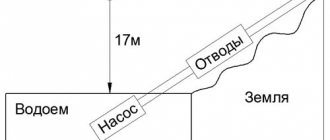
[guru] In order to pump liquid to a given height, the pump must overcome static and dynamic pressure. Static pressure is the pressure caused by the height of the liquid column in the pipeline, i.e. the height to which the pump must lift the liquid .. Dynamic pressure is the sum of hydraulic resistances due to the hydraulic resistance of the pipeline wall itself (taking into account the wall roughness, contamination, etc.), and local resistances (pipeline bends, valves, gate valves, etc.). ).
Answer from Eurovision
[guru] Atmospheric pressure - the hydrostatic pressure of the atmosphere on all objects in it and the earth's surface. Atmospheric pressure is created by the gravitational attraction of air to the Earth. And static pressure - I have not met the current concept. And as a joke, we can assume that this is due to the laws of electric forces and the electric power of attraction. Maybe this? - Electrostatics - a branch of physics that studies the electrostatic field and electric charges. Electrostatic (or Coulomb) repulsion occurs between like-charged bodies, and electrostatic attraction between like-charged bodies. The phenomenon of repulsion of like charges underlies the creation of an electroscope - a device for detecting electric charges. Statics (from the Greek στατός, "motionless"): A state of rest at a certain moment (book). For example: Describe a static phenomenon; (adj.) static. A branch of mechanics in which the conditions of equilibrium of mechanical systems are studied under the action of forces and moments applied to them. So I have not met the concept of static pressure.
Answer from Andrey Khalizov
[guru] Pressure (in physics) - the ratio of the force normal to the surface of interaction between bodies, to the area of this surface or in the form of the formula: P = F / S. Static (from the word Static (from the Greek στατός, "stationary" "constant")) pressure is a time-constant (unchanging) application of a force normal to the surface of interaction between bodies. Atmospheric (barometric) pressure is the hydrostatic pressure of the atmosphere on all objects in it and on the earth's surface. Atmospheric pressure is created by the gravitational attraction of air to the Earth. On the earth's surface, atmospheric pressure varies from place to place and over time. Atmospheric pressure decreases with height, since it is created only by the overlying layer of the atmosphere. The dependence of pressure on altitude is described by the so-called. That is, these are two different concepts.
Bernoulli's Law on Wikipedia Look at the Wikipedia article about Bernoulli's Law
Comments:
The basis for the design of any engineering networks is the calculation. In order to correctly design a network of supply or exhaust air ducts, it is necessary to know the parameters of the air flow. In particular, it is necessary to calculate the flow rate and pressure loss in the duct for the correct selection of the fan power.
In this calculation, an important role is played by such a parameter as the dynamic pressure on the walls of the duct.