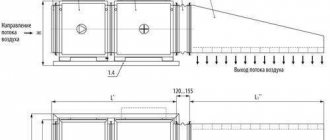
The purpose of the aerodynamic calculation is to determine the dimensions of the cross-sections and the pressure losses in sections of the system and in the system as a whole. The calculation must take into account the following provisions.
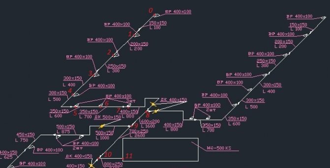
1. On the axonometric diagram of the system, the costs and two sections are marked.
2. The main direction is selected and the sections are numbered, then the branches are numbered.
3. According to the permissible speed on the sections of the main direction, the cross-sectional areas are determined:
The result obtained is rounded to standard values, which are calculated, and the diameter d or the dimensions a and b of the channel are found from the standard area.
In the reference literature, up to the aerodynamic calculation tables, a list of standard dimensions for the areas of round and rectangular air ducts is given.
* Note: small birds caught in the torch zone at a speed of 8 m / s stick to the grate.
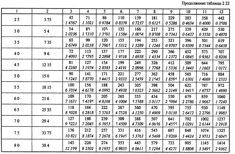
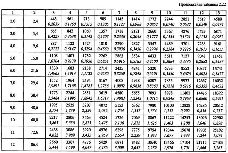
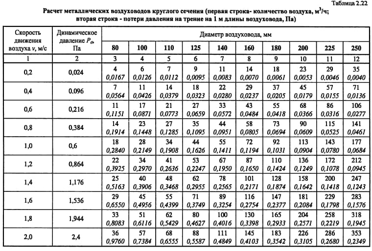
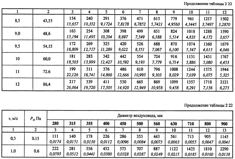
4. From the tables of aerodynamic calculation for the selected diameter and flow rate in the section determine the calculated values of the speed υ, specific friction losses R, dynamic pressure P dyn. If necessary, then determine the coefficient of relative roughness β w.
5. On the site, the types of local resistances, their coefficients ξ and the total value ∑ξ are determined.
6. Find the pressure loss in local resistances:
Z = ∑ξ · P dyn.
7. Determine the pressure loss due to friction:
∆Р tr = R · l.
8. Calculate the pressure loss in this area using one of the following formulas:
∆Р uch = Rl + Z,
∆Р uch = Rlβ w + Z.
The calculation is repeated from point 3 to point 8 for all sections of the main direction.
9. Determine the pressure loss in the equipment located on the main direction ∆Р about.
10. Calculate the system resistance ∆Р с.
11. For all branches, repeat the calculation from point 3 to point 9, if the branches have equipment.
12. Link the branches with parallel sections of the line:
. (178)
The taps should have a resistance slightly greater than or equal to that of the parallel line section.
Rectangular air ducts have a similar calculation procedure, only in paragraph 4 by the value of the speed found from the expression:
,
and the equivalent diameter in speed d υ are found from the tables of aerodynamic calculation of the reference literature specific friction losses R, dynamic pressure P dyn, and L table табл L uch.
Aerodynamic calculations ensure the fulfillment of condition (178) by changing the diameters on the branches or by installing throttling devices (throttle valves, dampers).
For some local resistances, the value of ξ is given in the reference literature as a function of speed. If the value of the calculated speed does not coincide with the tabulated one, then ξ is recalculated according to the expression:
For unbranched systems or systems of small sizes, the branches are tied up not only with the help of throttle valves, but also with diaphragms.
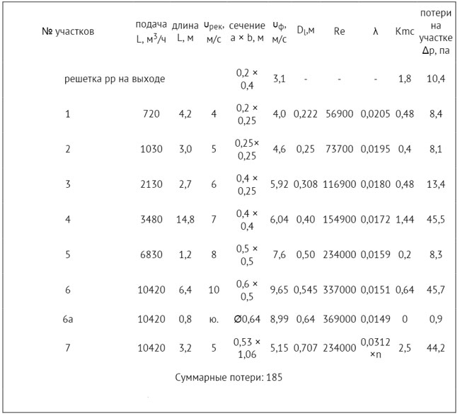
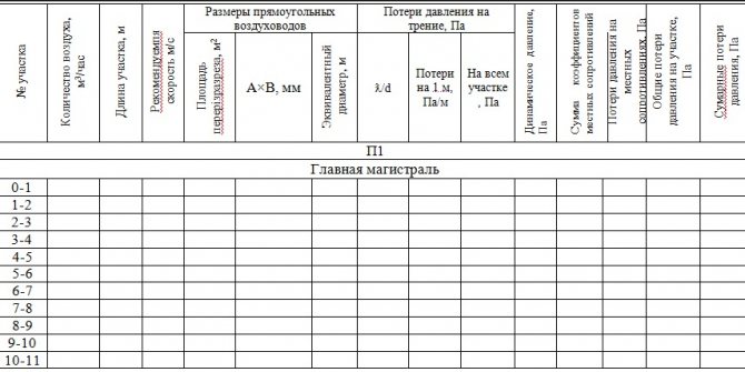
For convenience, the aerodynamic calculation is performed in tabular form.
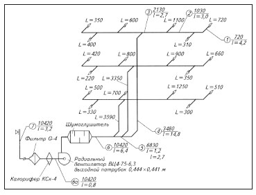
Let us consider the procedure for aerodynamic calculation of an exhaust mechanical ventilation system.
| No. of plot | L, m 3 / h | F, m 2 | V, m / s | a × b, mm | D e, mm | β w | R, Pa / m | l, m | Rlβ w, Pa | Local resistance type | ∑ξ | R d, Pa | Z = ∑ξ P d Pa | ΔР = Rl + Z, Pa |
| Location on | on magistral | |||||||||||||
| 1-2 | 0,196 | 11,71 | — | 2,56 | 11,93 | 30,5 | 0.42-ext. extension 0.38-confuser 0.21-2 elbows 0.35-tee | 1,57 | 83,63 | 131,31 | 282,85 | 282,85 | ||
| 2-3 | 0,396 | 11,59 | — | 1,63 | 15,35 | 25,0 | 0.21-3 branch 0.2-tee | 0,83 | 81,95 | 68,02 | 93,04 | 375,89 | ||
| 3-4 | 0,502 | 10,93 | — | 1,25 | 2,76 | 3,5 | 0.21-2 tap 0.1-transition | 0,52 | 72,84 | 37,88 | 41,33 | 417,21 | ||
| 4-5 | 0,632 | 8,68 | 795x795 | 2,085 | 0,82 | 3,50 | 6,0 | 5,98 | 423,20 | |||||
| 2″-2 | 0,196 | 11,71 | — | 2,56 | 6,27 | 16,1 | 0.42-ext.extension 0.38-confuser 0.21-2 branch 0.98-tee | 1,99 | 83,63 | 166,43 | 303,48 | |||
| 6-7 | 0,0375 | 5,50 | 250x200 | — | 1,8-mesh | 1,80 | 18,48 | 33,26 | 33,26 | |||||
| 0,078 | 10,58 | — | 3,79 | 5,54 | 21,0 | 1.2-turn 0.17-tee | 1,37 | 68,33 | 93,62 | 114,61 | ||||
| 7-3 | 0,078 | 11,48 | — | 4,42 | 5,41 | 23,9 | 0.17-elbow 1.35-tee | 1,52 | 80,41 | 122,23 | 146,14 | |||
| 7″-7 | 0,015 | 4,67 | 200x100 | — | 1,8-mesh | 1,80 | 13,28 | 23,91 | 23,91 | |||||
| 0,0123 | 5,69 | — | 3,80 | 1,23 | 4,7 | 1.2-turn 5.5-tee | 6,70 | 19,76 | 132,37 | 137,04 |
Tees have two resistances - per passage and per branch, and they always refer to areas with a lower flow rate, i.e. either to the flow area or to the branch. When calculating branches in column 16 (table, page 88), a dash.
The main requirement for all types of ventilation systems is to ensure the optimal frequency of air exchange in rooms or specific work areas. Taking this parameter into account, the inner diameter of the duct is designed and the fan power is selected. In order to guarantee the required efficiency of the ventilation system, the calculation of the head pressure losses in the ducts is carried out, these data are taken into account when determining the technical characteristics of the fans. Recommended air flow rates are shown in Table 1.
Tab. No. 1. Recommended air speed for different rooms
| Appointment | Basic requirement | ||||
| Noiselessness | Min. head loss | ||||
| Trunk channels | Main channels | Branches | |||
| Inflow | Hood | Inflow | Hood | ||
| Living spaces | 3 | 5 | 4 | 3 | 3 |
| Hotels | 5 | 7.5 | 6.5 | 6 | 5 |
| Institutions | 6 | 8 | 6.5 | 6 | 5 |
| Restaurants | 7 | 9 | 7 | 7 | 6 |
| The shops | 8 | 9 | 7 | 7 | 6 |
Based on these values, the linear parameters of the ducts should be calculated.
Algorithm for calculating the loss of air pressure
The calculation must begin with drawing up a diagram of the ventilation system with the obligatory indication of the spatial arrangement of air ducts, the length of each section, ventilation grilles, additional equipment for air purification, technical fittings and fans. Losses are determined first for each separate line, and then they are summed up. For a separate technological section, the losses are determined using the formula P = L × R + Z, where P is the air pressure loss in the calculated section, R is the losses per linear meter of the section, L is the total length of the air ducts in the section, Z is the losses in the additional fittings of the system ventilation.
To calculate the pressure loss in a circular duct, the formula Ptr is used. = (L / d × X) × (Y × V) / 2g. X is the tabular coefficient of air friction, depends on the material of the air duct, L is the length of the calculated section, d is the diameter of the air duct, V is the required air flow rate, Y is the air density taking into account the temperature, g is the acceleration of falling (free). If the ventilation system has square ducts, then table No. 2 should be used to convert round values to square ones.
Tab. No. 2. Equivalent diameters of round ducts for square
| 150 | 200 | 250 | 300 | 350 | 400 | 450 | 500 | |
| 250 | 210 | 245 | 275 | |||||
| 300 | 230 | 265 | 300 | 330 | ||||
| 350 | 245 | 285 | 325 | 355 | 380 | |||
| 400 | 260 | 305 | 345 | 370 | 410 | 440 | ||
| 450 | 275 | 320 | 365 | 400 | 435 | 465 | 490 | |
| 500 | 290 | 340 | 380 | 425 | 455 | 490 | 520 | 545 |
| 550 | 300 | 350 | 400 | 440 | 475 | 515 | 545 | 575 |
| 600 | 310 | 365 | 415 | 460 | 495 | 535 | 565 | 600 |
| 650 | 320 | 380 | 430 | 475 | 515 | 555 | 590 | 625 |
| 700 | 390 | 445 | 490 | 535 | 575 | 610 | 645 | |
| 750 | 400 | 455 | 505 | 550 | 590 | 630 | 665 | |
| 800 | 415 | 470 | 520 | 565 | 610 | 650 | 685 | |
| 850 | 480 | 535 | 580 | 625 | 670 | 710 | ||
| 900 | 495 | 550 | 600 | 645 | 685 | 725 | ||
| 950 | 505 | 560 | 615 | 660 | 705 | 745 | ||
| 1000 | 520 | 575 | 625 | 675 | 720 | 760 | ||
| 1200 | 620 | 680 | 730 | 780 | 830 | |||
| 1400 | 725 | 780 | 835 | 880 | ||||
| 1600 | 830 | 885 | 940 | |||||
| 1800 | 870 | 935 | 990 |
The horizontal is the height of the square duct, and the vertical is the width. The equivalent value of the circular section is at the intersection of the lines.
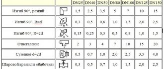
The air pressure losses in the bends are taken from table no. 3.
Tab. No. 3. Pressure loss at bends
To determine the pressure loss in the diffusers, the data from Table 4 are used.
Tab. No. 4. Pressure loss in diffusers
Table 5 gives a general diagram of losses in a straight section.
Tab. No. 5. Diagram of air pressure losses in straight air ducts
All individual losses in this section of the duct are summed up and corrected with table No. 6. Tab. No. 6. Calculation of the decrease in flow pressure in ventilation systems
During design and calculations, existing regulations recommend that the difference in the magnitude of pressure losses between individual sections does not exceed 10%. The fan should be installed in the area of the ventilation system with the highest resistance, the most distant air ducts should have the lowest resistance. If these conditions are not met, then it is necessary to change the layout of air ducts and additional equipment, taking into account the requirements of the provisions.
To determine the dimensions of the sections on any of the sections of the air distribution system, it is necessary to make an aerodynamic calculation of the air ducts. The indicators obtained with this calculation determine the operability of both the entire projected ventilation system and its individual sections.
To create a comfortable environment in a kitchen, a separate room or a room as a whole, it is necessary to ensure the correct design of the air distribution system, which consists of many details. An important place among them is occupied by the air duct, the determination of the quadrature of which affects the value of the air flow rate and the noise level of the ventilation system as a whole. To determine these and a number of other indicators will allow aerodynamic calculation of air ducts.
We deal with the general ventilation calculation
When making an aerodynamic calculation of air ducts, you must take into account all the characteristics of the ventilation shaft (these characteristics are given below in the form of a list).
- Dynamic pressure (to determine it, the formula is used - DPE? / 2 = P).
- Air mass consumption (it is denoted by the letter L and is measured in cubic meters per hour).
- Pressure loss due to air friction against the inner walls (denoted by the letter R, measured in pascals per meter).
- The diameter of the ducts (to calculate this indicator, the following formula is used: 2 * a * b / (a + b); in this formula, the values a, b are the dimensions of the channel section and are measured in millimeters).
- Finally, speed is V, measured in meters per second, as we mentioned earlier.
>
As for the direct sequence of actions in the calculation, it should look something like the following.
Step one. First, determine the required channel area, for which the following formula is used:
I / (3600xVpek) = F.
Let's deal with the values:
- F in this case is, of course, the area, which is measured in square meters;
- Vpek is the desired speed of air movement, which is measured in meters per second (for canals, a speed of 0.5-1.0 meters per second is taken, for mines - about 1.5 meters).
Step two.
Next, you need to select a standard section that would be as close as possible to the indicator F.
Step three.
The next step is to determine the appropriate duct diameter (denoted by the letter d).
Step four.
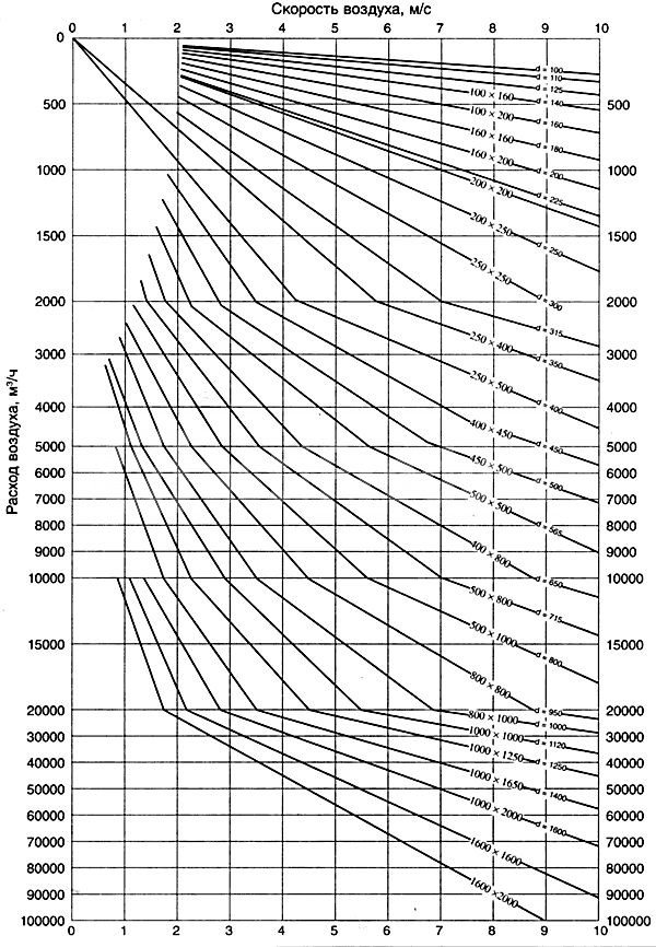
Then the remaining indicators are determined: pressure (denoted as P), speed of movement (abbreviated V) and, therefore, decrease (abbreviated R). For this, it is necessary to use the nomograms according to d and L, as well as the corresponding coefficient tables.
Step five
... Using already other tables of coefficients (we are talking about indicators of local resistance), it is required to determine how much the effect of air will decrease due to local resistance Z.
Step six.
At the last stage of calculations, it is necessary to determine the total losses at each separate section of the ventilation line.
Pay attention to one important point! So, if the total losses are lower than the already existing pressure, then such a ventilation system can be considered effective. But if the losses exceed the pressure indicator, then it may be necessary to install a special throttle diaphragm in the ventilation system. Thanks to this diaphragm, the excess head will be extinguished.
We also note that if the ventilation system is designed to serve several rooms at once, for which the air pressure must be different, then during calculations it is necessary to take into account the vacuum or back pressure indicator, which must be added to the total loss indicator.
Video - How to make calculations using the "VIX-STUDIO" program
Aerodynamic calculation of air ducts is considered a mandatory procedure, an important component of the planning of ventilation systems.Thanks to this calculation, you can find out how effectively the premises are ventilated with a particular section of the channels. And the efficient functioning of ventilation, in turn, ensures the maximum comfort of your stay in the house.
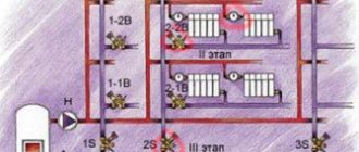
An example of calculations. The conditions in this case are as follows: an administrative building has three floors.
Stage one
This includes the aerodynamic calculation of mechanical air conditioning or ventilation systems, which includes a number of sequential operations. A perspective diagram is drawn up, which includes ventilation: both supply and exhaust, and is prepared for the calculation.
The dimensions of the cross-sectional area of the air ducts are determined depending on their type: round or rectangular.
Formation of the scheme
The diagram is drawn up in perspective with a scale of 1: 100. It indicates the points with the located ventilation devices and the consumption of air passing through them.
Here you should decide on the trunk - the main line on the basis of which all operations are carried out. It is a chain of sections connected in series, with the greatest load and maximum length.
When building a highway, you should pay attention to which system is being designed: supply or exhaust.
Supply
Here, the billing line is built from the most distant air distributor with the highest consumption. It passes through supply elements such as air ducts and air handling units up to the point where air is drawn in. If the system is to serve several floors, then the air distributor is located on the last one.
Exhaust
A line is being built from the most remote exhaust device, which maximizes the consumption of air flow, through the main line to the installation of the hood and further to the shaft through which air is released.
If ventilation is planned for several levels and the installation of the hood is located on the roof or attic, then the calculation line should start from the air distribution device of the lowest floor or basement, which is also included in the system. If the hood is installed in the basement, then from the air distribution device of the last floor.
The entire calculation line is divided into segments, each of them is a section of the duct with the following characteristics:
- duct of uniform cross-sectional size;
- from one material;
- with constant air consumption.
The next step is numbering the segments. It starts with the most distant exhaust device or air distributor, each assigned a separate number. The main direction - the highway is highlighted with a bold line.
Further, on the basis of an axonometric diagram for each segment, its length is determined, taking into account the scale and air consumption. The latter is the sum of all the values of the consumed air flow flowing through the branches that are adjacent to the line. The value of the indicator, which is obtained as a result of sequential summation, should gradually increase.
Determination of dimensional values of air duct cross-sections
Produced on the basis of indicators such as:
- air consumption in the segment;
- the normative recommended values of the air flow speed are: on highways - 6m / s, in mines where air is taken - 5m / s.
The preliminary dimensional value of the duct on the segment is calculated, which is brought to the nearest standard. If a rectangular duct is selected, then the values are selected based on the dimensions of the sides, the ratio between which is no more than 1 to 3.
Air speed determination rules
Air speed is closely related to concepts such as the noise level and vibration level in the ventilation system. The air passing through the ducts creates a certain amount of noise and pressure, which increases with the number of turns and bends.
The higher the resistance in the pipes, the lower the air speed and the higher the fan performance. Consider the norms of associated factors.
No. 1 - sanitary norms of noise level
The standards specified in SNiP relate to residential premises (private and apartment buildings), public and industrial types.
In the table below, you can compare the norms for different types of premises, as well as areas adjacent to buildings.
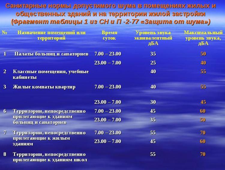
Part of the table from No. 1 SNiP-2-77 from the paragraph "Protection against noise". The maximum allowable norms related to night time are lower than daytime values, and the norms for adjacent territories are higher than for residential premises
One of the reasons for the increase in accepted standards may just be an incorrectly designed air duct system.
Sound pressure levels are shown in another table:
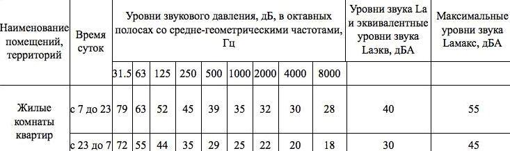
When commissioning ventilation or other equipment associated with ensuring a favorable, healthy microclimate in the room, only a short-term excess of the indicated noise parameters is allowed
No. 2 - vibration level
The fan power is directly related to the vibration level.
The maximum vibration threshold depends on several factors:
- the size of the duct;
- the quality of the gaskets to reduce the vibration level;
- pipe material;
- the speed of the air flow passing through the channels.
The norms that should be followed when choosing ventilation devices and when calculating air ducts are presented in the following table:
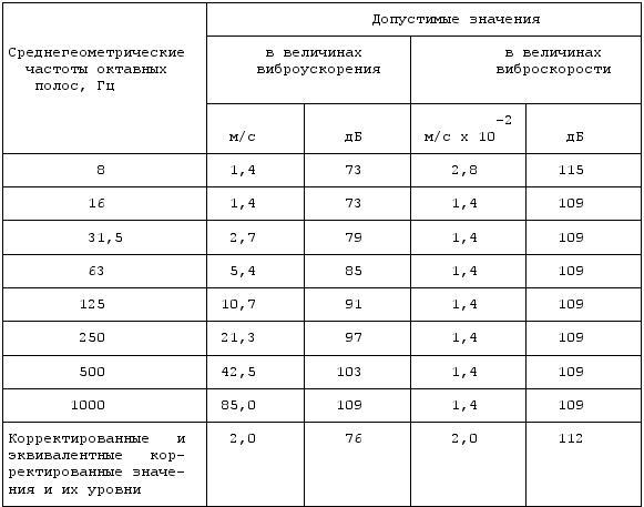
Maximum permissible values of local vibration. If, during the check, the actual values are higher than the norms, it means that the duct system is designed with technical flaws that need to be corrected, or the fan power is too high.
The air speed in mines and channels should not affect the increase in vibration indicators, as well as the associated parameters of sound vibrations.
No. 3 - the frequency of air exchange
Air purification occurs due to the air exchange process, which is subdivided into natural or forced.
In the first case, it is carried out by opening doors, transoms, vents, windows (and called aeration) or simply by infiltration through cracks at the joints of walls, doors and windows, in the second - using air conditioners and ventilation equipment.
Air changes in a room, utility room or workshop should be performed several times per hour so that the degree of contamination of the air masses is acceptable. The number of shifts is a multiplicity, a value that is also necessary to determine the air speed in the ventilation ducts.
The multiplicity is calculated using the following formula:
N = V / W,
Where:
- N - the frequency of air exchange, once every 1 hour;
- V - volume of clean air filling the room for 1 hour, m³ / h;
- W - the volume of the room, m³.
In order not to perform additional calculations, the average multiplicity indicators are collected in tables.
For example, the following air exchange rate table is suitable for residential premises:
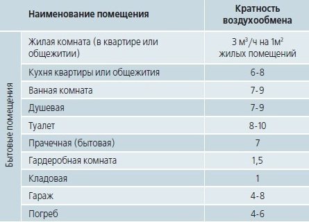
Judging by the table, a frequent change of air masses in a room is necessary if it is characterized by high humidity or air temperature - for example, in a kitchen or a bathroom. Accordingly, with insufficient natural ventilation in these rooms, forced circulation devices are installed.
What happens if the air exchange rate standards are not met or are, but not enough?
One of two things will happen:
- The multiplicity is below the norm. Fresh air stops replacing polluted air, as a result of which the concentration of harmful substances in the room increases: bacteria, pathogens, hazardous gases. The amount of oxygen, which is important for the human respiratory system, decreases, while carbon dioxide, on the contrary, increases. Humidity rises to a maximum, which is fraught with mold.
- The multiplicity is higher than the norm. It occurs if the speed of air movement in the channels exceeds the norm.This negatively affects the temperature regime: the room simply does not have time to heat up. Excessively dry air provokes skin and respiratory diseases.
In order for the frequency of air exchange to comply with sanitary standards, it is necessary to install, remove or adjust ventilation devices, and, if necessary, replace the air ducts.
Stage two
The aerodynamic drag figures are calculated here. After choosing the standard cross-sections of the air ducts, the value of the air flow rate in the system is specified.
Calculation of friction pressure loss
The next step is to determine the specific friction pressure loss based on tabular data or nomograms. In some cases, a calculator can be useful to determine indicators based on a formula that allows you to calculate with an error of 0.5 percent. To calculate the total value of the indicator characterizing the pressure loss over the entire section, you need to multiply its specific indicator by the length. At this stage, the roughness correction factor should also be taken into account. It depends on the magnitude of the absolute roughness of a particular duct material, as well as the speed.
Calculating the dynamic pressure indicator on a segment
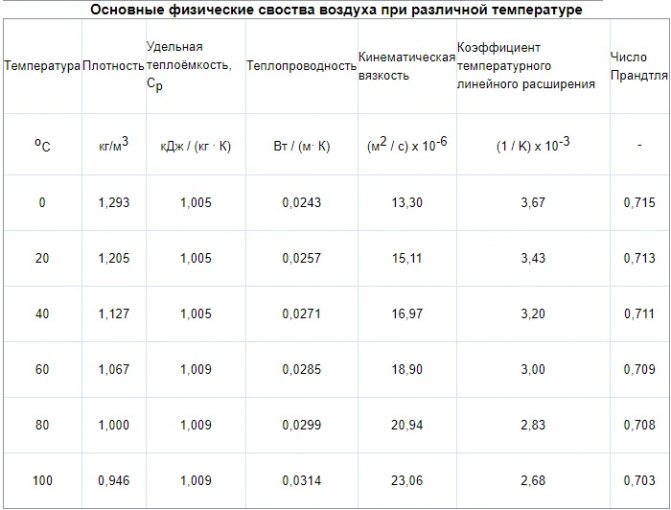
Here, an indicator is determined that characterizes the dynamic pressure in each section based on the values:
- air flow rate in the system;
- the density of the air mass under standard conditions, which is 1.2 kg / m3.
Determination of the values of local resistances in the sections
They can be calculated based on the local resistance coefficients. The obtained values are summarized in a tabular form, which includes the data of all sections, and not only straight segments, but also several fittings. The name of each element is entered in the table, the corresponding values and characteristics are also indicated there, according to which the coefficient of local resistance is determined. These indicators can be found in the relevant reference materials for the selection of equipment for ventilation units.
In the presence of a large number of elements in the system or in the absence of certain values of the coefficients, a program is used that allows you to quickly carry out cumbersome operations and optimize the calculation as a whole. The total resistance value is determined as the sum of the coefficients of all elements of the segment.
Calculation of pressure losses on local resistances
Having calculated the final total value of the indicator, they proceed to calculating the pressure losses in the analyzed areas. After calculating all segments of the main line, the obtained numbers are summed up and the total value of the resistance of the ventilation system is determined.
Features of aerodynamic calculations
Let's get acquainted with the general method for carrying out this kind of calculations, provided that both the cross section and the pressure are unknown to us. Let's make a reservation right away that the aerodynamic calculation should be carried out only after the required volumes of air masses have been determined (they will pass through the air conditioning system) and the approximate location of each of the air ducts in the network has been designed.
And in order to carry out the calculation, it is necessary to draw an axonometric diagram, in which there will be a list of all the elements of the network, as well as their exact dimensions. In accordance with the plan of the ventilation system, the total length of the air ducts is calculated. After that, the entire system should be divided into segments with homogeneous characteristics, according to which (only individually!) The air consumption will be determined. Typically, for each of the homogeneous sections of the system, a separate aerodynamic calculation of the air ducts should be carried out, because each of them has its own speed of movement of air flows, as well as a permanent flow rate. All the obtained indicators must be entered into the axonometric diagram already mentioned above, and then, as you probably already guessed, you must select the main highway.
Stage three: linking branches
When all the necessary calculations have been carried out, it is necessary to link several branches. If the system serves one level, then the branches that are not included in the trunk are connected. The calculation is carried out in the same manner as for the main line. The results are recorded in a table. In multi-storey buildings, floor branches at intermediate levels are used for linking.
Linkage criteria
Here, the values of the sum of losses are compared: pressure along the sections to be linked with a parallel-connected line. It is necessary that the deviation is no more than 10 percent. If it is found that the discrepancy is greater, then the linking can be carried out:
- by selecting the appropriate dimensions for the cross-section of the ducts;
- by installing on branches of diaphragms or butterfly valves.
Sometimes, to carry out such calculations, you just need a calculator and a couple of reference books. If it is required to carry out an aerodynamic calculation of the ventilation of large buildings or industrial premises, then an appropriate program will be needed. It will allow you to quickly determine the dimensions of the sections, pressure losses both in individual sections and in the entire system as a whole.
https://www.youtube.com/watch?v=v6stIpWGDow Video can’t be loaded: Ventilation system design. (https://www.youtube.com/watch?v=v6stIpWGDow)
The purpose of the aerodynamic calculation is to determine the pressure loss (resistance) to air movement in all elements of the ventilation system - air ducts, their shaped elements, grilles, diffusers, air heaters and others. Knowing the total value of these losses, it is possible to select a fan capable of providing the required air flow. Distinguish between direct and inverse problems of aerodynamic calculation. The direct problem is solved in the design of newly created ventilation systems, consists in determining the cross-sectional area of all sections of the system at a given flow rate through them. The inverse problem is to determine the air flow rate for a given cross-sectional area of the operated or reconstructed ventilation systems. In such cases, to achieve the required flow rate, it is sufficient to change the fan speed or replace it with a different standard size.
The aerodynamic calculation begins after determining the rate of air exchange in the premises and making a decision on the routing (laying scheme) of air ducts and channels. The air exchange rate is a quantitative characteristic of the operation of the ventilation system, it shows how many times within 1 hour the volume of air in the room will be completely replaced with a new one. The multiplicity depends on the characteristics of the room, its purpose and may differ several times. Before starting the aerodynamic calculation, a system diagram is created in an axonometric projection and a scale of M 1: 100. The main elements of the system are distinguished on the diagram: air ducts, their fittings, filters, silencers, valves, air heaters, fans, grilles and others. According to this scheme, the building plans of the premises determine the length of the individual branches. The circuit is divided into calculated sections, which have a constant air flow. The boundaries of the calculated sections are shaped elements - bends, tees and others. Determine the flow rate in each section, apply it, length, section number on the diagram. Next, a trunk is selected - the longest chain of successively located sections, counting from the beginning of the system to the most distant branch. If there are several lines of the same length in the system, then the main one is chosen with a high flow rate. The shape of the cross-section of the air ducts is taken - round, rectangular or square. The pressure losses in the sections depend on the air speed and consist of: friction losses and local resistances. The total pressure loss of the ventilation system is equal to the line loss and consists of the sum of the losses of all its calculated sections. The direction of calculation is chosen - from the farthest section to the fan.
By area F
determine the diameter
D
(for round shape) or height
A
and width
B
(for rectangular) duct, m.The values obtained are rounded to the nearest larger standard size, i.e.
D st
,
A st
and
In st
(reference value).
Recalculate the actual cross-sectional area F
fact and speed
v fact
.
For a rectangular duct, determine the so-called. equivalent diameter DL = (2A st * B st) / (A
st+ Bst), m.
Determine the value of the Reynolds similarity criterion Re = 64100 * D
st* v fact.
For rectangular shape
D L = D Art.
Friction coefficient λ tr = 0.3164 ⁄ Re-0.25 at Re≤60000, λ
tr= 0.1266 ⁄ Re-0.167 at Re> 60,000.
Local resistance coefficient λm
depends on their type, quantity and is selected from reference books.
Comments:
- Initial data for calculations
- Where to start? Calculation order
The heart of any ventilation system with mechanical airflow is the fan, which creates this flow in the ducts. The power of the fan directly depends on the pressure that must be created at the outlet from it, and in order to determine the magnitude of this pressure, it is required to calculate the resistance of the entire system of channels.
To calculate the pressure loss, you need the layout and dimensions of the duct and additional equipment.
E.1 Aerodynamic coefficients
E.1.1 Freestanding flat solid structures
Freestanding
flatsolidconstructionson theearth
(
walls
,
fencesandt
.
d
.)
For various sections of structures (Figure E.1), the coefficient cx
determined according to table E.1;
ze
=
h
.
Figure E.1
Table E.1
| Areas of flat solid structures on the ground (see figure D.1 ) | |||
| BUT | AT | WITH | D |
| 2,1 | 1,8 | 1,4 | 1,2 |
Advertising
shields
For billboards raised above the ground to a height of at least d
/ 4 (figure
D 2
):
cx
= 2,5
k
l, where
k
l - defined in
D.1.15
.
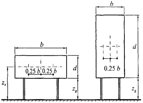
Figure E.2
The resultant load normal to the plane of the shield should be applied at the height of its geometric center with eccentricity in the horizontal direction e
= ± 0,25
b
.
ze
=
zg
+
d
/2.
E.1.2 Rectangular buildings with gable roofs
Vertical
wallsrectangularatplanbuildings
Table E.2
| Side walls | Windward wall | Leeward wall | ||
| Plots | ||||
| BUT | AT | WITH | D | E |
| -1,0 | -0,8 | -0,5 | 0,8 | -0,5 |
For upwind, leeward and various sidewall sections (picture D.3
) aerodynamic coefficients
behold
are given in the table
D 2
.
For side walls with protruding loggias, the aerodynamic coefficient of friction withf
= 0,1.
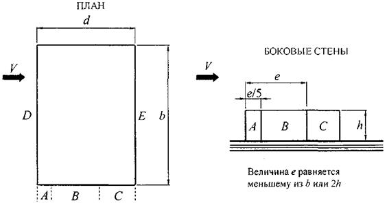
Figure E.3
Gable
coverings
For different areas of coverage (figure D.4
) coefficient
behold
determined by tables
D.3
and and
D.3
, b depending on the direction of the average wind speed.
For angles 15 ° £ b £ 30 ° at a = 0 °, it is necessary to consider two variants of the distribution design wind load
.
For extended smooth coatings at a = 90 ° (figure D.4
, b) aerodynamic coefficients of friction
withf
= 0,02.
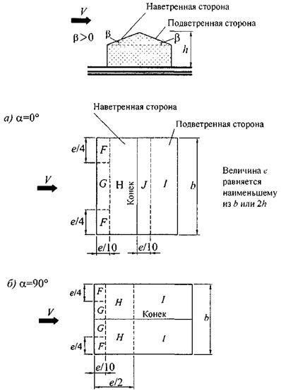
Figure E.4
Table E.3a
- a
| Slope b | F | G | H | I | J |
| 15° | -0,9 | -0,8 | -0,3 | -0,4 | -1,0 |
| 0,2 | 0,2 | 0,2 | |||
| 30° | -0,5 | -0,5 | -0,2 | -0,4 | -0,5 |
| 0,7 | 0,7 | 0,4 | |||
| 45° | 0,7 | 0,7 | 0,6 | -0,2 | -0,3 |
| 60° | 0,7 | 0,7 | 0,7 | -0,2 | -0,3 |
| 75° | 0,8 | 0,8 | 0,8 | -0,2 | -0,3 |
Table E.3b
- a
| Slope b | F | WITH | H | I |
| 0° | -1,8 | -1,3 | -0,7 | -0,5 |
| 15° | -1,3 | -1,3 | -0,6 | -0,5 |
| 30° | -1,1 | -1,4 | -0,8 | -0,5 |
| 45° | -1,1 | -1,4 | -0,9 | -0,5 |
| 60° | -1,1 | -1,2 | -0,8 | -0,5 |
| 75° | -1,1 | -1,2 | -0,8 | -0,5 |
E.1.3 Rectangular buildings in the plan with vaulted and close to them in outline coverings
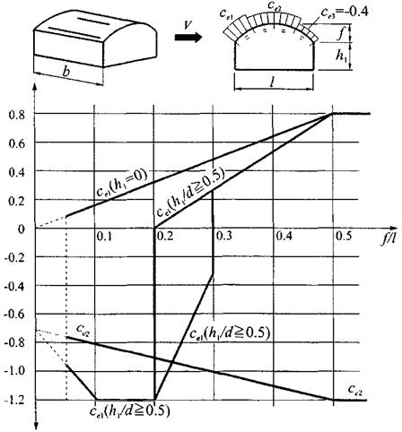
Figure E.5
Note
- At £ 0.2
f
/
d
£ 0.3 and
hl
/
l
³ 0.5, two values of the coefficient must be taken into account
behold
1.
The distribution of aerodynamic coefficients over the surface of the coating is shown in the figure D.5
.
Aerodynamic coefficients for walls are taken in accordance with the table D 2
.
When determining the equivalent height (11.1.5
) and coefficient
v
in accordance with
11.1.1
:
h
=
h
1 + 0,7
f
.
E.1.4 Round-shaped buildings with domed roofs
Coefficient values behold
in points
BUT
and
WITH
,
but
also in the explosive section are shown in the figure
D.6
... For intermediate sections, the coefficients
behold
determined by linear interpolation.
When determining the equivalent height (11.1.5
) and coefficient
v
in accordance with
11.1.1
:
h
=
h
1 + 0,7
f
.
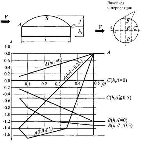
Figure E.6
E.1.5 Buildings with longitudinal lights
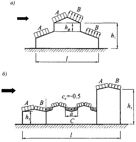
Figure E.7
For sections A and B (Figure E.7) the coefficients behold
should be determined in accordance with the tables
D.3
,
but
and
D.3
,
b
.
For site lanterns WITH
for l £ 2
cx
= 0.2; for 2 £ l £ 8 for each lamp
cx
= 0.1l; at l
>
8
cx
= 0.8, here l =
a
/
hf
.
For other areas of coverage behold
= -0,5.
For vertical surfaces and walls of buildings, the coefficients behold
should be determined in accordance with the table
D 2
.
When determining the equivalent height zе
(
11.1.5
) and coefficient
v
(
11.1.1
)
h
=
h
1.
E.1.6 Buildings with skylights
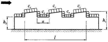
Figure E.8
For a windward lantern, the coefficient behold
should be determined in accordance with the tables
D.3
,
but
and
D.3
,
b
.
For the rest of the lights, the coefficients cx
are defined in the same way as for the site
WITH
(section
D.1.5
).
For the rest of the coverage behold
= -0,5.
For vertical surfaces and walls of buildings, the coefficients behold
should be determined in accordance with the table
D 2
.
When determining the equivalent height ze
(
11.1.5
) and coefficient
v
(
11.1.1
)
h
=
h
1.
E.1.7 Buildings with shaded coatings
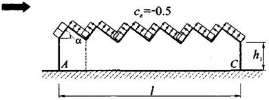
Figure E.9
For section A, the coefficient behold
should be determined in accordance with the tables
D.3
,
but
and
D.3
,
b
.
For the rest of the coverage behold
= -0,5.
For vertical surfaces and walls of buildings, the coefficients behold
should be determined in accordance with the table
D 2
.
When determining the equivalent height ze
(
11.1.5
) and coefficient
v
(
11.1.1
)
h
=
h
1.
E.1.8 Buildings with ledges
Figure E.10
For the plot WITH
coefficient
behold
= 0,8.
For the plot BUT
coefficient
behold
should be taken in accordance with the table
D 2
.
For the plot AT
coefficient
behold
should be determined by linear interpolation.
For other vertical surfaces, the coefficient behold
must be determined in accordance with the table
D 2
.
To cover buildings, the coefficients behold
determined according to tables
D.3
,
but
and
D.3
,
b
.
E.1.9 Buildings permanently open on one side
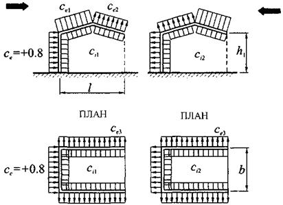
Figure E.11
With the permeability of the fence m £ 5% withi
1 =
ci
2 = ± 0.2. For each wall of the building, the "plus" or "minus" sign should be selected from the conditions for the implementation of the most unfavorable loading option.
For m ≥ 30% withi
1 = -0,5;
ci
2 = 0,8.
Coefficient behold
on the outer surface should be taken in accordance with the table
D 2
.
Note
- The permeability of the fence m should be determined as the ratio of the total area of the openings in it to the total area of the fence.
E.1.10 Sheds
Aerodynamic coefficients behold
for four types of awnings (picture
D.12
) without continuous vertical enclosing structures are determined according to the table
D.4
.
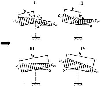
Figure E.12
Table E.4
| Scheme type | a, deg | Coefficient values | |||
| ce 1 | ce 2 | ce 3 | ce 4 | ||
| I | 10 | 0,5 | -1,3 | -1,1 | 0 |
| 20 | 1,1 | 0 | 0 | -0,4 | |
| 30 | 2,1 | 0,9 | 0,6 | 0 | |
| II | 10 | 0 | -1,1 | -1,5 | 0 |
| 20 | 1,5 | 0,5 | 0 | 0 | |
| 30 | 2 | 0,8 | 0,4 | 0,4 | |
| III | 10 | 1,4 | 0,4 | — | — |
| 20 | 1,8 | 0,5 | — | — | |
| 30 | 2,2 | 0,6 | — | — | |
| IV | 10 | 1,3 | 0,2 | — | — |
| 20 | 1,4 | 0,3 | — | — | |
| 30 | 1,6 | 0,4 | — | — | |
| Notes 1 Odds behold 1, 2 For negative values behold 1, 3 For canopies with corrugated surfaces, the aerodynamic coefficient of friction cf = 0,04. | |||||
D.1.11 Sphere
Figure E.13
Aerodynamic drag coefficients cx
spheres at
zg>d
/ 2 (figure
D.13
) are shown in the figure
D.14
depending on the Reynolds number
Re
and relative roughness d = D /
d
, where D, m, is the surface roughness (see.
D.1.15
). When
zg<d
/ 2 ratio
cx
should be increased by 1.6 times.
Lift coefficient of the sphere cz
is taken equal to:
at zg
>
d
/2 —
cz
= 0;
at zg
<d
/2 —
withz
= 0,6.
Typo
Equivalent height (11.1.5
)
ze
=
zg
+
d
/2.
When determining the coefficient v
in accordance with
11.1.11
should be taken
b
=
h
= 0,7
d
.
Reynolds number Re
is determined by the formula
Where d
, m, is the diameter of the sphere;
w
0, Pa, - is determined in accordance with
11.1.4
;
ze
, m, - equivalent height;
k
(
ze
) - is determined in accordance with
11.1.6
;
- gf
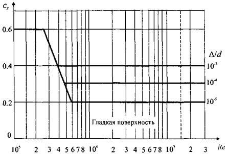
Figure E.14
E.1.12 Structures and structural elements with a circular cylindrical surface
Aerodynamic coefficient ce1
external pressure is determined by the formula
ce
1 =
k
l1
c
b,
Where k
l1 = 1 for
with
b> 0; for
with
b <0 -
k
l1 =
k
l, defined in
D.1.15
.
Distribution of cb coefficients over the cylinder surface at d = D /d
<
5 × 10⁻⁴ (see.
D.1.16
) is shown in the figure
D.16
for different Reynolds numbers
Re
... The values of the angles bmin and b indicated in this figure
b
, as well as the corresponding value of the coefficients
with
min and
withb
are given in the table
D.5
.
Values of aerodynamic pressure coefficients behold
2 and
withi
(picture
D.14
) are given in the table
D.6
... Coefficient
withi
should be taken into account for a lowered roof (“floating roof”), as well as in the absence of a roof.
Aerodynamic drag coefficients are determined by the formula
cX
=
k
l
cx
¥,
Where k
l - defined in
D.1
depending on the relative elongation of the structure (see.
D.1.15
). Coefficient values
cx
¥ are shown in the picture
D.17
depending on the Reynolds number
Re
and relative roughness D = d /
d
(cm.
D.1.16
).
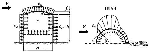
Figure E.15
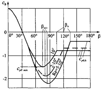
Figure E.16
Table E.5
| Re | bmin | c min | bb | cb |
| 5×10⁵ | 85 | -2,2 | 135 | -0,4 |
| 2×10⁶ | 80 | -1,9 | 120 | -0,7 |
| 107 | 75 | -1,5 | 105 | -0,8 |
Table E.6
| h / d | 1/6 | 1/4 | 1/2 | 1 | 2 | ³ 5 |
| ce 2, | -0,5 | -0,55 | -0,7 | -0,8 | -0,9 | -1,05 |
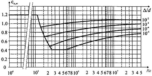
Figure E.17
For wires and cables (including those covered with ice) cx
= 1,2.
Aerodynamic coefficients of inclined elements (figure D.18
) are determined by the formula
cx
b =
cx
sin2bsin2q.
Where cx
- determined in accordance with the data in the figure
D.17
;
axis x
parallel to wind speed
V
;
axis z
directed vertically upwards;
- bXY
and axis
x
; - qz
.
Figure E.18
When determining the coefficient v
in accordance with
11.1.1
:
b
= 0,7
d
;
h
=
h
1 + 0,7
f
.
Reynolds number Re
determined by the formula given in
D.1.11
where
zе
= 0,8
h
for vertically located structures;
ze
is equal to the distance from the surface of the earth to the axis of a horizontally located structure.
E.1.13 Prismatic structures
Typo
The aerodynamic drag coefficients of prismatic structures are determined by the formula
cX
=
k
l
cX
¥,
Where k
l defined in
D.1.15
depending on the relative lengthening of the structure l
e
.
Coefficient values cX
¥ for rectangular sections are shown in the figure
D.19
, and for
n
-gonal sections and structural elements (profiles) - in the table
D 7
.
Table E.7
| Sketches of sections and wind directions | b, deg. | P (number of sides) | cx ¥ at |
| Regular polygon | Arbitrary | 5 | 1,8 |
| 6 — 8 | 1,5 | ||
| 10 | 1,2 | ||
| 12 | 1,0 |
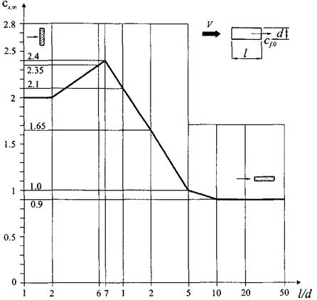
Figure E.19
E.1.14 Lattice structures
The aerodynamic coefficients of lattice structures are related to the area of the edges of spatial trusses or the area of the contour of flat trusses.
Axis direction x
for flat trusses, coincides with the direction of the wind and is perpendicular to the plane of the structure; for spatial trusses, the calculated wind directions are shown in the table
D.8
.
Aerodynamic
oddscxdetachedflatlatticeconstructionsare determinedbyformula
Where cxi
- aerodynamic coefficient
i
-th structural element, determined in accordance with the instructions
D.1.13
for profiles and
D.1.12
, in for tubular elements; wherein
k
l = 1;
Ai
- projection area
i
th structural element;
Ak
- the area limited by the contour of the structure.
Figure E.20
Row
flatparallellocatedlatticeconstructions
Figure E.21
For a windward structure, the coefficient cxl
is defined in the same way as for a free-standing farm.
For the second and subsequent designs cx
2 =
cx
1h.
For trusses made of pipe profiles with Re
<4 × 10⁵ coefficient h is determined from the table
D.8
depending on the relative distance between the trusses
b
/
h
(picture
D.19
) and the permeability coefficient of the trusses
Table E.8
| j | b / | ||||
| 1/2 | 1 | 2 | 4 | 6 | |
| 0,1 | 0,93 | 0,99 | 1 | 1 | 1 |
| 0,2 | 0,75 | 0,81 | 0,87 | 0,9 | 0,93 |
| 0,3 | 0,56 | 0,65 | 0,73 | 0,78 | 0,83 |
| 0,4 | 0,38 | 0,48 | 0,59 | 0,65 | 0,72 |
| 0,5 | 0,19 | 0,32 | 0,44 | 0,52 | 0,61 |
| 0,6 | 0 | 0,15 | 0,3 | 0,4 | 0,5 |
For pipe trusses at Re
³ 4 × 10⁵ h = 0.95.
Note
- Reynolds number
Re
should be determined by the formula in subsection
D.1.11
where
d
Is the average diameter of the tubular elements.
Lattice
towersandspatialfarms
Figure E.22
Aerodynamic coefficients withl
lattice towers and space trusses are determined by the formula
cl
=
cx
(1 + h)
k
1,
Where cx
- is determined in the same way as for a free-standing farm;
- h
Coefficient values k
1 are given in the table
D.9
.
Table E.9
| Cross-sectional shape and wind direction | k 1 |
| 1 | |
| 0,9 | |
| 1,2 |
E.1.15 Taking into account the relative elongation
Coefficient values k
l depending on the relative elongation l
e
element or structure are shown in the figure
D.23
... Elongation l
e
depends on the parameter l =
l
/
b
and is determined by the table
D.10
; permeability
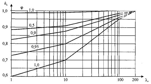
Figure E.23
Table E.10
| ||
| Note — | ||
E.1.16 Taking into account the roughness of the outer surface
The values of the coefficient D characterizing the roughness of the surfaces of structures, depending on their processing and the material from which they are made, are given in the table D.11
.
Table E.11
| Surface type | Relative roughness d, mm | Surface type | Relative roughness d, mm |
| Glass | 0,0015 | Cink Steel | 0,2 |
| Polished metal | 0,002 | Sanded concrete | 0,2 |
| Finely ground oil paint | 0,006 | Rough concrete | 1,0 |
| Spray paint | 0,02 | Rust | 2,0 |
| Cast iron | 0,2 | Masonry | 3,0 |
D.1.17 Peak values of aerodynamic coefficients for rectangular buildings
a) For walls of rectangular buildings, the peak positive value of the aerodynamic coefficient Wed
,
+
= 1,2.
b) Peak values of negative aerodynamic coefficient Wed
,
—
for walls and flat coverings (picture
D.24
) are given in the table
D.12
.
Table E.12
| Plot | BUT | AT | WITH | D | E |
| cp ,- | -2,2 | -1,2 | -3,4 | -2,4 | -1,5 |
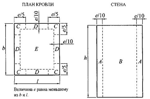
Figure E.24
E.2 Resonant vortex excitation
E.2.1 For single-span structures and structural elements, the intensity of exposure F
(
z
) acting under resonant vortex excitation along
i
-th proper form in the direction perpendicular to the average wind speed is determined by the formula
N / m, (D.2.1)
Where d
, m, is the size of the structure or structural element in the direction perpendicular to the average wind speed;
Vcr
,
i
, m / s, - see.
11.3.2
;
cy
,
cr
- aerodynamic coefficient of transverse force at resonant vortex excitation;
- d
- dd
z
- coordinate that changes along the axis of the structure;
ji
(
z
) —
i
-th form of natural vibrations in the transverse direction, satisfying the condition
max [j (z
)] = 1. (D.2.2)
Note
- The impact at resonant vortex excitation (primarily high-rise buildings) is recommended to be clarified on the basis of model aerodynamic test data.
E.2.2 Aerodynamic coefficients su
lateral forces are defined as follows:
a) For round cross-sections su
= 0,3.
b) For rectangular cross-sections at b
/
d
> 0,5:
cy
= 1.1 for
Vcr
,
i
/
V
max (
z
eq) <0.8;
su
= 0.6 for
Vcr
,
i
/
V
max (
z
eq) ³ 0.8,
here b
- the size of the structure in the direction of the average wind speed.
When b
/
d
£ 0.5 calculation for resonant vortex excitation is allowed not to be carried out.
E.2.3 When calculating a structure for resonant vortex excitation, along with the effect (D.2.1
) it is also necessary to take into account the effect of a wind load parallel to the average wind speed. Average
wm
,
cr
and pulsating
wp
,
cr
the components of this impact are determined by the formulas:
wm
,
cr
= (
Vcr
/
V
max) 2
wm
;
wp
,
cr
= (
Vcr
/
V
max) 2
wp
, (D.2.3)
Where V
max - estimated wind speed at altitude
z
eq, on which the resonant vortex excitation occurs, determined by the formula (
11.13
);
wm
and
wp
- the calculated values of the average and pulsation components of the wind load, determined in accordance with the instructions
11.1
.
E.2.4 Critical speeds Vcr
,
i
can have a sufficiently large repeatability during the design life of the structure and, therefore, resonant vortex excitation can lead to the accumulation of fatigue damage.
To prevent resonant vortex excitation, various constructive measures can be used: installation of vertical and spiral ribs, perforation of the fence and installation of appropriately tuned vibration dampers.
Source: stroyinf.ru
Initial data for calculations
When the diagram of the ventilation system is known, the dimensions of all air ducts are selected and additional equipment is determined, the diagram is depicted in a frontal isometric projection, that is, a perspective view. If it is carried out in accordance with the current standards, then all the information necessary for the calculation will be visible on the drawings (or sketches).
- With the help of floor plans, you can determine the lengths of the horizontal sections of air ducts. If, on the axonometric diagram, the elevation marks are put on which the channels pass, then the length of the horizontal sections will also become known. Otherwise, sections of the building with laid routes of air ducts will be required. And as a last resort, when there is not enough information, these lengths will have to be determined using measurements at the installation site.
- The diagram should show with the help of symbols all additional equipment installed in the channels.These can be diaphragms, motorized dampers, fire dampers, as well as devices for distributing or exhausting air (grilles, panels, umbrellas, diffusers). Each piece of this equipment creates resistance in the air flow path, which must be taken into account when calculating.
- In accordance with the standards on the diagram, air flow rates and channel sizes should be indicated next to the conventional images of the air ducts. These are the defining parameters for calculations.
- All shaped and branching elements should also be reflected in the diagram.
If such a diagram does not exist on paper or in electronic form, then you will have to draw it at least in a rough version; you cannot do without it when calculating.
Back to the table of contents
Recommended rates of air exchange rate
During the design of the building, the calculation of each individual section is performed. In production, these are workshops, in residential buildings - apartments, in a private house - floor blocks or separate rooms.
Before installing the ventilation system, it is known what the routes and dimensions of the main highways are, what geometry ventilation ducts are needed, what pipe size is optimal.
Do not be surprised by the overall dimensions of the air ducts in catering establishments or other institutions - they are designed to remove a large amount of used air
Calculations related to the movement of air flows inside residential and industrial buildings are classified as the most complex, therefore, experienced qualified specialists are required to deal with them.
The recommended air speed in the ducts is indicated in SNiP - regulatory state documentation, and when designing or commissioning objects, they are guided by it.
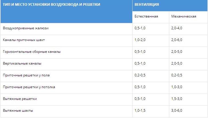
The table shows the parameters that should be adhered to when installing a ventilation system. The numbers indicate the speed of movement of air masses in the places of installation of channels and gratings in generally accepted units - m / s
It is believed that indoor air speed should not exceed 0.3 m / s.
Exceptions are temporary technical circumstances (for example, repair work, installation of construction equipment, etc.), during which the parameters can exceed the standards by a maximum of 30%.
In large rooms (garages, production halls, warehouses, hangars), instead of one ventilation system, two often operate.
The load is divided in half, therefore, the air speed is selected so that it provides 50% of the total estimated volume of air movement (removal of contaminated or supply of clean air).
In the event of force majeure circumstances, it becomes necessary to abruptly change the air speed or to completely stop the operation of the ventilation system.
For example, according to fire safety requirements, the speed of air movement is reduced to a minimum in order to prevent the spread of fire and smoke in adjacent rooms during a fire.
For this purpose, cut-off devices and valves are mounted in the air ducts and in the transition sections.
Where to start?
Diagram of head loss per meter of duct.
Very often you have to deal with fairly simple ventilation schemes, in which there is an air duct of the same diameter and there is no additional equipment. Such circuits are calculated quite simply, but what if the circuit is complex with many branches? According to the method for calculating pressure losses in air ducts, which is described in many reference publications, it is necessary to determine the longest branch of the system or the branch with the greatest resistance. It is rarely possible to find out such resistance by eye, therefore it is customary to calculate along the longest branch. After that, using the air flow rates indicated on the diagram, the entire branch is divided into sections according to this feature.As a rule, the costs change after branching (tees) and when dividing it is best to focus on them. There are other options, for example, supply or exhaust grilles built directly into the main duct. If this is not shown on the diagram, but there is such a lattice, it will be necessary to calculate the flow rate after it. Sections are numbered starting from the farthest from the fan.
Back to the table of contents
The importance of air exchange for humans
According to construction and hygiene standards, each residential or industrial facility must be provided with a ventilation system.
Its main purpose is to maintain air balance, create a microclimate favorable for work and rest. This means that in the atmosphere that people breathe, there should not be an excess of heat, moisture, and various kinds of pollution.
Violations in the organization of the ventilation system lead to the development of infectious diseases and diseases of the respiratory system, to a decrease in immunity, to premature spoilage of food.
In an excessively humid and warm environment, pathogens develop rapidly, and foci of mold and mildew appear on walls, ceilings and even furniture.
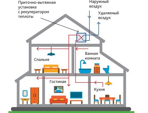
Ventilation scheme in a two-story private house. The ventilation system is equipped with a supply and exhaust energy-saving unit with a heat recuperator, which allows you to reuse the heat of the air removed from the building
One of the prerequisites for maintaining a healthy air balance is proper ventilation system design. Each part of the air exchange network must be selected based on the volume of the room and the characteristics of the air in it.
Suppose that in a small apartment there is a fairly well-established supply and exhaust ventilation, while in production workshops it is mandatory to install equipment for forced air exchange.
When building houses, public institutions, workshops of enterprises, they are guided by the following principles:
- each room must be provided with a ventilation system;
- it is necessary to observe the hygienic parameters of the air;
- enterprises should install devices that increase and regulate the rate of air exchange; in residential premises - air conditioners or fans, provided that there is insufficient ventilation;
- in rooms for different purposes (for example, in wards for patients and an operating room or in an office and in a smoking room), it is necessary to equip different systems.
In order for ventilation to meet the listed conditions, it is necessary to make calculations and select equipment - air supply devices and air ducts.
Also, when installing a ventilation system, it is necessary to choose the right places for air intake in order to prevent contaminated flows from returning to the premises.
In the process of drawing up a ventilation project for a private house, multi-storey residential building or industrial premises, the air volume is calculated and the places for the installation of ventilation equipment are outlined: water exchange units, air conditioners and air ducts
The efficiency of air exchange depends on the size of air ducts (including house mines). Let us find out what are the norms of the air flow rate in ventilation specified in the sanitary documentation.
Image gallery
Photo from
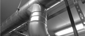
Ventilation system in the attic of the house
Supply and exhaust ventilation equipment
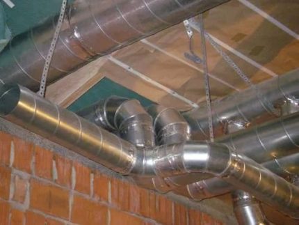
Rectangular plastic air ducts
Local resistances of air ducts