What else is taken into account when calculating the gas pipeline
As a result of friction against the walls, the gas velocity over the pipe section differs - it is faster in the center. However, the average indicator is used for calculations - one conditional speed.
There are two types of movement through pipes: laminar (jet, typical for pipes with a small diameter) and turbulent (it has a disordered nature of movement with involuntary formation of vortices anywhere in a wide pipe).
Calculation of the diameter of the main gas supply pipeline
Gas moves not only because of the external pressure exerted on it. Its layers exert pressure among themselves. Therefore, the hydrostatic head factor is also taken into account.
The movement speed is also influenced by the pipe materials. So in steel pipes during operation, the roughness of the inner walls increases and the axes narrow due to overgrowth. Polyethylene pipes, on the other hand, increase in inner diameter with decreasing wall thickness. All this is taken into account at the design pressure.
Two-pipe home heating system calculation features, diagrams and installation
Even in spite of the relatively simple installation process and the relatively small length of the pipeline in the case of one-pipe heating systems, in the market of specialized equipment, two-pipe heating systems still remain in the first positions.
Although a short, but very convincing and informative list of the advantages and benefits of a two-pipe heating system, it justifies the purchase and subsequent use of circuits with a direct and return line.
Therefore, many consumers prefer it to other varieties, turning a blind eye to the fact that the installation of the system is not so easy.
Why do you need an axonometric diagram
An axonometric diagram is a three-dimensional drawing of a heating system. It is simply unrealistic to make a hydraulic calculation of heating without it. The drawing indicates:
- piping;
- places for reducing the diameter of pipes;
- placement of heat exchangers and other equipment;
- places of installation of pipeline fittings;
- battery volume.
Penofol is often used for insulation. Its technical characteristics allow it to be used even at high temperatures, for example, in a steam room.
We wrote about how to properly insulate the roof of the garage in this article.
Their thermal power depends on the size of the batteries, which should be enough to heat each room. To choose radiators, you need to know the heat loss. The larger they are, the more powerful heat exchangers are needed. Axonometry is performed with respect to scale.
How to work in EXCEL
The use of Excel tables is very convenient, since the results of hydraulic calculations are always reduced to tabular form. It is enough to define the sequence of actions and prepare exact formulas.
Input of initial data
A cell is selected and a value is entered. All other information is simply taken into account.
- the D15 value is recalculated in liters, so it is easier to perceive the flow rate;
- cell D16 - add formatting according to the condition: "If v does not fall within the range 0.25 ... 1.5 m / s, then the background of the cell is red / the font is white."
For pipelines with a difference in inlet and outlet heights, static pressure is added to the results: 1 kg / cm2 per 10 m.
Presentation of results
The author's color scheme carries a functional load:
- Light turquoise cells contain raw data - you can change it.
- Pale green cells - constants to be entered or data that are little subject to change.
- Yellow cells - auxiliary preliminary calculations.
- Light yellow cells - calculation results.
- Fonts: blue - initial data;
- black - intermediate / non-main results;
- red - the main and final results of the hydraulic calculation.
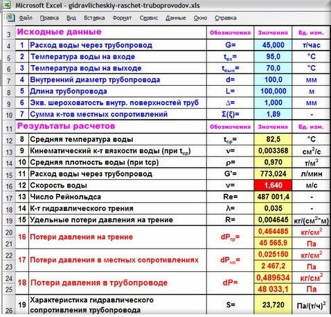
Results in Excel table
Example from Alexander Vorobyov
An example of a simple hydraulic calculation in Excel for a horizontal section of a pipeline.
- pipe length 100 meters;
- ø108 mm;
- wall thickness 4 mm.

Local resistance calculation results table
By complicating step-by-step calculations in Excel, you better master the theory and partially save on design work. Thanks to a competent approach, your heating system will become optimal in terms of costs and heat transfer.
Nomograms for hydraulic pipe calculations
To check the pressure loss in a given area, the manometer readings are compared with tabular data, or they are guided by the functional dependence of the fluid flow rate on voltage changes (with a constant diameter).
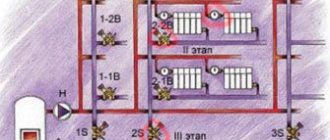
For example, a branch with 10 kW radiators is used. The liquid consumption is calculated for the transfer of heat energy at the level of 10 kW. A cut from the first battery in the branch was taken as a calculated section. Its diameter is constant. The second section is located between the 1st and 2nd batteries. In the second section, the consumption of energy consumed is 9 kW with a possible reduction.
The calculation of the hydraulic resistance is carried out before the return and supply pipes, this is facilitated by the formula:
G uch = (3.6 * Q uch) / (c * (t r-t o)),
where Q uch is the level of heat load of the site, (W). Heat load for 1 section is 10 kW;
с - (indicator of specific heat capacity for liquid) constant equal to 4.2 kJ (kg * ° С);
t r is the temperature regime of the hot coolant;
t o - temperature regime of the cold heat carrier.
Hydrocalculations of heating gravitational systems: the speed of transporting the coolant
The minimum speed of the coolant is 0.2-0.26 m / s. With a decrease in the parameter, excess air masses can be released from the liquid, leading to the formation of air locks. This is the reason for the complete or partial rejection of the heating system. The upper threshold of the coolant velocity is 0.6-1.5 m / s. Failure to reach speed to the specified parameters may generate hydraulic noise. In practice, the optimum speed ranges from 0.4 to 0.7 m / s.
For more accurate calculations, the parameters of materials for the manufacture of pipes are used, For example, for steel pipes, the fluid velocity varies in the range of 0.26-0.5 m / s. When using polymer or copper products, an increase in speed up to 0.26-0.7 m / s is allowed.
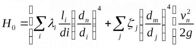
Calculation of the resistance of heating gravity systems: pressure loss
The sum of all losses due to hydraulic friction and local resistance is determined in Pa:
Ruch = R * l + ((p * v2) / 2) * E3,
- where v is the speed of the transported media, m / s;
- p is the density of the liquid, kg / m³;
- R is the pressure loss, Pa / m;
- l is the length used for calculating pipes, m;
- E3 is the sum of all local resistance coefficients in the equipped section of the shut-off valves.
The general level of hydraulic resistance is determined by the sum of the resistances of the calculated sections.
Hydrocalculation of two-pipe gravitational heating systems: selection of the main branch
If the hydraulic system is characterized by the associated transportation of the coolant, for two-pipe systems, you should select the ring of the maximum loaded riser through the heating devices located below. For systems characterized by a dead-end movement of the coolant, it is required to select the ring of the lower heating device for the most loaded from the most distant risers. For horizontal heating structures, rings are selected through the most loaded branches related to the lower floors.
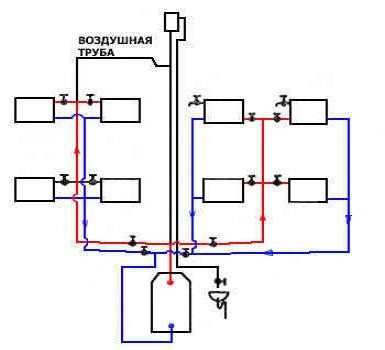
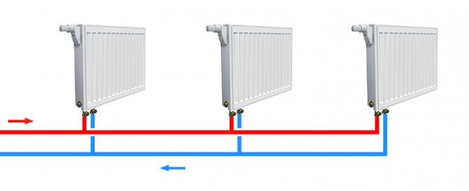
Heating with two lines
A distinctive feature of the structure of the construction of a two-pipe heating system consists of two pipe branches.
The first conducts and directs the water heated in the boiler through all the necessary devices and devices.
The other collects and removes water already cooled during operation and sends it to the heat generator.
In a single-pipe system design, water, in contrast to a two-pipe system, where it is passed through all pipes of heating devices with the same temperature indicator, undergoes a significant loss of characteristics necessary for a stable heating process on the approach to the closing part of the pipeline.
The length of pipes and the costs directly related to it increase doubly when choosing a two-pipe heating system, but this is a relatively insignificant nuance against the background of obvious advantages.
Firstly, for the creation and installation of a two-pipe structure of a heating system, pipes with a large diameter value are not required at all and, therefore, this or that obstacle will not be created in the way, as in the case of a single-pipe circuit.
All the necessary fasteners, valves and other structural details are also much smaller in size, so the difference in cost will be very imperceptible.
One of the main advantages of such a system is that it can be mounted close to each of the thermostat batteries and will significantly reduce costs and increase ease of use.
In addition, the thin ramifications of the supply and return lines also do not interfere with the integrity of the interior of the dwelling at all; moreover, they can simply be hidden behind the cladding or in the wall itself.
Having disassembled all the advantages and nuances of both heating systems on the shelves, the owners, as a rule, still prefer to choose a two-pipe system. However, it is necessary to choose one of several options for such systems, which, in the opinion of the owners themselves, will be the most functional and rational to use.
As in practice, the hydraulic resistance of the heating system is considered.
Engineers often have to calculate heating systems for large facilities. They have a large number of heating devices and many hundreds of meters of pipes, but you still need to count. Indeed, without GH, it will not be possible to choose the right circulation pump. In addition, the GR allows you to determine whether all this will work even before installation.
To simplify life, designers have developed various numerical and software methods for determining hydraulic resistance. Let's start from manual to automatic.
Approximate formulas for calculating hydraulic resistance.
The following approximate formula is used to determine the specific friction losses in the pipeline:
R = 5104 v1.9 / d1.32 Pa / m;
Here, an almost quadratic dependence on the speed of fluid movement in the pipeline remains. This formula is valid for speeds of 0.1-1.25 m / s.
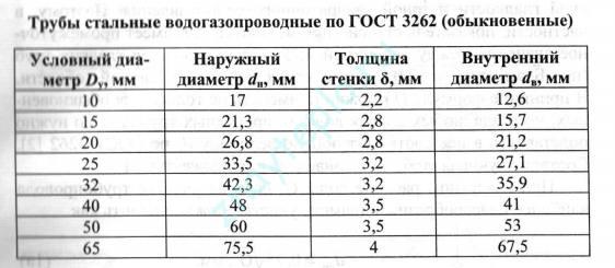
If you know the flow rate of the coolant, then there is an approximate formula for determining the inner diameter of the pipes:
d = 0.75√G mm;
Having received the result, you must use the following table to obtain the nominal diameter:
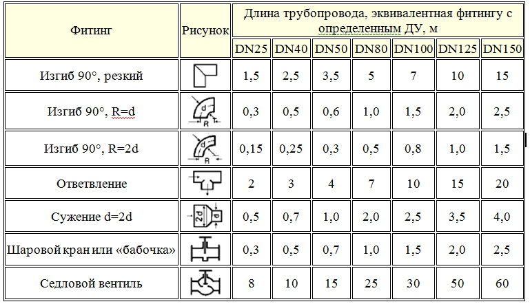
The most laborious will be the calculation of local resistances in fittings, valves and heating devices. Earlier I mentioned the coefficients of local resistance ξ, their choice is made according to the reference tables. If everything is clear with the corners and stop valves, then the choice of KMS for tees turns into a whole adventure. To make it clear what I'm talking about, let's look at the following picture:
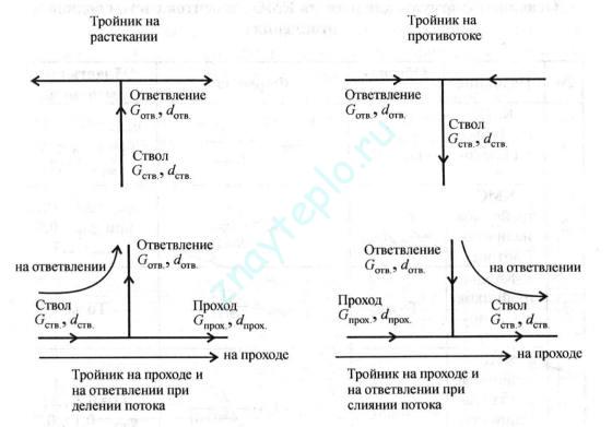
The picture shows that we have as many as 4 types of tees, each of which will have its own CCM of local resistance. The difficulty here will consist in the correct choice of the direction of the flow of the coolant. For those who really need it, I will give here a table with formulas from the book of O.D. Samarina "Hydraulic calculations of engineering systems":
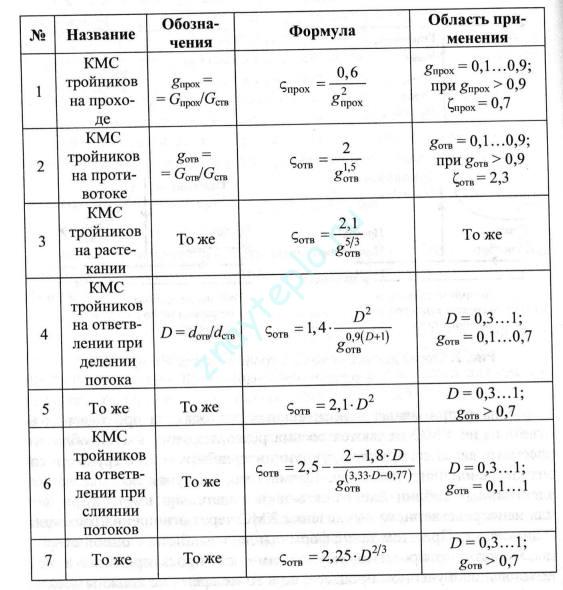
These formulas can be transferred to MathCAD or any other program and calculate the CMC with an error of up to 10%. The formulas are applicable for coolant flow velocities from 0.1 to 1.25 m / s and for pipes with a nominal diameter of up to 50 mm. Such formulas are quite suitable for heating cottages and private houses. Now let's look at some software solutions.
Programs for calculating hydraulic resistance in heating systems.
Now on the Internet you can find many different programs for calculating heating, paid and free. It is clear that paid programs have more powerful functionality than free ones and allow you to solve a wider range of tasks. It makes sense to acquire such programs for professional design engineers. For the layman who wants to independently calculate the heating system in his home, free programs will be enough. Below is a list of the most common software products:
- Valtec.PRG is a free program for calculating heating and water supply. There are possibilities for calculating warm floors and even warm walls
- HERZ is a whole family of programs. They can be used to calculate both one-pipe and two-pipe heating systems. The program has a convenient graphical presentation and the ability to split into floor plans. There is a possibility of calculating heat losses
- Stream is a domestic development, which is an integrated CAD system that can design engineering networks of any complexity. Unlike the previous ones, Stream is a paid program. Therefore, a common man in the street is unlikely to use it. It is intended for professionals.
There are several other solutions. Mostly from manufacturers of pipes and fittings. Manufacturers hone calculation programs for their materials and thus, to some extent, force them to buy their materials. This is such a marketing ploy and there is nothing wrong with it.
Classification of gas pipelines
Modern gas pipelines are a whole system of complexes of structures designed to transport combustible fuel from the places of its production to consumers. Therefore, according to their intended purpose, they are:
- Trunk - for transportation over long distances from mining sites to destinations.
- Local - for collecting, distributing and supplying gas to the objects of settlements and enterprises.

Compressor stations are being built along the main routes, which are needed to maintain working pressure in the pipes and supply gas to designated points to consumers in the required volumes, calculated in advance. In them, the gas is purified, dried, compressed and cooled, and then returned to the gas pipeline under a certain pressure required for a given section of fuel passage.
Local gas pipelines located in settlements are classified:
- By type of gas - natural, liquefied hydrocarbon, mixed, etc. can be transported.
- By pressure - in different parts of the gas there is low, medium and high pressure.
- By location - outdoor (street) and indoor, aboveground and underground.
Hydraulic calculation of a 2-pipe heating system
- Hydraulic calculation of the heating system, taking into account pipelines
- An example of a hydraulic calculation for a two-pipe gravitational heating system
Why do you need a hydraulic calculation of a two-pipe heating system Each building is individual. In this regard, heating with the determination of the amount of heat will be individual. This can be done using hydraulic calculation, while the program and the calculation table can facilitate the task.
The calculation of the heating system of a house begins with the choice of fuel, taking into account the needs and characteristics of the infrastructure of the area where the house is located.
The purpose of the hydraulic calculation, the program and table of which is on the network, is as follows:
- determining the number of heating devices that are needed;
- calculation of the diameter and number of pipelines;
- determination of the possible loss of heating.
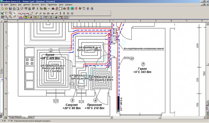
All calculations should be made according to the heating scheme with all the elements that are included in the system. A similar diagram and table must be previously compiled. To carry out a hydraulic calculation, you will need a program, an axonometric table and formulas.
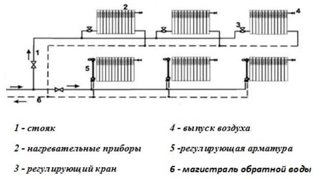
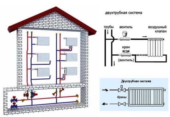
Two-pipe heating system of a private house with lower wiring.
A more loaded ring of the pipeline is taken as a design object, after which the required cross-section of the pipeline, possible pressure losses of the entire heating circuit, and the optimal surface area of the radiators are determined.
Carrying out such a calculation, for which the table and the program are used, can create a clear picture with the distribution of all the resistances in the heating circuit that exist, and also allows you to obtain accurate parameters of the temperature regime, water consumption in each part of the heating.
As a result, the hydraulic calculation should build the most optimal heating plan for your own home. Don't rely solely on your intuition. The table and calculation program will simplify the process.
Items you need:
What is hydraulic calculation and why is it needed?
Hydraulic calculation (hereinafter referred to as GR) is a mathematical algorithm, as a result of which we obtain the required pipe diameter in this system (meaning the inner diameter). In addition, it will be clear which circulation pump we need to use - the head and flow rate of the pump are determined. All this will make it possible to make the heating system economically optimal. It is made on the basis of the laws of hydraulics - a special section of physics devoted to motion and equilibrium in fluids.
Basic equations for hydraulic calculation of a gas pipeline
To calculate the movement of gas through pipes, the values of the pipe diameter, fuel consumption and head loss are taken. It is calculated depending on the nature of the movement. With laminar - calculations are performed strictly mathematically according to the formula:
Р1 - Р2 = ∆Р = (32 * μ * ω * L) / D2 kg / m2 (20), where:
- ∆Р - kgm2, head loss due to friction;
- ω - m / sec, fuel speed;
- D - m, pipeline diameter;
- L - m, pipeline length;
- μ - kg sec / m2, fluid viscosity.

In turbulent motion, it is impossible to apply accurate mathematical calculations due to the chaotic nature of the motion. Therefore, experimentally determined coefficients are used.
Calculated by the formula:
Р1 - Р2 = (λ * ω2 * L * ρ) / 2g * D (21), where:
- Р1 и Р2 - pressure at the beginning and at the end of the pipeline, kg / m2;
- λ - dimensionless coefficient of resistance;
- ω - m / sec, average gas velocity over the pipe section;
- ρ - kg / m3, fuel density;
- D - m, pipe diameter;
- g - m / sec2, acceleration of gravity.
Video: Basics of hydraulic calculation of gas pipelines
Selection of questions
- Mikhail, Lipetsk - What blades for cutting metal to use?
- Ivan, Moscow - What is the GOST of rolled metal sheet steel?
- Maxim, Tver - What racks for storage of rolled metal are better?
- Vladimir, Novosibirsk - What does ultrasonic processing of metals without the use of abrasive substances mean?
- Valery, Moscow - How to forge a knife from a bearing with your own hands?
- Stanislav, Voronezh - What equipment is used for the production of galvanized steel air ducts?
Hydraulic balancing
The balancing of pressure drops in the heating system is carried out by means of control and shut-off valves.
Hydraulic balancing of the system is based on:
- design load (mass flow rate of the coolant);
- dynamic resistance data of pipe manufacturers;
- the number of local resistances in the area under consideration;
- technical characteristics of fittings.
The setting characteristics - pressure drop, fastening, flow capacity - are set for each valve. According to them, the coefficients of the coolant flow into each riser are determined, and then into each device.
The pressure loss is directly proportional to the square of the coolant flow rate and is measured in kg / h, where
S is the product of the dynamic specific pressure, expressed in Pa / (kg / h), and the reduced coefficient for the local resistances of the section (ξpr).
The reduced coefficient ξпр is the sum of all local system resistances.
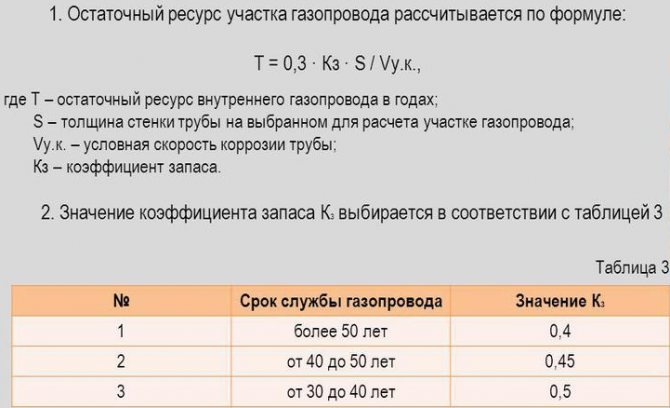
Why is it necessary to calculate the gas pipeline
Along all sections of the gas pipeline, calculations are carried out to identify places where possible resistances are likely to appear in the pipes, changing the fuel delivery rate.
If all the calculations are done correctly, then the most suitable equipment can be selected and an economical and efficient design of the entire gas system design can be created.
This will save you from unnecessary, overestimated indicators during operation and costs in construction, which could be during the planning and installation of the system without hydraulic calculation of the gas pipeline.
There is a better opportunity to select the desired size in cross-section and pipe materials for a more efficient, fast and stable supply of blue fuel to the planned points of the gas pipeline system.
The optimal operating mode of the entire gas pipeline is ensured.
Developers get financial benefits while saving on purchases of technical equipment and building materials.
The correct calculation of the gas pipeline is made, taking into account the maximum levels of fuel consumption during periods of mass consumption. All industrial, municipal, individual household needs are taken into account.
Program overview
For the convenience of calculations, amateur and professional hydraulics calculation programs are used.
The most popular is Excel.
You can use the online calculation in Excel Online, CombiMix 1.0, or the online hydraulic calculation calculator. The stationary program is selected taking into account the requirements of the project.
The main difficulty in working with such programs is the lack of knowledge of the basics of hydraulics. In some of them, there are no decoding of formulas, the features of branching of pipelines and the calculation of resistances in complex circuits are not considered.
- HERZ C.O. 3.5 - calculates using the method of specific linear pressure loss.
- DanfossCO and OvertopCO - can count natural circulation systems.
- "Flow" (Potok) - allows you to apply the calculation method with a variable (sliding) temperature difference across the risers.
It is necessary to clarify the parameters for entering data on temperature - in Kelvin / Celsius.
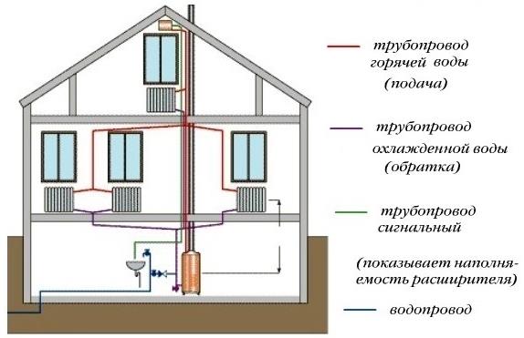
Calculation of the volume of water and the capacity of the expansion tank
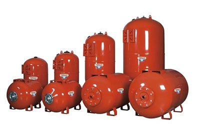
The volume of the expansion tank should be equal to 1/10 of the total volume of liquid
To calculate the performance characteristics of an expansion tank, which is mandatory for any closed-type heating system, you will need to deal with the phenomenon of an increase in the volume of liquid in it. This indicator is assessed taking into account changes in basic performance characteristics, including fluctuations in its temperature. In this case, it changes in a very wide range - from room +20 degrees and up to operating values in the range of 50-80 degrees.
It will be possible to calculate the volume of the expansion tank without unnecessary problems if you use a rough estimate that has been proven in practice. It is based on the experience of operating equipment, according to which the volume of the expansion tank is about one tenth of the total amount of coolant circulating in the system.
In this case, all its elements are taken into account, including heating radiators (batteries), as well as the water jacket of the boiler unit.To determine the exact value of the desired indicator, you will need to take the passport of the equipment in use and find in it the items regarding the capacity of the batteries and the working tank of the boiler
After determining them, it is not difficult to find excess coolant in the system. For this, the cross-sectional area of polypropylene pipes is first calculated, and then the resulting value is multiplied by the length of the pipeline. After summing up for all branches of the heating system, the numbers for the radiators and the boiler taken from the passport are added to them. One tenth is then counted from the total.
Calculation of the parameters of the coolant
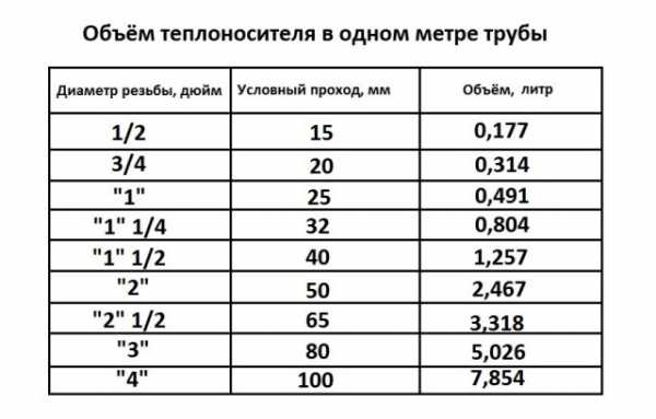
The amount of coolant in 1 m of the pipe, depending on the diameter
Calculation of the coolant is reduced to the determination of the following indicators:
- the speed of movement of water masses through the pipeline with the specified parameters;
- their average temperature;
- media consumption associated with the performance requirements of heating equipment.
The known formulas for calculating the parameters of the coolant (taking into account hydraulics) are rather complicated and inconvenient in practical use. Online calculators use a simplified approach that allows you to get a result with an acceptable error for this method.
Nevertheless, before starting the installation, it is important to worry about purchasing a pump with indicators not lower than the calculated ones. Only in this case there is confidence that the requirements for the system according to this criterion are fully met and that it is capable of heating the room to comfortable temperatures.
Hydraulic calculation of a simple composite pipeline
,
Calculations of simple pipelines are reduced to three typical tasks: determining the head (or pressure), flow rate and diameter of the pipeline. Further, the methodology for solving these problems for a simple pipeline of constant cross-section is considered.
Problem 1
... Given: the dimensions of the pipeline and

the roughness of its walls

, fluid properties

, liquid flow rate Q.
Determine the required head H (one of the values that make up the head).
Decision
... The Bernoulli equation is compiled for the flow of a given hydraulic system. Control sections are assigned. Reference plane is selected
Z(0.0)
, the initial conditions are analyzed. The Bernoulli equation is constructed taking into account the initial conditions. From the Bernoulli equation, we obtain a design formula of the type ٭. The equation is solved with respect to H. The Reynolds number Re is determined and the motion mode is set. The value is found

depending on the driving mode. H and the desired value are calculated.
Objective 2.
Given: the dimensions of the pipeline and
, the roughness of its walls

, fluid properties

, head N. Determine the flow rate Q.
Decision.
The Bernoulli equation is made taking into account the recommendations given earlier. The equation is solved with respect to the sought value Q. The resulting formula contains an unknown coefficient

depending on Re. Direct location
under the conditions of this problem, it is difficult, since for an unknown Q, Re cannot be established in advance. Therefore, the further solution of the problem is performed by the method of successive approximations.
- approximation: Re → ∞
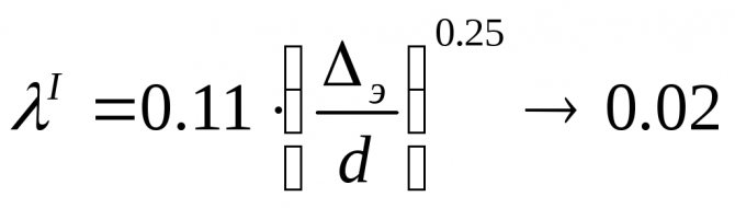
, we define

2 approximation:
, we find
λII(ReII,Δeh)
and define
Find the relative error
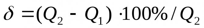
... If a
, then the solution ends (for educational problems

). Otherwise, the solution is fulfilled in the third approximation.
Objective 3.
Given: dimensions of pipelines (except for diameter d), roughness of its walls

, fluid properties
, head Н, flow rate Q. Determine the diameter of the pipeline.
Decision
... When solving this problem, difficulties arise with the direct determination of the value

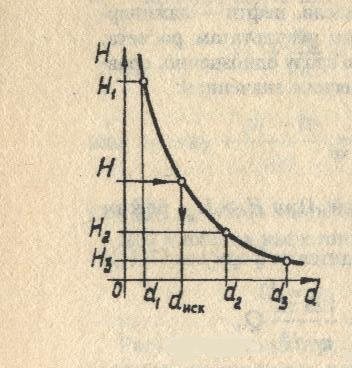
, analogous to the problem of the second type. Therefore, it is advisable to carry out the solution by the graphic-analytical method. Several diameters are specified
.For everybody
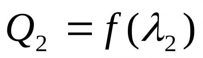
the corresponding value of the head H is found at a given flow rate Q (the problem of the first type is solved n times). Based on the results of the calculations, a graph is built
... The required diameter d is determined according to the graph, corresponding to the given value of the pressure H.
Horizontal and vertical layouts
Such a heating system is divided into horizontal and vertical schemes by the location of the pipeline connecting all devices and devices into one whole.
A vertical heating circuit differs from others in that in this case all the necessary devices are connected to a vertical riser.
Although its compilation will come out a little more expensive in the end, the resulting air stagnation and traffic jams will not interfere with stable operation. This solution is most suitable for apartment owners in a building with many floors, since all individual floors are connected separately.
A two-pipe heating system with a horizontal circuit is perfect for a one-story residential building with a relatively long length, in which it is easier and more rational to connect all available radiator compartments to a horizontal pipeline.
Both types of heating system circuits boast excellent hydraulic and temperature stability, only in the first situation, in any case, it will be necessary to calibrate the risers located vertically, and in the second - horizontal loops.
Types of heating systems
Engineering tasks of this kind are complicated by the great variety of heating systems, both in terms of scale and configuration. There are several types of heating interchanges, each of which has its own laws:
1. Two-pipe dead-end system - the most common version of the device, well suited for organizing both central and individual heating circuits.
Two-pipe dead-end heating system
2. One-pipe system or "Leningradka" It is considered the best way to construct civil heating complexes with a thermal power of up to 30–35 kW.
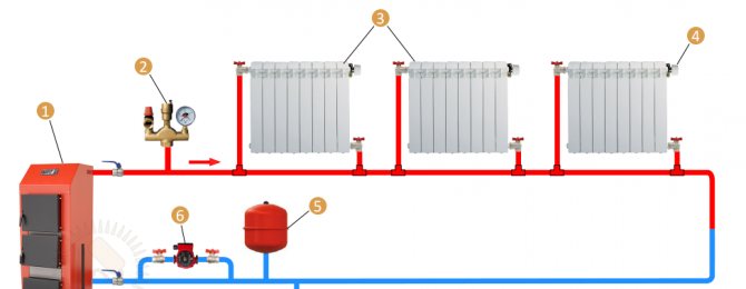
One-pipe heating system with forced circulation: 1 - heating boiler; 2 - security group; 3 - heating radiators; 4 - Mayevsky crane; 5 - expansion tank; 6 - circulation pump; 7 - drain
3. Twin-pipe system of passing type - the most material-intensive type of decoupling of heating circuits, which is distinguished by the highest known stability of operation and the quality of distribution of the coolant.
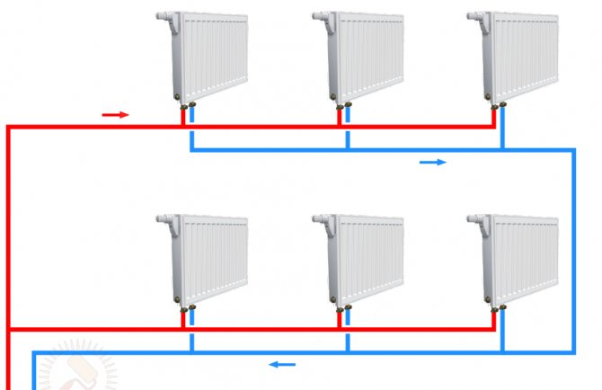
Two-pipe associated heating system (Tichelman loop)
4. Beam layout in many respects it is similar to a two-pipe ride, but at the same time all the controls of the system are brought out to one point - to the manifold assembly.
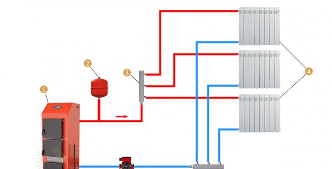
Radiation heating circuit: 1 - boiler; 2 - expansion tank; 3 - feed manifold; 4 - heating radiators; 5 - return manifold; 6 - circulation pump
Before getting down to the applied side of the calculations, there are a couple of important caveats to make. First of all, you need to learn that the key to a high-quality calculation lies in understanding the principles of operation of fluid systems at an intuitive level. Without this, consideration of each individual solution turns into an interweaving of complex mathematical calculations. The second is the practical impossibility of presenting more than basic concepts within the framework of one review; for more detailed explanations, it is better to refer to such literature on the calculation of heating systems:
- V. Pyrkov “Hydraulic regulation of heating and cooling systems. Theory and Practice "2nd edition, 2010
- R. Jaushovets "Hydraulics - the heart of water heating".
- Boiler room hydraulics manual from De Dietrich.
- A. Savelyev “Heating at home. Calculation and installation of systems ".
Determination of pressure losses in pipes
The pressure loss resistance in the circuit through which the coolant circulates is defined as their total value for all individual components. The latter include:
- loss in the primary circuit, denoted as ∆Plk;
- local costs of the heat carrier (∆Plm);
- pressure drop in special areas called “heat generators” under the designation ∆Ptg;
- losses inside the built-in heat exchange system ∆Pto.
After summing these values, the desired indicator is obtained, which characterizes the total hydraulic resistance of the system ∆Pco.
In addition to this generalized method, there are other methods for determining the head loss in polypropylene pipes. One of them is based on a comparison of two indicators tied to the beginning and end of the pipeline. In this case, the pressure loss can be calculated by simply subtracting its initial and final values, determined by two pressure gauges.
Another option for calculating the desired indicator is based on the use of a more complex formula that takes into account all the factors that affect the characteristics of the heat flow. The following ratio primarily takes into account the loss of fluid head due to the long length of the pipeline.
- h - liquid head loss, in the case under study, measured in meters.
- λ - coefficient of hydraulic resistance (or friction), determined by other calculation methods.
- L is the total length of the served pipeline, which is measured in running meters.
- D is the internal standard size of the pipe, which determines the volume of the coolant flow.
- V is the fluid flow rate, measured in standard units (meter per second).
- The g symbol is the acceleration due to gravity, equal to 9.81 m / s2.

Pressure losses occur due to the friction of the fluid against the inner surface of the pipes
Losses caused by a high coefficient of hydraulic friction are of great interest. It depends on the roughness of the inner surfaces of the pipes. The ratios used in this case are valid only for standard round tube blanks. The final formula for finding them looks like this:
- V is the speed of movement of water masses, measured in meters / second.
- D is the inner diameter, which determines the free space for the movement of the coolant.
- The coefficient in the denominator indicates the kinematic viscosity of the fluid.
The latter indicator refers to constant values and is found in special tables published in large quantities on the Internet.
Calculation of hydraulics of a water heating system
The coolant circulates through the system under pressure, which is not a constant value. It decreases due to the presence of frictional forces of water against the pipe walls, resistance on pipe fittings and fittings. The homeowner also does his part by adjusting the distribution of heat to individual rooms.
The pressure rises if the heating temperature of the coolant rises and vice versa - drops when it decreases.
To avoid unbalancing the heating system, it is necessary to create conditions under which as much coolant is supplied to each radiator as is necessary to maintain the set temperature and replenish the inevitable heat losses.
The main purpose of the hydraulic calculation is to match the estimated network costs with actual or operating costs.
At this design stage, the following are determined:
- diameter of pipes and their throughput;
- local pressure losses in individual sections of the heating system;
- hydraulic balancing requirements;
- pressure loss throughout the system (general);
- optimal flow rate of the coolant.
For the production of a hydraulic calculation, it is necessary to do some preparation:
- Collect baseline data and organize them.
- Choose a calculation method.
First of all, the designer studies the thermal engineering parameters of the facility and performs the thermal engineering calculation. As a result, he has information about the amount of heat required for each room. After that, the heating devices and the heat source are selected.
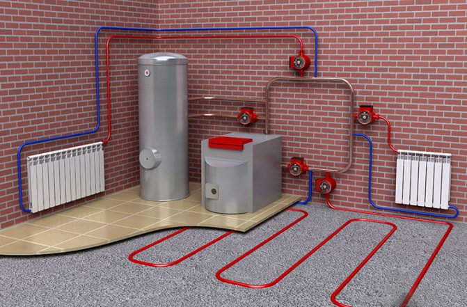
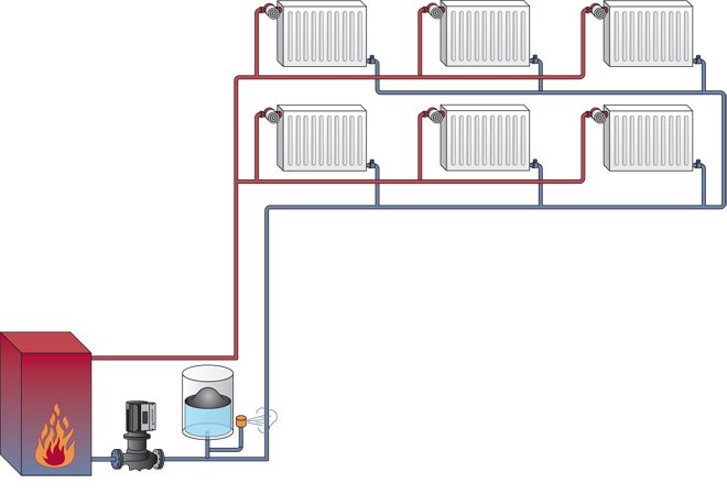
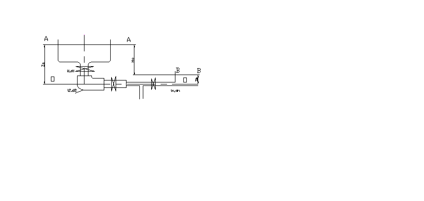
Schematic representation of a heating system in a private house
At the development stage, a decision is made on the type of heating system and the features of its balancing, pipes and fittings are selected. Upon completion, an axonometric wiring diagram is drawn up, floor plans are developed indicating:
- radiator power;
- coolant consumption;
- placement of heating equipment, etc.
All sections of the system, nodal points are marked, calculated and the length of the rings is applied to the drawing.
Calculation of the hydraulics of the heating ducts
Competently calculated hydraulics allow the correct distribution of the pipe diameter throughout the system
The hydraulic calculation of the heating system usually comes down to the selection of the diameters of pipes laid in separate sections of the network. When conducting it, the following factors must be taken into account:
- the value of pressure and its drops in the pipeline at a given rate of circulation of the coolant;
- its estimated expense;
- typical dimensions of the pipe products used.
When calculating the first of these parameters, it is important to take into account the capacity of the pumping equipment. It should be sufficient to overcome the hydraulic resistance of the heating circuits. In this case, the total length of polypropylene pipes is of decisive importance, with an increase in which the total hydraulic resistance of the systems as a whole increases.
Based on the results of the calculation, the indicators are determined that are necessary for the subsequent installation of the heating system and meet the requirements of the current standards.
In this case, the total length of polypropylene pipes is of decisive importance, with an increase in which the total hydraulic resistance of the systems as a whole increases. Based on the results of the calculation, the indicators necessary for the subsequent installation of the heating system and meeting the requirements of the current standards are determined.
What is hydraulic calculation
This is the third stage in the process of creating a heating network. It is a system of calculations that allows you to determine:
According to the data obtained, the selection of pumps is carried out.
For seasonal housing, in the absence of electricity in it, a heating system with natural circulation of the coolant is suitable (link to review).
Complex tasks - minimizing costs:
- capital - installation of pipes of optimal diameter and quality;
- operational:
- dependence of energy consumption on the hydraulic resistance of the system;
- stability and reliability;
- noiselessness.

Replacing the centralized heating mode with an individual one simplifies the calculation methodology
For offline mode, 4 methods are applicable hydraulic calculation of the heating system:
- specific losses (standard calculation of pipe diameter);
- by lengths reduced to one equivalent;
- by the characteristics of conductivity and resistance;
- comparison of dynamic pressures.
The first two methods are used with a constant temperature drop in the network.
The last two will help distribute hot water over the rings of the system if the temperature difference in the network ceases to correspond to the difference in the risers / branches.