Calculating the hydraulic and thermal parameters of engineering systems is a very demanding job. Any of the mistakes made during its implementation may result in the inability of the equipment to provide comfortable use and the need for a major overhaul of the system. At the same time, the times of mass application of typical projects are in the past, and each time the designer has to deal with the solution of a unique problem. VALTEC specialists develop tools that allow to avoid time-consuming calculations of engineering systems manually or to make them as easy as possible.
VALTEC.PRG.3.1.3. Program for heat engineering and hydraulic calculations
The VALTEC.PRG program is publicly available and makes it possible to calculate water radiator, floor and wall heating, determine the heat demand of the premises, the required consumption of cold and hot water, the volume of sewage, obtain hydraulic calculations of the internal heat and water supply networks of the facility. In addition, a user-friendly collection of reference materials is available to the user. Thanks to the intuitive interface, you can master the program without having the qualifications of a design engineer.
- Difference of version 3.1.3 from version 3.1.2:
- added a module for calculating the throughput of pipes;
- amendments were made to the module for calculating water demand according to SNiP - it is possible to continue the calculation with a probability of more than one (insufficient number of devices);
- expanded reference table "Pipes";
- updated "User's Guide".
VALTEC C.O. 3.8. Heating system design software
VALTEC C.O. - a computational and graphical program for the design of radiator and floor heating systems using VALTEC equipment, developed by the Polish company SANKOM Sp. z o.o. based on the latest version of Audytor C.O. - 3.8. The product allows you to design and regulate heating systems, to perform a full range of hydraulic and thermal calculations. The program is certified for compliance with the current building regulations of the Russian Federation and the requirements of the Voluntary Certification System of NP "AVOK".
VALTEC H
2
O 1.6. Water supply system design software
VALTEC H 2 O is a program for the design of cold and hot water supply systems using engineering plumbing VALTEC, developed by the Polish company SANKOM Sp. z o.o. based on the calculation and graphical program Audytor H 2 O 1.6. Allows you to perform a complete calculation and design of a hydraulically balanced water supply system. The program meets the requirements of the Voluntary Certification System of NP "AVOK" and SNiP 2.04.01-85 * "Internal water supply and sewerage systems of buildings".
VHM-T Service. VALTEC heat meter software
- The VHM-T Service program is designed to work with VALTEC VHM-T heat meters in terms of:
- reading the current readings and characteristics of the meter;
- work with daily, monthly and annual archives;
- formation of lists of accounting for heat energy consumption;
- setting the date, time and automatic changeover to summer / winter time (if necessary);
- meter settings for work in automated data accounting systems.
Work computer software requirements
- operating system Windows XP Service Pack 3 (32/64 bit) or higher;
- Visual C ++ Redistributable Packages for Visual Studio 2013 (free download from microsoft.com).As a rule, these packages are already present in versions of Windows 7 and higher with the latest updates.
The interaction of the working computer with the heat meter is carried out through an optoelectronic sensor with the appropriate drivers installed in the system.
Setting up the communication of the program with the counter
- Connect the optoelectronic sensor to the computer.
- On the front panel of the heat meter, hold down the button and hold it (about 8 seconds) until the symbol "=" appears in the lower right corner of the screen.
- Bring the optoelectronic sensor to the meter's optical receiver on the front panel.
- Give a command to establish communication in the program.
Emulator of control and settings of the K200M controller
Training program for users and adjusters of the modernized weather-dependent controller K200M. The device interface has been reproduced with the ability to set operating parameters and display prompts. Additional reference information: connection diagram, error codes, connection examples.
Emulator of control and settings of the K200 controller
VALTEC News widget
You can install this widget on your site - on any page, in any place convenient for visitors. This will make it possible to promptly inform customers about the appearance of new VALTEC products, with the provision of the necessary technical information. The "New items" section is replenished automatically, simultaneously with the appearance of the product in the corporate Internet catalog. A bonus for users is the ability to review previously proposed innovations.
Embed code:
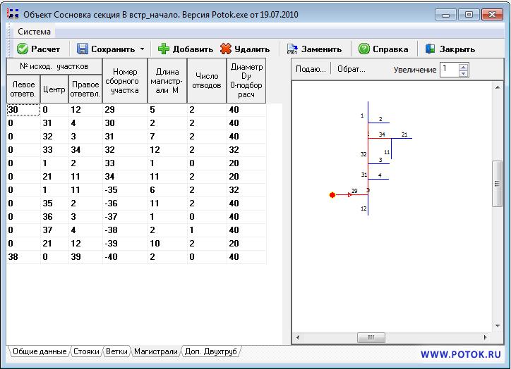
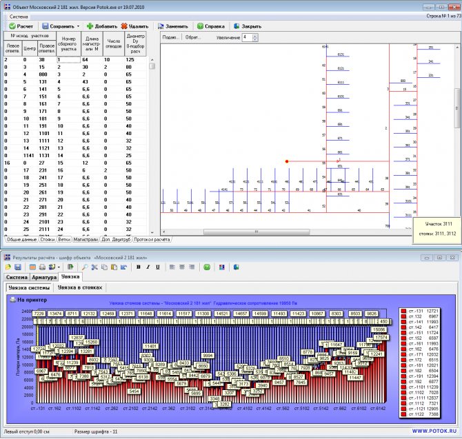
Purpose and area of application: The STREAM program is designed to perform a thermal-hydraulic calculation of 1-2 pipe, collector (baseboard, radial) heating and cooling systems or central water heating with a coolant - water or solution, with a constant or sliding temperature difference (in cases of connecting consumers through a one-pipe system) in buildings of any purpose with centralized or separate heat metering. Heat / cold is transferred to the premises by local heating devices, air heaters, fan coil units, with organized and unorganized heat metering in the system. Systems with complex configurations (one-pipe, bifilar and two-pipe risers, etc.) can be divided into separate calculation blocks with subsequent automatic combination for the purpose of hydraulic balancing and obtaining a general equipment specification in the format MS Word
and AutoCAD The program makes it possible to calculate heating systems in series - connected by the coolant, systems with upstream heating devices.
Versatility:
Manufacturers of valves in Europe, together with their products, for their successful promotion, offer their own programs for calculating systems and selecting valves. The programs are adapted to our standards. But they allow to use in the project only the products of their own company and only for a narrow range of the purpose of buildings and the design features of systems. As a rule, these are two-pipe systems. Customers of design estimates when changing a partner for the supply of equipment often put design organizations before a choice: to have in their arsenal individual and mastered software systems of all potential suppliers or to master only one for all possible design situations. And this program is
Substation STOTOK.
It can be supplied both as part of other programs of the TEPLOOV complex (TEPLOOV), and separately from the programs of the TEPLOOV complex (TEPLOOV)
Additional functions:
The designed systems can be:. Heating; ... Warm floor; ... Cold supply; ... Heat supply (heaters, technological equipment); ... With manual and automatic regulation of heat consumption and hydraulic stability.With the installation of balance valves, thermostatic valves; ... Heating with local appliances combined with heating elements, underfloor heating; ... On-site heating networks;
According to the method of accounting for heating costs a) Not organized heat metering b) Apartment-based - each apartment (office, store, etc.) has its own heat source and hydraulically heating systems are not connected to each other - count separately without combining. c) Systems with separate heat metering by owners (apartments, offices, shops, etc.) - count separately and combine.
For connection of heating devices during the formation of risers: a) one-pipe; b) two-pipe; c) bifilar;
By the location of the highways: a) with top wiring; b) with a lower wiring with conventional and P - T-shaped risers; c) with "inverted circulation"; d) with a single lower line with sequential connection of P. - shaped risers;
In the direction of water movement: a) vertical or horizontal; b) with dead-end traffic in highways; c) with passing traffic on highways; d) beam: e) collector; f) with bifilar movement in devices;
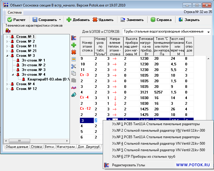
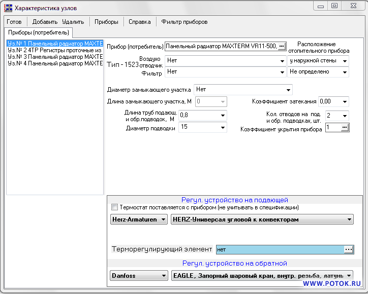
On instrument (one-sided or two-sided) nodes: a) flow-through; b) adjustable; c) with thermostats Danfoss, HERZ, Far, Watts, Comap, IMI (Heimeier, Tour Andersson
) Oventrop, etc. d) with mixing modules for underfloor heating Far, Watts, Oventrop e) flow-adjustable; f) with reduction inserts.
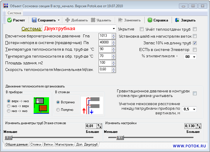
As for the heat carrier: a) network superheated water from the CHPP (with the selection of an elevator); b) local heat source; c) non-freezing solutions; By the source that stimulates circulation: a) pumping; b) gravitational;
Heating devices of the past years, produced by the CIS industry or supplied by firms from Italy, Germany, the Czech Republic, etc., can be used in the heating system. The database of devices is constantly updated by the author, including materials provided by users. In addition, the heating system with local heating devices can be combined with heat supply of air heaters and / or electric air heaters of the FC-205C - FC-805C type, heat supply of technological equipment. At the same time, a joint calculation of the system is carried out, the necessary design materials are prepared.
Double regulation valves, three-way valves, thermostats and valves are used as shut-off and control valves in the units of heating devices. It is recommended that when designing new systems, it is mandatory to install thermostats at the devices, and automatic balance valves on the risers. This will allow avoiding the installation of throttle washers, eliminating design flaws, calculation and installation, and providing heat savings for the entire heating period, which will very quickly cover some increase in capital costs. The use of two-pipe routing also leads to a significant reduction in operating costs.
The calculation of heating systems is carried out taking into account additional heat losses due to: a) placement of devices near the outer walls; b) cooling of water in uninsulated main pipelines; c) by rounding the heating surface of the devices.
In this regard, in order to partially compensate for additional heat losses by the projected system, an increase in the estimated amount of heat (coolant) at the input is provided.
The diameter of any section can be given
, or defined
by calculation
... The diameters of pipelines can be determined by the program at least as specified by the user. When selecting the diameters of the main lines, it is envisaged to comply with the telescopic condition.
Reference and technical information required to solve the problem includes an assortment of various pipes, a base of heating devices, heat engineering data of shut-off and control valves. All reference and technical information is taken out of the program and formed into a library of technical information with the possibility of constant adjustment as the industry masters the release of new products and materials.
When designing systems with a passing movement of the coolant in the branches, with risers for 1-2 floors, with sharply differently loaded risers in the system, etc. it is advisable to connect the washer installation unit on the branch lines if automatic balance valves are not used.The program is configured to design without installing washers on the highways.
Input data
Data on the geometry of the system, loads on devices, information on equipment suppliers and the accepted nomenclature of products, material of pipes of risers, main lines. Data entry is done in a very simple and well-thought-out manner. ()
Output
All the calculated characteristics of the system in tabular form for entering on plans and diagrams, automatic generation of passports and specifications of the system equipment in Word format.
Contents of delivery
Program, program documentation, on CD-ROM (CD), electronic security key (network or local version) ..
Hardly anyone would argue that individual heating is in many ways superior to centralized heating. Many of us are trying with all our might to heat the house / apartment on our own, and the reason for this is often more than trivial: we want to combine maximum comfort with economy. And even significant material costs at the first stages cannot become an obstacle, especially since everything will pay off very quickly due to the modern approach to regulating the heat exchange process, which is used in heating equipment today.
Sounds beautiful, but is it realistic to bring all this to life? More than, but only with properly equipped heating. And here the hydraulic calculation of the heating system plays a special role.
What is the essence of such a calculation?
The main difference between modern systems is a special mechanism that provides a hydraulic mode. Modern developments and high-quality materials that are used today in heating systems make it possible to respond in a timely manner to the slightest temperature fluctuation. It would seem that this is very beneficial: energy is saved, and therefore, our heating costs are minimized. But on the other hand, such equipment requires special knowledge regarding the use of high-tech control valves, as well as other elements in the arrangement of the system.
Important information! The combination of hydraulic calculation and control valves is the key to the efficiency and operability of modern heating systems.
There are certain circumstances that require us to comply with the above conditions.
- The coolant must be supplied to the heating devices in the proper amount - this way you will achieve a heat balance, provided that you set the temperature in the building, and the outside temperature will change.
- Lack of noise, durability and stability of the heating system.
- Minimum operating costs, in particular, electricity, which would be directed to overcome the hydraulic resistance of the pipeline.
- The cost of installing the system should be kept to a minimum, which depends to a large extent on the diameter of the pipeline.
Video instruction
Hydraulic calculation of the heating system, taking into account pipelines
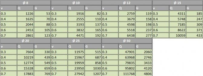
When carrying out all calculations, the main hydraulic parameters will be used, including the hydraulic resistance of pipelines and fittings, the flow rate of the coolant, the speed of the coolant, as well as the table and the program. There is a complete relationship between such parameters. It is necessary to rely on this when carrying out calculations.
Example: if the velocity of the heat carrier is increased, the hydraulic resistance at the pipeline will also increase. If the flow rate of the coolant is increased, both the speed of the coolant and the hydraulic resistance may increase at the same time. The larger the diameter of the pipeline, the lower the speed of the coolant and the hydraulic resistance will be. Based on the analysis of such relationships, it is possible to turn the hydraulic calculation into an analysis of the reliability and efficiency parameters of the entire system, which can help reduce the cost of materials that are used. It is worth remembering that the hydraulic characteristics are not constant, with which nomograms can help.Hydraulic calculation of a water heating system: heat carrier flow
The flow rate of the coolant will directly depend on what heat load will be on the coolant when it moves heat to the heating device from the heat generator. This criterion contains a table and a program.
Hydraulic calculation implies the determination of the flow rate of the coolant in relation to a given section. The calculated section will be a section that has a stable coolant flow rate and a constant diameter.
An example of a short calculation will contain a branch that includes 10 kilowatt radiators, while the coolant flow is calculated for the transfer of thermal energy at the level of 10 kW. In this case, the calculated section is a cut from the radiator, which is the first in the branch, to the heat generator. However, this is only under the condition that such a section will be characterized by a constant diameter. The second section will be located between the first and second radiators. If in the first case the consumption of 10-kilowatt heat energy transfer is calculated, then in the second section the amount of energy that is calculated will be 9 kW with a possible gradual decrease as such calculations are carried out.
The hydraulic resistance will be calculated simultaneously up to the return and supply pipelines.
The hydraulic calculation of such heating consists in calculating the flow rate of the coolant according to the formula for the calculated area:
G uch = (3.6 * Q uch) / (c * (t r-t o)), where Q uch is the heat load of the area, which is calculated (in W). This example contains a heat load per section of 10,000 W or 10 kW, s - (specific heat capacity for water) constant, which is 4.2 kJ (kg * ° C), tr is the temperature of the heat carrier hot in the heating system, to - the temperature of the cold heat carrier in the heating system. Hydraulic calculation of the heating gravity system: flow rate of the heating medium
The threshold value 0.2-0.26 m / s should be taken as the minimum speed of the coolant. If the speed is lower, excess air can be released from the coolant, which can lead to the appearance of air locks. This, in turn, will cause a complete or partial failure of the heating system. Regarding the upper threshold, the speed of the coolant should be 0.6-1.5 m / s. If the speed does not rise above this indicator, hydraulic noise will not be able to form in the pipeline. Practice shows that the optimal speed range for heating systems is 0.4-0.7 m / s.
If there is a need for a more accurate calculation of the speed range of the coolant, it will be necessary to take into account the parameters of the materials of the pipelines in the heating system. More precisely, a roughness factor will be needed for the internal piping surfaces. For example, if we are talking about steel pipelines, the optimal speed of the coolant will be at the level of 0.26-0.5 m / s. If there is a polymer or copper pipeline, the speed can be increased to 0.26-0.7 m / s. If you want to play it safe, you need to carefully read what speed is recommended by manufacturers of equipment for heating systems.
A more accurate range of the speed of the coolant, which is recommended, will depend on the material of the pipelines that are used in the heating system, more precisely on the roughness coefficient of the inner surface of the pipeline. For example, for steel pipelines, it is recommended to adhere to a coolant speed of 0.26 to 0.5 m / s. For polymer and copper (polyethylene, polypropylene, metal-plastic pipelines) from 0.26 to 0.7 m / s. It makes sense to use the manufacturer's recommendations, if available. Calculation of the hydraulic resistance of the heating gravity system: pressure loss
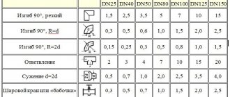
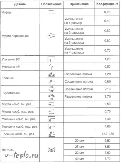
Pressure losses in certain areas, which can be called the term "hydraulic resistance", represent the total sum of all losses due to hydraulic friction and local resistances. Such an indicator, which is measured in Pa, can be calculated using the formula:
Ruch = R * l + ((p * v2) / 2) * E3, where v is the velocity of the coolant that is used (measured in m / s), p is the density of the coolant (measured in kg / m³), R is the pressure loss in the pipeline (measured in Pa / m), l is the estimated length of the pipeline in the section (measured in m), E3 is the sum of all local resistance coefficients in the equipped section and shut-off and control valves.
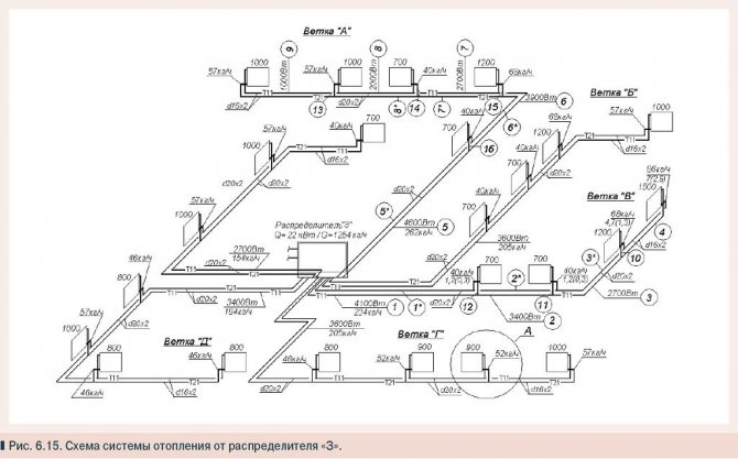
The total hydraulic resistance is the sum of the resistances of the calculated sections. The data is contained in the following table (PICTURE 6). Hydraulic calculation of a two-pipe gravitational heating system: selection of the main branch
If the hydraulic system is characterized by a passing movement of the coolant, for a two-pipe system it is necessary to select the ring of the most loaded riser through the heating device located below.
If the system is characterized by a dead-end movement of the heat carrier, for a two-pipe design, it is necessary to select the lower heater ring for the most loaded of the most distant risers.
If we are talking about a horizontal heating structure, you need to select a ring through the busiest branch, which belongs to the lower floor.
1poteply.ru
for "Hydraulic calculation of pipelines"
- Alexey 28 Aug 2014 00:28
- Alexander Vorobiev 28 Aug 2014 20:46
- Nikolay 07 Nov 2014 02:10
- Anatoly Jul 14 2020 19:34
- Elena 25 Aug 2020 16:41
- Alexander Vorobyov 25 Aug 2020 20:53
- Igor Sep 21 2020 02:09
- Alexander Vorobyov 21 Sep 2020 13:50
- Igor 21 Sep 2020 21:47
- Alexander Vorobyov 21 Sep 2020 22:07
- Oleksandr 28 Oct 2020 04:08
- Alexander Vorobyov 31 Oct 2020 20:32
- Igor Dec 21 2020 03:47
- Alexander Vorobiev Dec 21 2020 09:00
- Vladimir 02 Dec 2020 18:38
- Alexander Vorobyov 03 Dec 2020 10:49
- Dmitry Dec 11 2020 10:10
- Alexander Vorobiev Dec 11 2020 12:29
- Dmitry 18 Dec 2020 11:42
- Alexander Vorobiev Dec 18 2020 12:32
- Maria Jan 17 2020 16:49
- Alexander Vorobyov 17 Jan 2020 19:42
- Jose Feb 17 2020 20:06
- Andrey Mar 27 2020 17:59
- Igor 16 May 2020 08:02
- Alexander Vorobyov May 16, 2020 17:35
- Sergey 17 June 2020 22:46
- Alexander Vorobyov 18 June 2020 10:05
- Larissa 09 Sep 2020 18:13
- Alexander Vorobyov 10 Sep 2020 11:21
- Vadim 19 Sep 2020 23:14
- Alexander Vorobyov 20 Sep 2020 19:48
- Dmitry Feb 17 2020 00:39
- Nikita 22 Mar 2020 23:46
- Alexander Vorobyov Mar 24 2020 11:26
- Denis Mar 28 2020 18:11
- Alexander Vorobiev March 28 2020 19:09
- Evgeniy 25 Apr 2020 17:08
- Alexander Vorobyov 25 Apr 2020 18:41
- Elena 04 2020 Jun 20:02
- Alexander Vorobyov 04 June 2020 21:30
- Lenar 12 Jul 2020 16:03
- Alexander Vorobyov 12 Jul 2020 16:18
- Mikhail Subbotin Nov 09 2020 15:22
- Mikhail Subbotin Nov 09 2020 15:24
- Alexander Vorobyov Nov 09 2020 15:40
your feedback
al-vo.ru
What does hydraulic calculation give us?
- Loss of the carrier of heat and pressure in the system itself.
- The required pipe diameter in the most critical sections of the pipeline. In this case, it is necessary to take into account what are the required and materially reasonable rates of movement of the coolant.
- Hydraulic connection of all branches of the heating system. At the same time, in order to balance the system in different modes of operation, it is necessary to use the previously mentioned adjustment valves.
- Loss of pressure on other sections of the line.
Important information! During the design and installation of the heating system, hydraulic calculation is considered the most laborious and crucial stage of work.
But before making a hydraulic calculation of the heating system, you must first perform a number of procedures.
Calculations and work to be done in advance
Hydraulic calculation is the most time consuming and complex design stage.
Therefore, before calculating the heating in the house, you need to perform a number of calculations.
- First, the balance of heated rooms and premises is determined.
- Secondly, it is necessary to select the type of heat exchangers or heating devices, as well as to place them on the plan of the house.
- Thirdly, the calculation of heating a private house assumes that a choice has already been made regarding the configuration of the system, the types of pipelines and fittings (regulating and shut-off).
- Fourthly, a drawing of the heating system must be made. It is best if it is an axonometric diagram. It should indicate the numbers, the length of the calculated sections and the heat loads.
- Fifth, the main circulation ring is installed. This is a closed loop that includes successive pipe sections directed to the device riser (when considering a one-pipe system) or to the most distant heating device (if there is a two-pipe system) and back to the heat source.
The calculation of heating in a wooden house is carried out in the same way as in a brick or in any other country cottage.
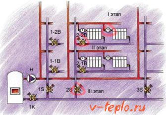
Heating system hydraulics sample
Now let's take an example of how you need to carry out the hydraulic calculation of the heating system. To do this, we take that section of the main line on which relatively stable heat losses are observed. It is characteristic that the diameter of the pipeline will not change.
To determine such a site, we need to rely on information about the heat balance in the building where the system itself will be located. Remember that such areas should be numbered starting from the heat generator. With regards to the nodes that will be located in the supply area, they should be signed in capital letters.
If there are no such nodes on the highway, then we only mark them with small strokes. For the anchor points (they will be in the branched sections), we use Arabic numerals. If a horizontal heating system is used, then the number at each such point will indicate the floor number. The collection points should also be marked with small strokes. Note that each of these numbers must necessarily consist of two numbers: one for the beginning of the section, the second, therefore, for its end.
Resistance table
Important information! If a vertical type system is calculated, then all risers should also be marked with Arabic numerals to go strictly clockwise.
Draw up a detailed plan-estimate in advance to make it easier to determine the total length of the highway. The accuracy of the estimate is not just a word, the accuracy must be observed up to ten centimeters!
Results.
The obtained values of pressure losses in the pipeline, calculated by two methods, differ in our example by 15 ... 17%! Looking at other examples, you can see that the difference sometimes reaches 50%! In this case, the values obtained according to the formulas of theoretical hydraulics are always less than the results according to SNiP 2.04.02–84. I am inclined to believe that the first calculation is more accurate, and SNiP 2.04.02–84 is "insured". Perhaps I am wrong in my conclusions. It should be noted that hydraulic calculations of pipelines are difficult to accurately simulate and are based mainly on dependencies obtained from experiments.
In any case, having two results, it is easier to make the right decision you need.
Remember to add (or subtract) static pressure to the results when hydraulically sizing pipelines with a difference in inlet and outlet heights. For water - a height difference of 10 meters ≈ 1 kg / cm2.
Dear readers, your thoughts, comments and suggestions are always interesting to colleagues and the author. Write them below, in the comments to the article!
ask respecting the author's work download file after subscription on article announcements!
Do not forget confirm subscription by clicking on the link in the letter that will come to you at the specified mail (may come to the "Spam" folder) !!!
Link to download the file: gidravlicheskiy-raschet-truboprovodov (xls 57,5KB).
Read an important and, I think, an interesting continuation of the topic here.
More blog articles
To the main
Articles with related topics
- Hydraulic resistance
- Calculation of a pipeline with parallel sections
About special programs for calculations
There are special programs that can be used in order to significantly simplify the hydraulic calculation of the heating system. Of course, there are not so many of them, nevertheless, they are, moreover, very effective. Some of them are free to download, while others are only available in trial versions. Be that as it may, and all the necessary calculations can be done without any special investment.
Oventrop CO program
This is a completely free program that is widely used to calculate a country house. You just need to pre-set all the necessary settings and specify heating devices, pipes - then you can easily work out new systems. Moreover, if you wish, you can correct the already existing system. This is done in the following way: the power of existing devices is selected in accordance with the requirements of the heated building.
Both design methods are perfectly combined in a single software, which makes it possible to create new designs and adjust old ones. Regardless of the method, the program itself selects the reinforcement setting. With regard to the calculations we are interested in, Oventrop CO offers simply unlimited possibilities - from the analysis of the flow rate of the coolant to the diameter of the pipes. All information is displayed in the form of figures, tables or diagrams.
HERZ C.O.
Another representative of free programs that allows you to calculate any kind of heating system. The utility is characterized by the fact that it allows such calculations to be performed even in new or recently reconstructed facilities in which glycol is the coolant. Conforms to all international requirements, therefore, has all the necessary certificates.
Below are the main features that the German HERZ C.O.
- Select the pipeline by diameter.
- Reduce the pressure in the circulation rings by automatic selection of valve parameters.
- Adjust pressure difference “regulators”.
- Take into account the required parameters of the thermostat valves.
- Analyze the future flow rate of the coolant, as well as determine the pressure drop in the system.
- Calculate the hydraulic resistance of the circulation rings.
To make it easier for you to use the program, all information can be entered graphically. As a result, the utility will give you a floor plan of the building.
Important information! Another distinguishing feature of the program is the so-called contextual help. It makes it possible to learn more about the command being entered or any indicator.
It is also possible to open several windows at once (which is very rare for this kind of products), so that you can study several types of information at the same time. It is possible to work with printers and plotters - it is extremely simply organized, each sheet that is planned to be printed can be previewed.
Instal-Therm HCR Program
Another utility that makes it possible with the utmost accuracy to calculate a surface or radiator system. It does not go alone, but comes in a package, which, in addition to it, also includes programs for creating drawings, designing a hot / cold water supply, and also for determining heat loss.
Below we have given the main computing capabilities of this program.
- Selection of the diameter of the future pipeline.
- Selection of heating devices, which takes into account the cooling of the coolant in the line.
- Sizing couplings, fittings and tees.
- Hydraulic calculation of the heating system.
- Selection of the power of the pumps (in other words, the height of the liquid rise), which are installed around the perimeter.
- Automatic regulation of the required temperature.
It is characteristic that the program is available for free only in a demo version, which has a number of limitations. First of all, in it (as well as in most free utilities) you can neither import the results obtained, nor print them. In addition, you can only create three projects - more requires purchasing the program. But! You can modify these three projects an unlimited number of times! finally, all projects are saved in a special modified format that no licensed or, of course, trial software can read.
As a conclusion
Today, regulating heating systems, in which the heat value is constantly changing, need constant monitoring and control. But if you do not know the modern market, then you will hardly be able to choose the right fittings. So the ideal option for calculating the system is to use one of the special programs, which would include a large catalog of parameters and data. Not only the heating efficiency, but also the initial financial costs of its installation will depend on how correctly the calculation is made.
>> Program for calculating the heating system
There are special programs, calculators, including on-line, to calculate the parameters necessary for the design of a home heating system. I prefer the Valtec heating system calculation program. It has all the necessary tools to determine the heat loss of the house and the hydraulic resistance of the system.
Before we start calculating the heating system, let's get acquainted with the capabilities of the Valtec program.
Unpack the downloaded archive with the program. You will have a folder where you need to go and run the program by double-clicking on the icon:
1. Program icon for calculating the heating system.
The working window of the program will immediately open, since the program does not require installation:
2. Program window for calculating the heating system.
So what can you do with Valtec?
Calculation program HERZ HERZ official website of HERZ Armaturen in our country
We also inform you that the HERZ fittings database has been updated in the RAUCAD program. For questions about obtaining a new base, please contact the engineer of the technical support group of the department of internal engineering systems, Moscow, tel. (ext. 203).
HERZ C.O.
HERZ C.O. it is necessary for the hydraulic calculation of single and heating systems with two pipes and cooling, during the design of new systems, and also for the regulation of existing ones in reconstructed buildings (for example, after the building has been insulated), it has the ability to calculate systems where glycolic mixtures are the heat carrier.
The program makes it possible to perform completely all hydraulic calculations of equipment, within the framework of which:
the diameters of the pipelines are selected; analysis of water consumption in the designed equipment; the pressure loss in the equipment is determined; the hydraulic resistance of the circulation rings is determined, taking into account the gravitational pressure associated with the cooling of water in pipelines and heat consumers; the settings of the pressure difference regulators are selected, installed in places selected by the designer (the base of the risers, branches, etc.); the required authority of the thermostatic valves is taken into account; the excess pressure in the circulation rings is reduced by selecting the presettings of the valves; taking into account the need to equip the appropriate resistance in terms of hydraulics of the section with the heat consumer.
The program uses many solutions to facilitate and improve the work. The most important of them are:
- graphical data entry process;
- presentation of the results of calculations on the diagram and floor plans;
- developed context-sensitive help system, which calls up information about both individual program commands and hints regarding the input data;
- multi-window environment, it allows you to simultaneously view many types of data, totals, etc .;
- the usual cooperation with the printer and plotter, the function of previewing pages before printing and output to the plotter;
- luxurious error diagnostics and the function of their automated search, both in the table and in the diagram;
- quick access to catalog data of pipes, radiators and fittings.
HERZ OZC Program
The HERZ OZC program is used to determine the calculated heat loss of individual rooms in a building, and also of the entire structure. The calculation is carried out in accordance with appropriate standards. The program executes:
- calculation of heat transfer coefficients for walls, floors, roofs and ceilings between the upper floor and the attic;
- calculation of heat loss for individual premises;
- calculation of heat loss of the entire structure.
The program uses many solutions to facilitate and improve the work. The most important of them are:
- developed help system;
- luxurious catalog of materials for construction;
- function of automated determination of heat transfer resistances, resistances of air layers of ceilings between the upper floor and the attic, soil resistance;
- the function of automatically creating the next floors, copying rooms, and also selecting rooms, for example, if you need to call another room when entering data about a room;
- the option of automated distribution of heat losses from a room with a small demand for heat output (for example, a corridor) to adjacent rooms, which makes it possible to directly transfer the calculation results to the HERZ C.O.
The program provides an opportunity for calculating the heat loss of huge buildings.
The following are data restrictions:
Maximum number of defined fences: 16300 Maximum number of layers in one fence: 16300 Maximum number of rooms: 16300 Maximum number of fences in one room: 16300
The results of heat loss calculations are the output data for the HERZ C.O program used for the design of district heating systems.
Tools in the Valtec Main Menu
Valtec, like any other program, has a main menu at the top.
We click on the "File" button and in the submenu that opens, we see the standard tools known to any computer user from other programs:
The program "Calculator" built into Windows is launched to perform calculations:
With the help of the "Converter" we will convert one unit of measurement to another:
There are three columns here:
In the extreme left, we select the physical quantity with which we work, for example, pressure. In the middle column - the unit from which you need to translate (for example, Pascals - Pa), and in the right - into which you need to translate (for example, in technical atmospheres). In the upper left corner of the calculator there are two lines, in the upper one we will drive the value obtained during the calculations, and in the lower one the translation into the required units of measurement will be immediately displayed ... But we will talk about all this in due time, when it comes to practice.
In the meantime, we continue to get acquainted with the "Tools" menu. "Form generator":
This is necessary for designers who carry out projects to order. If we do heating only in our own house, then the "Form Generator" is unnecessary for us.
The next button in the main menu of Valtec is Styles:
To control the appearance of the program window, it adjusts to the software that is installed on your computer. For me, such an unnecessary gadget, because I am one of those for whom the main thing is not "checkers", but to get there. And you decide for yourself.
Let's take a closer look at the tools under this button.
In "Climatology" we select the construction area:
Heat loss in a house depends not only on the materials of the walls and other structures, but also on the climate of the area where the building is located.Consequently, the requirements for the heating system depend on the climate.
In the left column we find the area in which we live (republic, region, region, city). If our settlement is not here, then we choose the closest one.
"Materials". Listed here are the parameters of different building materials used in the construction of houses. That is why, when collecting initial data (see previous design materials), we listed the materials for walls, floors, ceilings:
Openings tool. Here is information on door and window openings:
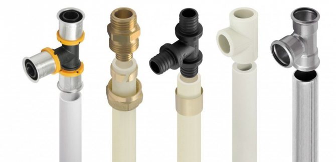
"Pipes". Here you can find information about the parameters of pipes used in heating systems: internal and external dimensions, resistance coefficients, roughness of internal surfaces:
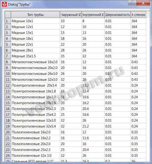
We will need this for hydraulic calculations - to determine the power of the circulation pump.
"Heat carriers". Actually, there is nothing here except the characteristics of those coolants that can be poured into the heating system of the house:
These characteristics are heat capacity, density, viscosity.
Water is not always used as a heat carrier; it happens that antifreezes are poured into the system, which are called "non-freezing" in the common people. We will talk about the choice of a coolant in a separate article.
"Consumers" are not needed to calculate the heating system, since this tool for calculating water supply systems:
"KMS" (coefficients of local resistance):
Any heating device (radiator, valve, thermostat, etc.) creates resistance for the movement of the coolant, and these resistances must be taken into account in order to correctly select the power of the circulation pump.
"Devices according to DIN". This, like Consumers, is more about water supply systems: