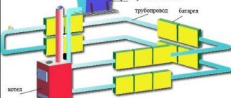
Online calculator for calculating cooling capacity
To independently select the power of a home air conditioner, use the simplified method for calculating the area of the refrigerated room, implemented in the calculator. The nuances of the online program and the entered parameters are described below in the instructions.
Note. The program is suitable for calculating the performance of household chillers and split systems installed in small offices. Air conditioning of premises in industrial buildings is a more complex task, solved with the help of specialized software systems or the calculation method of SNiP.
Heat gain from equipment
Heat gains from equipment and electric motors directly depend on their power and are determined from the expression:
Q = N * (1-efficiency * k3),
or Q = 1000 * N * k1 * k2 * k3 * kt
where N is the power of the equipment, kWk1, k2, k3 are the load factors (0.9 - 0.4), demand (0.9 - 0.7) and simultaneous operation (1 - 0.3),
kt - coefficient of heat transfer to the room 0.1 - 0.95
These coefficients are not the same for different equipment and are taken from different reference books. In practice, all the coefficients and efficiency of the devices are specified in the terms of reference. In industrial ventilation, there can be more heat gains from equipment than from anything else.
Dependence of the efficiency of an electric motor on its power:
N <0.5 0.5-5 5-10 10-28 28-50> 50
η 0.75 0.84 0.85 0.88 0.9 0.92 As for household ventilation, it is advisable to take the power and air flow rate from the equipment passports, but it happens that there is no data and if the industry cannot do without technologists, then here it is allowed to take approximate values for heat gains from equipment, which can be found in all kinds of reference books and manuals, for example:
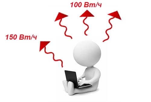
- Heat dissipation of computers 300-400 W
- coffee machines 300 W
- laser printers 400w
- electric kettle 900-1500 W
- copier 500-600 W
- deep fryers 2750-4050 W
- servers 500-100 W
- toaster 1100-1250 W
- TV set 150 W
- grill 13,500 W / m2 surface
- refrigerator 150 W
- electric stoves 900-1500 W / m2 surface
When there is an exhaust hood in the kitchen, the heat gain from the stove is reduced by 1.4.
Instructions for using the program
Now we will explain step by step how to calculate the power of the air conditioner on the presented calculator:
- In the first 2 fields enter the values for the area of the room in square meters and the height of the ceiling.
- Select the degree of illumination (sun exposure) through the window openings. The sunlight penetrating into the room additionally heats the air - this factor must be taken into account.
- In the next drop-down menu, select the number of tenants staying in the room for a long time.
- On the remaining tabs, select the number of TVs and personal computers in the air conditioning zone. During operation, these household appliances also generate heat and are subject to accounting.
- If a refrigerator is installed in the room, enter the value of the electrical power of the household appliance in the penultimate field. The characteristic is easy to learn from the instruction manual of the product
- The last tab allows you to take into account the supply air entering the cooling zone due to ventilation. According to regulatory documents, the recommended multiplicity for residential premises is 1-1.5.
For reference. The air exchange rate shows how many times during one hour the air in the room is completely renewed.
Let's explain some of the nuances of the correct filling of the fields and the selection of tabs. When specifying the number of computers and televisions, consider the simultaneous operation of them.For example, one tenant rarely uses both appliances at the same time.
Accordingly, to determine the required power of the split system, a unit of household appliances that consumes more energy is selected - a computer. The heat dissipation of the TV receiver is not taken into account.
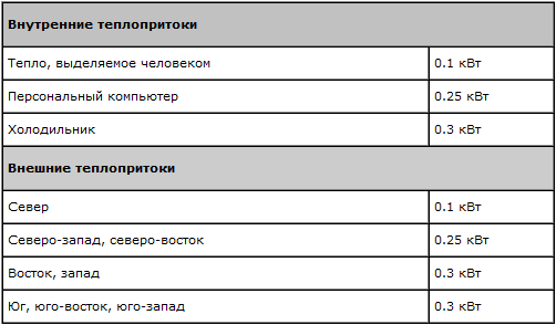
The calculator contains the following values for heat transfer from household appliances:
- TV set - 0.2 kW;
- personal computer - 0.3 kW;
- Since the refrigerator converts about 30% of the consumed electricity into heat, the program includes 1/3 of the entered figure in the calculations.
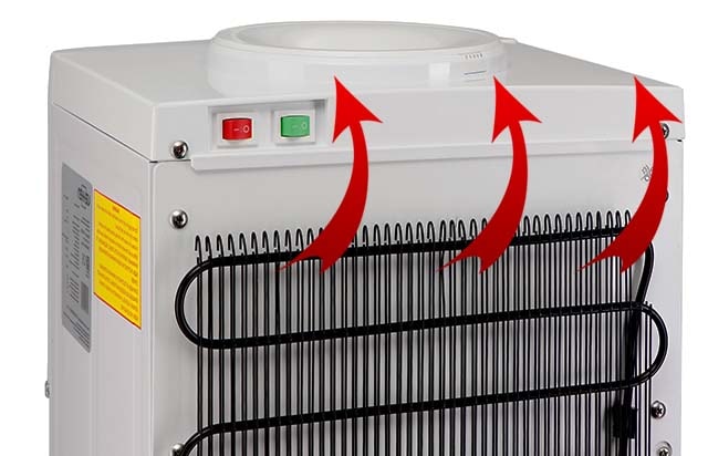
The compressor and radiator of a conventional refrigerator give off heat to the ambient air.
Advice. The heat dissipation of your equipment may differ from the indicated values. Example: the consumption of a gaming computer with a powerful video processor reaches 500-600 W, a laptop - 50-150 W. Knowing the numbers in the program, it is easy to find the necessary values: for a gaming PC, choose 2 standard computers, instead of a laptop, take 1 TV receiver.
The calculator allows you to exclude heat gain from the supply air, but choosing this tab is not entirely correct. Air currents in any case circulate through the dwelling, bringing heat from other rooms, such as the kitchen. It is better to play it safe and include them in the calculation of the air conditioner, so that its performance is sufficient to create a comfortable temperature.
The main power calculation result is measured in kilowatts, the secondary result is in British Thermal Units (BTU). The ratio is as follows: 1 kW ≈ 3412 BTU or 3.412 kBTU. How to choose a split-system based on the obtained figures, read on.
Typical calculation of the power of the air conditioner
A typical calculation allows you to find the capacity of an air conditioner for a small room: a separate room in an apartment or cottage, an office with an area of up to 50 - 70 sq. m and other premises located in capital buildings. Calculation of cooling capacity Q
(in kilowatts) is produced according to the following method:
Q = Q1 + Q2 + Q3
| Q1 - heat gains from the window, walls, floor and ceiling. | Q1 = S * h * q / 1000, where S is the area of the room (sq. M); h is the height of the room (m); q - coefficient equal to 30 - 40 W / kb. m: q = 30 for a shaded room; q = 35 at medium illumination; q = 40 for rooms with a lot of sunlight. If direct sunlight enters the room, then the windows should have light curtains or blinds. |
| Q2 is the sum of heat gains from people. | Heat gains from an adult: 0.1 kW - at rest; 0.13 kW - with light movement; 0.2 kW - with physical activity; |
| Q3 - the sum of heat gains from household appliances. | Heat gains from household appliances: 0.3 kW - from a computer; 0.2 kW - from the TV; For other appliances, it can be assumed that they generate 30% of the maximum power consumption in the form of heat (that is, it is assumed that the average power consumption is 30% of the maximum). |
The power of the air conditioner must be within the range Qrange
from
–5%
before
+15%
design capacity
Q
.
An example of a typical calculation of the power of an air conditioner
Let's calculate the capacity of the air conditioner for a living room with an area of 26 sq. m with a ceiling height of 2.75 m in which one person lives, and also has a computer, TV and a small refrigerator with a maximum power consumption of 165 watts. The room is located on the sunny side. The computer and the TV do not work at the same time, as they are used by the same person.
- First, we determine the heat gains from the window, walls, floor and ceiling. Coefficient q
choose equal
40
, since the room is located on the sunny side:Q1 = S * h * q / 1000 = 26 sq. m * 2.75 m * 40/1000 = 2.86 kW
.
- Heat gains from one person in a calm state will be 0.1 kW
.
Q2 = 0.1 kW - Next, we will find heat gains from household appliances. Since the computer and the TV do not work at the same time, only one of these devices must be taken into account in the calculations, namely the one that generates more heat. This is a computer, the heat dissipation from which is 0.3 kW
... The refrigerator generates about 30% of the maximum power consumption in the form of heat, that is
0.165 kW * 30% / 100% ≈ 0.05 kW
.
Q3 = 0.3 kW + 0.05 kW = 0.35 kW - Now we can determine the estimated capacity of the air conditioner: Q = Q1 + Q2 + Q3 = 2.86 kW + 0.1 kW + 0.35 kW = 3.31 kW
- Recommended power range Qrange
(from
-5%
before
+15%
design capacity
Q
):
3.14 kW range
It remains for us to choose a model of suitable power. Most manufacturers produce split systems with capacities close to the standard range: 2,0
kW;
2,6
kW;
3,5
kW;
5,3
kW;
7,0
kW. From this range we choose a model with a capacity
3,5
kW.
BTU
(
BTU
) - British Thermal Unit (British Thermal Unit). 1000 BTU / hour = 293 W.
BTU / hour
.
Calculation method and formulas
On the part of a scrupulous user, it is quite logical not to trust the numbers obtained on an online calculator. To check the result of calculating the power of the unit, use the simplified method proposed by the manufacturers of refrigeration equipment.
So, the required cold performance of a domestic air conditioner is calculated by the formula:

Explanation of designations:
- Qtp is the heat flux entering the room from the street through building structures (walls, floors and ceilings), kW;
- Ql - heat dissipation from apartment tenants, kW;
- Qbp - heat input from household appliances, kW.
It is easy to find out the heat transfer of household electrical appliances - look in the product passport and find the characteristics of the consumed electrical power. Almost all of the consumed energy is converted into heat.
An important point. An exception to the rule is refrigeration units and units operating in start / stop mode. Within 1 hour, the refrigerator compressor will release into the room an amount of heat equal to 1/3 of the maximum consumption specified in the operating instructions.
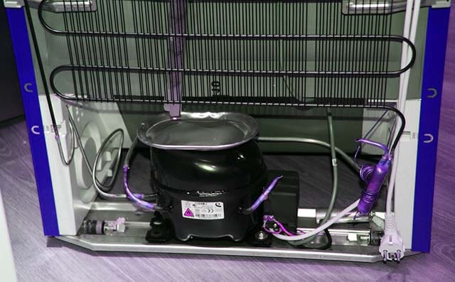
The compressor of a home refrigerator converts almost all of the consumed electricity into heat, but it works in intermittent mode
Heat input from people is determined by regulatory documents:
- 100 W / h from a person at rest;
- 130 W / h - while walking or doing light work;
- 200 W / h - during heavy physical exertion.
For calculations, the first value is taken - 0.1 kW. It remains to determine the amount of heat that penetrates from the outside through the walls by the formula:

- S - the square of the cooled room, m²;
- h is the ceiling height, m;
- q is the specific thermal characteristic referred to the volume of the room, W / m³.
The formula allows you to perform an aggregated calculation of heat flows through the outer fences of a private house or apartment using the specific characteristic q. Its values are accepted as follows:
- The room is located on the shady side of the building, the area of the windows does not exceed 2 m², q = 30 W / m³.
- With an average illumination and glazing area, a specific characteristic of 35 W / m³ is taken.
- The room is located on the sunny side or has many translucent structures, q = 40 W / m³.
Having determined the heat gain from all sources, add the numbers obtained using the first formula. Compare the results of the manual calculation with those of the online calculator.
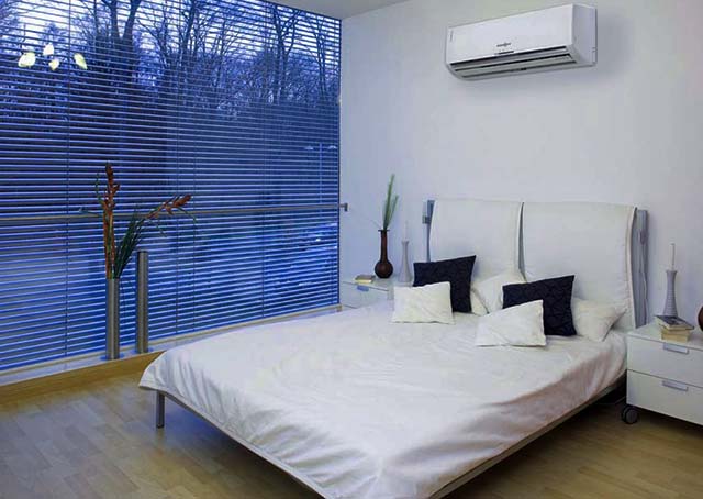
A large glazing area implies an increase in the cooling capacity of the air conditioner
When it is necessary to take into account the heat input from the ventilation air, the cooling capacity of the unit increases by 15-30%, depending on the exchange rate. When updating the air environment 1 time per hour, multiply the result of the calculation by a factor of 1.16-1.2.
Methodology for calculating the air conditioning system

Everyone can independently calculate the required power of the air conditioner using a simple formula. First of all, you need to find out what the heat flows in the room will be. To calculate them, the volume of the room should be multiplied by the heat transfer coefficient. The value of this coefficient is in the range from 35 to 40 W and depends on the orientation of the window openings. Next, it is necessary to determine what kind of thermal energy is emitted by household appliances and the energy of people who will constantly be in the room. All these values of heat gains are summed up. We increase the found number by 15-20% and obtain the required cooling capacity of the climate system.
Related articles and materials:
Design of air conditioning systemsSplit air conditioning: how to choose it?Automation of air conditioning systems
An example for a room of 20 sq. m
We will show the calculation of the capacity for air conditioning a small apartment - studio with an area of 20 m² with a ceiling height of 2.7 m. The rest of the initial data:
- illumination - medium;
- number of residents - 2;
- plasma TV panel - 1 pc .;
- computer - 1 pc .;
- refrigerator electricity consumption - 200 W;
- the frequency of air exchange without taking into account the periodically operating kitchen hood - 1.
Heat emission from residents is 2 x 0.1 = 0.2 kW, from household appliances, taking into account simultaneity - 0.3 + 0.2 = 0.5 kW, from the side of the refrigerator - 200 x 30% = 60 W = 0.06 kW. Room with average illumination, specific characteristic q = 35 W / m³. We consider the flow of heat from the walls:
Qtp = 20 x 2.7 x 35/1000 = 1.89 kW.
The final calculation of the capacity of the air conditioner looks like this:
Q = 1.89 + 0.2 + 0.56 = 2.65 kW, plus cooling consumption for ventilation 2.65 x 1.16 = 3.08 kW.
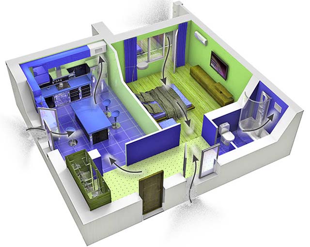
The movement of air currents around the house during the ventilation process
Important! Do not confuse general ventilation with home ventilation. The air flow coming in through open windows is too great and is altered by gusts of wind. A cooler should not and cannot normally condition a room where an uncontrolled volume of outside air flows freely.
Heat gain from solar radiation
Determination of heat gain from solar radiation is more complex and no less important. The same manual will help you with this, but if the simplest formula is used in the case of people, it is much more difficult to calculate solar heat gains. Heat gains for insolation are divided into heat flow through windows and through enclosing structures. To find them, you need to know the orientation of the building behind the cardinal points, the size of the window, the design of the enclosing elements and all other data that needs to be substituted into the expression. The calculation of heat input from solar radiation through the window is performed through the expression:
QΔt = (tout + 0.5 • θ • AMC - tp) AOC / ROC
tnar - the average daily temperature of the outside air, we take the temperature of July from SNiP 2.01.01-82
θ is a coefficient showing changes in the temperature of the outside air,
AMC - the highest daily amplitude of the outside air temperature in July, we take from SNiP 2.01.01-82
tp - air temperature in the building, we take according to SNiP 2.04.05-91
AOC, ROC - area, and the reduced resistance to heat transfer of glazing is taken from SNiP II-3-79
All data is taken from the application depending on the geographic latitude.
Solar heat gain through the building envelope is calculated as follows:

Coming from personal experience, I advise you to make a plate for calculating heat gains from solar radiation in Excel or another program, this will greatly simplify and speed up your calculations. Always try to calculate solar heat gain using this method. Sad practice shows that customers who indicate the orientation of their premises to the cardinal points are more likely an exception than a rule (Therefore, cunning designers use this cheat sheet: Heat gain from the sun for the darkened side is 30 W / m3, with normal lighting 35 W / m3, for the sunny side 40 W / m3. Take these values and multiply by the beat of the room. These calculations are very approximate, they can be several times more or less heat gains calculated by the formulas. I use this cheat sheet in rare cases: when you need to quickly pick up a conventional split system for apartments and small offices.I advise you to do your best to pull out as much data as possible and do all the same correct calculation of heat input from solar radiation.
Selecting an air conditioner by power
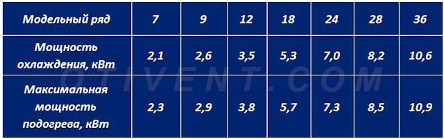
Split systems and cooling units of other types are produced in the form of model lines with products of standard performance - 2.1, 2.6, 3.5 kW and so on.Some manufacturers indicate the power of models in thousands of British Thermal Units (kBTU) - 07, 09, 12, 18, etc. Correspondence of air conditioning units, expressed in kilowatts and BTU, is shown in the table.
Reference. From the designations in kBTU went the popular names of cooling units of different cold, "nine" and others.
Knowing the required performance in kilowatts and imperial units, select a split system in accordance with the recommendations:
- The optimum power of the household air conditioner is in the range of -5 ... + 15% of the calculated value.
- It is better to give a small margin and round the result upwards - to the nearest product in the model range.
- If the calculated cooling capacity exceeds the capacity of the standard cooler by a hundredth of a kilowatt, you should not round up.
Example. The result of calculations is 2.13 kW, the first model in the series develops a cooling capacity of 2.1 kW, the second - 2.6 kW. We choose option No. 1 - a 2.1 kW air conditioner, which corresponds to 7 kBTU.
Example two. In the previous section, we calculated the performance of the unit for a studio apartment - 3.08 kW and fell between the 2.6-3.5 kW modifications. We choose a split-system with a higher capacity (3.5 kW or 12 kBTU), since the rollback to a lower one will not keep within 5%.
For reference. Please note that the power consumption of any air conditioner is three times less than its cooling capacity. The 3.5 kW unit will "pull" about 1200 W of electricity from the network in maximum mode. The reason lies in the principle of operation of the refrigerating machine - "split" does not generate cold, but transfers heat to the street.
The vast majority of climate systems are capable of operating in 2 modes - cooling and heating during the cold season. Moreover, the heat efficiency is higher, since the compressor motor, which consumes electricity, additionally heats the freon circuit. The power difference in cooling and heating mode is shown in the table above.
Rated and optimal power of the air conditioner
approximate values of various heat surpluses
The nominal power is understood as the average performance of the air conditioner for operation in the cold. But in each individual case, it is necessary to calculate the optimal power, which, ideally, should coincide as much as possible with the first.
The nominal values are selected by the manufacturers for each type of cooling device:
- Window blocks usually have the following standard positions: 5, 7, 9, 12, 18, 24;
- Wall splits correspond to the model range in this version: 7, 9, 12, 18, 24. Sometimes some brands produce non-standard models with the following nominal values: 8, 10, 13, 28, 30;
- The cassettes are in this order: 18, 24, 28, 36, 48, 60. Non-standard row: 34, 43, 50, 54;
- Channel splits start with a capacity range of 12 models and sometimes end with 200;
- Console installations have the following variety: 18, 24, 28, 36, 48, 60. In a non-standard version: 28, 34, 43, 50, 54;
- Columns start from 30 and go up to 100 or more.
This list is not accidental. It has already taken into account the selection of an air conditioner and its capacity by the area of the room, and by the height of the ceilings, and by heat inflows from household equipment, electric lighting, people, roofs with walls, open windows and ventilation.
Heat balance calculation
Recently, there has been a steady trend towards an increase in the use of frequency converters in industrial enterprises, in the field of energy, oil and gas industry, utilities, etc. This is due to the fact that the frequency regulation of the electric drive allows you to significantly save electricity and other production resources, ensures the automation of technological processes, and increases the reliability of the system as a whole. Frequency converters are used both in new projects and in the modernization of production.A wide range of capacities and various options for control systems allow you to choose a solution for almost any task.
However, with all the obvious advantages of frequency converters, they have features that, without diminishing their merits, nevertheless require additional use of special devices. These devices are input and output filters and chokes.
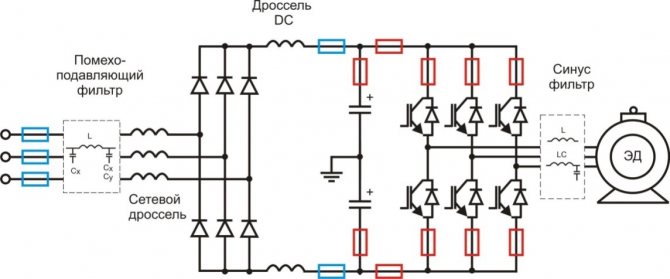
Fig. 1. The use of input and output filters in circuits with a frequency converter.
Electric drives are a well-known source of interference. Input filters are designed to minimize pickup and interference from both electronic equipment and electronic equipment, which allows you to meet the requirements for electromagnetic compatibility. The task of reducing the influence of harmonic distortions on the power grid arising during the operation of frequency converters is solved by installing line chokes in front of the frequency converters and DC chokes. FROMline choke at the input of the frequency converter also reduces the influence of phase imbalance of the supply voltage.
Output filters are used to protect insulation, reduce motor acoustic noise and high frequency electromagnetic interference in the motor cable, bearing currents and shaft voltages, thereby extending motor life and maintenance periods. Output filters include dU / dt filters and sine-wave filters.
It should be noted that sine-wave filters can be used with a switching frequency higher than the rated value, but they cannot be used if the switching frequency is more than 20% lower than the rated value. DU / dt filters can be used with a switching frequency below the rated value, but they should be avoided with a switching frequency higher than the rated value, as this will cause the filter to overheat.
Due to the fact that filters / chokes should be located as close as possible to the frequency converter, they are usually placed together with it in the same power cabinet, where the rest of the switching and control elements are also located.
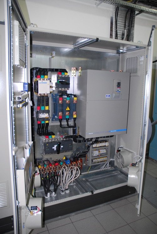
Fig. 2. Cabinet with frequency converter, filters and switching devices.
It should be understood that powerful power filters and chokes generate a significant amount of heat during operation (both the core and the winding are heated). Depending on the type of filter, losses can reach several percent of the load power. For example, a three-phase line choke SKY3TLT100-0.3 manufactured by the Czech company Skybergtech has a voltage drop of 4% in a 380 volt network, which, at an operating current of 100A, creates a power loss of 210 W. The power of the electric motor at this current will be approximately 55 kW, i.e. the absolute power loss across the choke will be small, less than 0.5%. But since this power loss is released in a closed cabinet, special measures must be taken to remove heat.
The amount of heat generated is, as a rule, proportional to the power, but also depends on the design features of the winding element. Sine-wave filters will generate more heat than, for example, dU / dt filters, since they have larger chokes and capacitors to provide more effective smoothing and high frequency suppression. The active resistance of the winding introduces significant losses. Often, in order to save money, manufacturers use a winding wire of a smaller section, sometimes made not of copper, but of aluminum. The thermogram (Fig. 3) shows 2 sine filters of the same power, but from different manufacturers. Both filters have the same power losses, but it is clearly seen that the windings of the filter on the left heat up more, and the filter on the right has a core. Naturally, other things being equal, the filter on the right will last longer than the filter on the left.overheating of the winding has a much greater effect on the durability of the filter due to an increase in leakage currents due to the appearance of microcracks in the insulation of the windings.
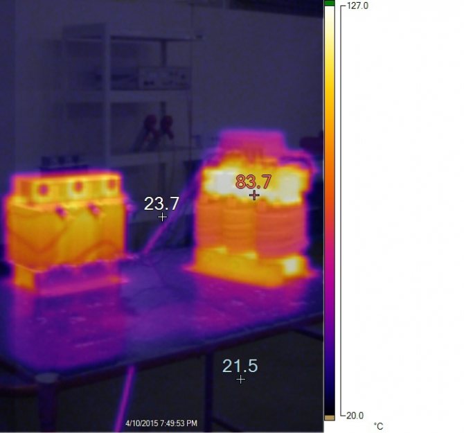
Fig. 3 Thermogram of sinusoidal filters from different manufacturers.
It should also be noted that the use of different core materials also strongly affects the power loss, that is, the heat dissipation. This is especially true in the presence of high-frequency interference in the circuit. So the Czech manufacturer Skybergtech produces two types of filters with the same parameters SKY3FSM110-400E and SKY3FSM110-400EL-Rev. A. In the second filter model, a core made of a better material is used, due to which the power loss is reduced by about 10%. It should be noted that the cost of a filter with the best thermal parameters is almost 80% higher than the cost of an analogue. Therefore, when choosing a filter, one must also pay attention to the economic factor.
Significant heating of power filters at rated power can be within the manufacturer's tolerances, but nevertheless, along with heat generation, frequency converters (FCs) must be taken into account when calculating the thermal balance of the power cabinet. Modern inverters have an efficiency of 97-98% and, as a rule, are the main source of heat in the cabinet, but not the only one. In addition to the inverter, heat is emitted by the noise suppression filter, the input choke, the motor choke or sine filter, contactors and even the cooling fan motor. Thus, it is not enough to rely only on the heat dissipation of the inverter itself in calculating the required blowing flow.
Failure to comply with the temperature regime can lead to unpleasant, and sometimes very serious consequences - from a reduction in the service life of the equipment to its fire. Therefore, maintaining the optimum temperature in the equipment cabinets is of utmost importance. There are many ways to solve this problem: using a cabinet of a different volume, using forced airflow, special heat exchangers (including using liquid cooling) and air conditioners. In this article, we will focus on the features of calculating the classic forced air cooling.
Power cabinet manufacturers have special means for calculating the thermal conditions (for example, the ProClima software from SchneiderElectric or the RittalPower Engineering software from RittalTherm). They allow to take into account the heat dissipation of all cabinet elements, including circuit breakers, contactors, etc. The cabinet design, its dimensions and placement relative to other cabinets are taken into account.
These programs have been created for calculating the thermal conditions of specific cabinets of a given manufacturer. take into account their design features, material, etc. Nevertheless, using these programs, it is quite possible to make an approximate calculation for an arbitrary cabinet, if you know certain initial parameters.
In this case, it is necessary to take into account both the sources of heat generation (power losses of the equipment) and the area of the shell (the surface of the cabinet). The data on the power losses for all built-in devices, the dimensions of the wiring closet, must be known. It is also necessary to set the values of the minimum / maximum temperature outside the cabinet, humidity and altitude (this will be needed to determine the required air flow rate). Relative humidity is used to determine the dew point, the temperature below which condensation begins to form. It is necessary to be guided by it when determining the minimum allowable temperature in the cabinet (Fig. 4).
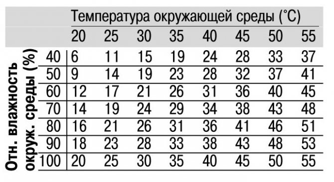
Fig. 4 Dew point determination table
The purpose of the calculation is to determine the need for forced airflow / cooling / heating, in which the internal temperature calculated from the power loss will be within the maximum / minimum permissible operating temperatures for devices in the cabinet.
Calculation of the thermal balance of a power cabinet with frequency converters consists of several stages.At the first stage, it is necessary to calculate the effective heat transfer surface area Se. The surface of the cabinet is in contact with the environment, the temperature of which is different from the temperature inside the cabinet. The effective heat exchange area Se depends on the geometric dimensions and location of the cabinet, the coefficient for each surface element is selected from the table (Fig. 5), in accordance with the IEC 60890 standard.

Figure 5: Selection table for the coefficient b to determine the effective shell area
The total effective area of the shell is:
Se =S(S0 x b)
At the second stage, the power of heat losses generated by the equipment inside the cabinet is calculated. The heat output of the cabinet is defined as the sum of the power losses of the individual elements installed in the cabinet.
Q = Q1 + Q2 + Q3….
The heat losses of individual installed equipment can be specified by their electrical characteristics. For equipment and conductors with partial load, the power loss can be determined using the following formula:
Q = Qn x (Ib / In) 2, where
Q - active power losses;
Qn - loss of rated power (at In);
Ib is the actual value of the current;
In - rated current.
Further, taking into account the known values of ambient temperatures (Temin, Temax), you can find the maximum and minimum temperatures inside the cabinet:
Ti max (° C) = Q / (K x Se) + Te max
Ti min (° C) = Q / (K x Se) + Te min, where
K is a constant that takes into account the shell material. For some common materials used for the manufacture of cabinets, it will have the following values:
K = 12 W / m2 / ° C for aluminum sheath
K = 5.5 W / m2 / ° C for painted metal sheath;
K = 3.7 W / m2 / ° C for a stainless steel sheath;
K = 3.5 W / m2 / ° C for polyester sheath.
Let's designate the required temperature values inside the cabinet as Tsmin and Tsmax.
Next, we make a decision on the choice of the necessary microclimate maintenance system:
1) If the maximum calculated temperature value exceeds the set one (Timax> Tsmax), then it is necessary to provide a forced ventilation system, heat exchanger or air conditioner; system power can be determined from the expression:
Cooling = Q - K x Se x (Ts max - Te max)
From here, the required air flow can be calculated:
V (m3 / h) = f x Pcooling / (Ts max - Te max), where
f - correction factor (factor f = Сp х ρ, product of specific heat and air density at sea level). For different altitudes above sea level, the coefficient f has the following values:
from 0 to 100 m f = 3.1
from 100 to 250 m f = 3.2
from 250 to 500 m f = 3.3
from 500 to 350 m f = 3.4
from 750 to 1000 m f = 3.5
2) If the maximum calculated temperature value is less than the specified maximum (Timax
3) If the minimum calculated temperature value is lower than the set one (Ti min
Pheating = K x Se (Tsmin - Te min) - Q
4) If the minimum calculated temperature value is higher than the set one (Ti min> Ts min), then the microclimate control system is not required.
When calculating the airflow generated by the fan, load losses caused by the exhaust components (air distribution grille and filter, presence or absence of a ventilation grill) must be taken into account.
When designing, an even distribution of power losses inside the enclosure (cabinet) should be ensured, and the location of the built-in equipment should not impede air circulation. Failure to comply with these rules will require more complex thermal calculations to eliminate the likelihood of local overheating and the bypass effect. The accessories must be sized in such a way that the effective current of the ASSEMBLY circuits does not exceed 80% of the rated current In of the devices.
Let's consider the calculation of the heat balance using a specific example.
Initial data: We have a cabinet made of painted sheet steel 2m high, 1m wide and 0.6m deep, standing in a row. The cabinet contains 2 frequency converters, two mains filters and two output sine filters, as well as switching elements, but due to their low power dissipation in relation to the specified equipment, we can neglect them. The ambient room temperature can vary from -10 to + 32 ° C. Relative humidity 70%. The admissible maximum temperature inside the cabinet is + 40 ° C. In order to avoid condensation, the minimum permissible temperature in the cabinet must be at least the dew point, i.e.in our case 26 ° C (Fig. 4)
Payment:
In accordance with the table (Fig. 5), the total effective area of the shell will be equal to:
Se =SS0 x b = 1.4 (1x0.6) +0.5 (2x0.6) +0.5 (2x0.6) +0.9 (2x1) +0.9 (2x1) = 5.64 m2
Based on the known dissipated power of individual equipment elements, we find its total value. For a frequency converter, the efficiency of which is 97-98%, we take 3% of the declared rated power for the power dissipation. Since the design takes into account that the maximum load should not exceed 80% of the nominal value, then the coefficient 0.8 is applicable for the correction of the total thermal power:
Q = 1650 × 2 + 340 × 2 + 260 × 2 = 4500x0.8 = 3600 W
Further, taking into account the known values of ambient temperatures (Te min, Te max), we find the maximum and minimum values of the temperature inside the cabinet without cooling:
Ti max (° C) = 3600 / (5.5 x5.64) + 32 = 148.05 ° C
Ti min (° C) = 3600 / (5.5 x5.64) - 10 = 106.05 ° C
Since the maximum calculated temperature value is significantly higher than the preset value (148.05 ° C> 40 ° C), it is necessary to provide forced ventilation, the power of which will be equal to:
Cooling = 3600 - 5.5 × 5.64 x (40 - 32) = 3351.84 W
Now we can calculate the required blowing performance. To take into account the load losses caused by the exhaust components (air distribution grille, filter), we will set a margin of 20%. As a result, we find that in order to maintain the temperature balance of the cabinet within the specified values, an air flow with a capacity of:
V = 3.1x 3351.84 / (40 - 32) = 1298.8x 1.2 = 1558.6 m3 / h
This air flow can be ensured by installing several fans, the air flow from which is summed up. You can use, for example, Sunon A2179HBT-TC fans. However, this should also take into account the drop in performance in the presence of resistance to flow from the installed elements of the cabinet. Taking this factor into account, in our case it will be possible to install 2 W2E208-BA20-01 EBM-PAPST fans or 4 A2179HBT-TC fans from Sunon. When choosing the number and location of the fans, it should be taken into account that their series connection increases the static pressure, and the parallel connection increases the air flow.
Forced air cooling can be realized by drawing heated air (fan installed at the outlet) from the volume of the cabinet or by blowing cold air (fan at the inlet). The choice of the required method is best done at the initial design stage. Each of these methods has its own pros and cons. Air injection allows for more efficient blowing of the hottest elements, if they are correctly located and fall into the main air stream. Increased flow turbulence increases the overall heat dissipation. In addition, the overpressure generated by the discharge prevents dust from entering the housing. In the case of exhaust ventilation, due to the reduced pressure in the volume of the cabinet, dust is drawn in through all the slots and openings. When the fan is located at the inlet, its own resource also increases, since it operates in a stream of cold inlet air. However, when the fan is placed on the exhaust side, the heat from the operation of the fan itself is immediately discharged to the outside and does not affect the operation of the equipment. In addition, due to the small vacuum created during the exhaust ventilation, air is sucked in not only through the main intake opening, but also through other auxiliary openings. Optimally positioned close to heat sources provides better flow control.
When installing fans at the inlet, it is recommended to place them in the lower part of the enclosure. An air outlet grill through which heated air is removed should be placed in the upper part of the cabinet. The air outlet grille must have the necessary degree of protection, which ensures the normal operation of the electrical installation.It should be borne in mind that installing an exhaust filter of the same size as the fan reduces the actual performance of the fan by 25-30%. Therefore, the filter outlet must be larger than the fan inlet.
When installing a fan at the outlet, they are placed in the upper part of the cabinet. The air inlets are located at the bottom and, additionally, near the sources of the most intense heat generation, which facilitates their cooling.
We add that the choice of the required blowing method remains with the designers, who, taking into account all the above factors, the required degree of IP protection and the characteristics of the equipment, must choose the most suitable one. The importance of ensuring the optimum temperature in equipment cabinets is indisputable. The given calculation methodology, based on the methods proposed by the designers of the Schnaider Electric, Rittal enclosures in accordance with IEC 60890, allows some simplifications, the use of empirical values, but at the same time allows with sufficient reliability to carry out a practical calculation of the system for maintaining the optimal thermal balance of power cabinets with frequency converters and power filters.
Authors: Ruslan Cherekbashev, Vitaly Khaimin
Literature
1. Haimin V., Bahar E. Filters and chokes of the company Skybergtech // Power electronics. 2014. No. 3.
2. IEC / TR 60890 (2014) Assemblies for low voltage switchgear. Temperature rise verification method by calculation
3. Sarel catalog. Temperature control in switchboards. www.schneider-electric.ru
4. Rules for the creation of GCC according to GOST R IEC 61439. Rittal technical library.
5. Cooling of control cabinets and processes. Rittal Technical Library 2013.
6. Vikharev L. How to work in order not to burn out at work. Or briefly about the methods and systems for cooling semiconductor devices. Part two // Power electronics. 2006. No. 1.
Calculation of the power consumed by the PC, according to the passport values of the power consumption of the nodes
When the question “How much heat does my computer generate?” Arises, we first try to find data on the heat dissipation of the nodes that are in your PC case. But such data is nowhere to be found. The maximum that we find is the currents consumed by the nodes along the power supply circuits 3.3; five; 12 V. And even then not always.
These values of consumption currents most often have peak values and are intended rather for choosing a power supply in order to exclude its overcurrent.
Since all devices inside the computer are powered by direct current, there is no problem in determining the peak (exactly peak) power consumption by your node. To do this, simply determine the sum of the powers consumed on each line, by multiplying the current and voltage consumed along the circuit (I draw your attention, no conversion factors are applied - direct current.).
Ptot = P5v + P12v = I5v * U5v + I12v * U12v
As you understand, this is a very rough estimate, which in real life is almost never performed, because all the nodes of the computer do not work at the same time in peak mode. The operating system works with PC nodes according to certain algorithms. Information is read - processed - written down - some part of it is displayed on the means of control. These operations are performed on data packets.
On the Internet, there are many estimates of precisely the value of the peak power consumption taken from the characteristics of the nodes.
The calculations that were made 2-3 years ago, in principle, do not correspond to the current situation. Because over the years, manufacturers have modernized their nodes, which has led to a decrease in their power consumption.
The latest data are shown in Table 1.
| No. pp | Knot | Power consumption per node, W | Explanations |
| 1 | Processor (CPU) | 42 — 135 | More precisely, see the specification of your processor |
| 2 | Motherboard | 15 — 100 | More precisely, see.publications or do the calculation yourself (depending on its specification) |
| 3 | Video card | Up to 65 | Bus powered, see documentation for details |
| Up to 140 | With separate power supply, more precisely see the documentation | ||
| 4 | RAM | 3 — 15 | Depends on capacity and operating frequency, more precisely, see the documentation |
| 5 | Hard disk, HDD | 10 — 45 | Depends on the operating mode, more precisely, see the specification |
| 6 | CD / DVD - RW | 10 – 30 | Depends on the operating mode, more precisely, see the specification |
| 7 | FDD | 5 – 10 | Depends on the operating mode, more precisely, see the specification |
| 8 | Sound card | 3 — 10 | Depends on the operating mode, more precisely, see the specification |
| 9 | Fan | 1 — 4,5 | More precisely, see the specification |
| 10 | Network card / built-in | 3 — 5 | More precisely, see the specification |
| 11 | USB 2 / USB 3 port | 2.5 / 5 (according to some reports more than 10 W per USB3 port) | To the connected port |
| 12 | COM, LPT, GAME ports | < 2 | For each connected port |
| 13 | Built-in sound card | < 5 | When using passive speakers |
| 14 | Power Supply | P cons. max + 30% | Selected after calculating consumption |
Table 1.
We see the data have a very wide scatter, it is determined by the specific model of your node. Nodes of different manufacturers, especially those produced at different times, have a wide range of power consumption. In principle, you can do the calculation yourself.
The calculation of the power consumed by the PC is carried out in several stages.
It:
- Collecting information about the power consumed by the node,
- Calculation of total power consumption and selection of PSU,
- Calculation of the total consumption of the PC (taking into account the power supply).
An integral part of the heat dissipation calculation is the calculation of the power consumed by the computer. From which the power of the power supply is determined, a specific model is selected, after which its heat dissipation is estimated. Therefore, when performing a thermal calculation, it is necessary to first collect data on the power consumed by the computer nodes.
But so far, even the power consumption is not always given by the manufacturers of computer components, sometimes the value of the supply voltage and the current consumption for this voltage is indicated on the parameter plate. As mentioned above, at direct current, which is used to power the computer's nodes, the product of the supply voltage and the current consumed at a given voltage indicates the power consumption.
Based on the total power consumption (taking it as the heat dissipation power), it is possible to perform a preliminary or approximate calculation of the cooling system. This calculation will rather provide excessive cooling of your PC, which in conditions of high load and, accordingly, maximum heat release gives some approximation to the real heat release and will provide normal cooling. But when the PC is used for ordinary (not resource-intensive) applications, the cooling system calculated in this way is clearly redundant, and ensuring the normal functioning of the PC nodes creates inconvenience to the user due to the increased noise level.
First of all, you should know that the power consumption and heat dissipation of the nodes are directly related.
The heat dissipation power of electronic components is not equal to the power consumption, but they are related to each other through the power loss factor of the unit.
There are many publications on how to perform this calculation, there are special sites on the Internet for this calculation. But still there are questions about its implementation.
Why?
And because not only the heat dissipation power is difficult to find from the manufacturer, but even the power consumed by the node we are interested in is not always known. Perhaps they are simply afraid to cite them due to the fact that their value is not unstable during operation and depends significantly on the operating mode. The difference can be up to ten times and sometimes even more.
They don't seem to want to overwhelm users with "unnecessary" information. And I haven’t found any data for manufacturers yet.
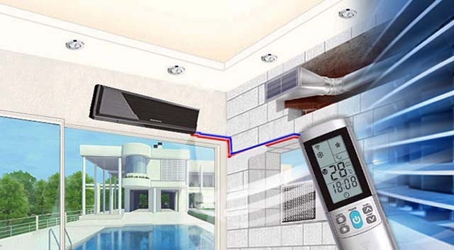
Recommendations for choosing the type of air conditioner
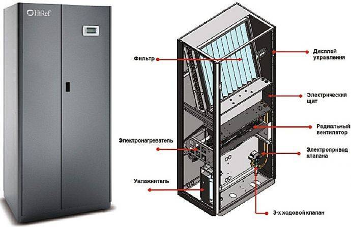
Server cabinet air conditioner
Difficult operating conditions with continuous load are not able to withstand every climate system. It must be equipped with a dust filter, dehumidifier, winter kit. One of the options for air cooling is an air-conditioned server cabinet. The design does not require condensate drainage, the outdoor unit is compact in size. The indoor unit is installed vertically or horizontally inside a server cabinet.
Requirements for air conditioners
When maintaining the climate in the server rooms, the smooth operation of air conditioners is important. Breakdown and repairs will leave telecommunications equipment uncooled for a long time. The principle of rotation and reservation allows the requirement to be met. Several climate control units are installed in the room, connected into one network by a rotary device. In the event of a malfunction of one air conditioner, the backup option is automatically activated.
The alternating switching on of the blocks allows you to balance the load and ensure optimal climate parameters. In this mode, the technician stops alternately for rest and maintenance.
The rotation unit helps to control the air conditioning of the server rooms. It automatically alternates the switching on of working units, if necessary, connects a backup device. The second control option is the installation of sensors, the readings of which are displayed on the computer monitor. You don't have to leave your workplace to determine the conditions in the server room. All information in the form of tables and graphs goes to the computer. Messages are accompanied by a sound signal.
Split systems
Column air conditioner device diagram
To maintain the specified parameters in the server rooms, split systems are used. Household or semi-industrial high-power systems are installed in small rooms with a heat release of up to 10 kW. By the type of installation, they are:
- Wall mounted - a versatile and affordable option. Productivity is 2.5-5 kW, a model is selected in which a significant length of the freon line is provided. Recommended manufacturers are Daikin, Toshiba and Mitsubishi Electric.
- Ducted - devices are placed under a false ceiling, save space and provide effective air exchange. Suitable for large server rooms. Ducted air conditioning supplies cold air directly to the racks.
- Column - powerful systems in the form of cabinets are installed on the floor, do not require installation.
Precision climate systems
Server room precision air conditioners are professional equipment. Climatic complexes have a high resource of continuous operation, allow maintaining optimal temperature and humidity parameters. One of the advantages of the equipment is accuracy, climatic indicators in large premises have fluctuations of no more than 1 ° C and 2%. In server rooms, cabinet and ceiling models are installed. The first are distinguished by their bulky dimensions, their power is 100 kW. Ceiling systems are less efficient (20 kW) and are installed in rooms where it is not possible to place cabinet air conditioners.
Types of precision climatic devices
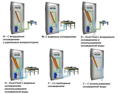
Climatic complexes can be monoblock and separate according to the type of split systems. The system is cooled in various ways: by evaporation of freon, water or air circuit. Popular manufacturers: UNIFLAIR, Blue box.
Pluses of installations:
- uninterrupted work;
- high power of equipment;
- precise control of climatic components;
- wide range of operating temperatures;
- compatibility with dispatch control.
Cons of precision systems:
- high price;
- noisy monoblock design.
Chiller fan coil system
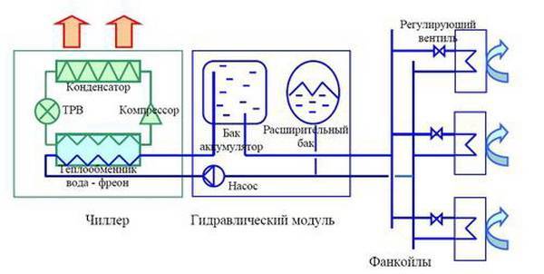
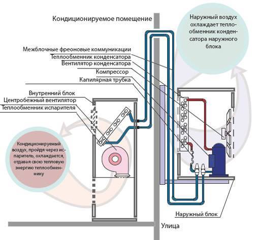
The air conditioning system uses water or an ethylene glycol mixture as the heating medium. The principle of operation is similar to installations with freon.The chiller cools the liquid circulating in the fan coil heat exchanger, and the air passing through the radiator lowers the temperature.
- high performance;
- versatility;
- safe and affordable operation.