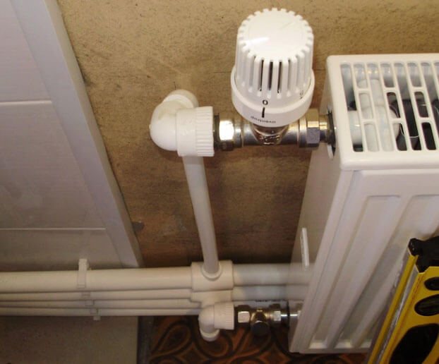
Control valve functions
Control valves are used in the piping of the heating system
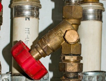
According to the generally accepted classification, a control valve for heating refers to the elements of shut-off valves included in the piping of the system. Its main purpose is to open and close the channel for the coolant to pass directly through the batteries. Modern requirements for the arrangement of the piping prescribe the mandatory equipping of heating systems with locking elements of various types.
Their presence makes it possible to shut off the movement of the coolant in an accident and perform troubleshooting operations without removing the liquid from the pipes. In addition, due to the limitation of the volume of the circulating medium, it is possible to maintain a comfortable temperature distribution in a private house or apartment.
Regardless of the type of heating system, the ability to control heat flows allows you to reduce fluid consumption and balance the pressure distribution in it. In addition, adjusting elements are used in special devices responsible for maintaining a fixed temperature level.
Hot water heating problems
We wrote earlier that a good heating system is quite expensive. Now let's talk about why these costs are not always justified. For example, a system that worked perfectly all winter suddenly starts to malfunction with the arrival of spring. This article will focus on the hydraulic adjustment of heating systems and how to make it feasible, even for a layman.
Balancing is a necessity or an overkill?
Measuring and computing devices Any heating system must be hydraulically adjusted before delivery to the customer. This job requires a certain level of skill and is somewhat similar to tuning a piano. Step by step, the master adjusts the heating devices (radiators) and the risers of the system until he achieves their coordinated interaction.
Hydraulic adjustment of the heating system is the redistribution of the heat carrier (water) over the closed sections of the system (experts say "along the circulation circuits") so that the volume (or "flow rate") of water flows through each radiator and through each circuit is not less than the calculated one. Experts often refer to this process as “balancing,” “aligning,” or “tuning”.
In order for the system to reliably provide complete comfort in the house, it must be carefully balanced in all its components: the boiler, the radiator network and the control circuit. And the more complex the system, the more accurate and more laborious balancing it requires.
Currently, the balancing problem is complicated by two circumstances. The first is the lack of experienced craftsmen for numerous construction and service firms. The second is the constant complication of heating systems, their saturation with elements of complex automation, which builders have to master along the way.
It would seem that it is these devices that should automatically ensure the balance of the parts of the system. Nothing like this! Automation can only work normally in a hydraulically balanced system, and not vice versa. Moreover, the system must not only be balanced, but adjusted to the optimal parameters so as not to overload the automation, to create the best working conditions for it.
This work is performed in the form of a certain chain of simple regulatory actions using special balancing and measuring devices.On the market, such devices are offered by the following companies: TAHYDRONICS (Sweden), OVENTROP, HEIMEIER (Germany), HERZ (Austria), CRANE (England), DANFOSS, BROEN (Denmark). What's new they bring to the balancing technology, which was previously only possible for experienced craftsmen.
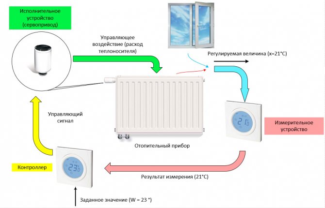
What thermostats can't handle
To "tame" the heating system, you need to understand how, in each specific case, to use to your advantage the two basic laws of hydraulics, which obey the flow of water in the system. The first of them says that water flows primarily to where there is less hydraulic resistance to its movement. The essence of the second can be expressed as follows: “Overflow in one area means that there is underfilling on the other”. Therefore, to control the flow of the coolant along the circuits of the system, different control valves are used.
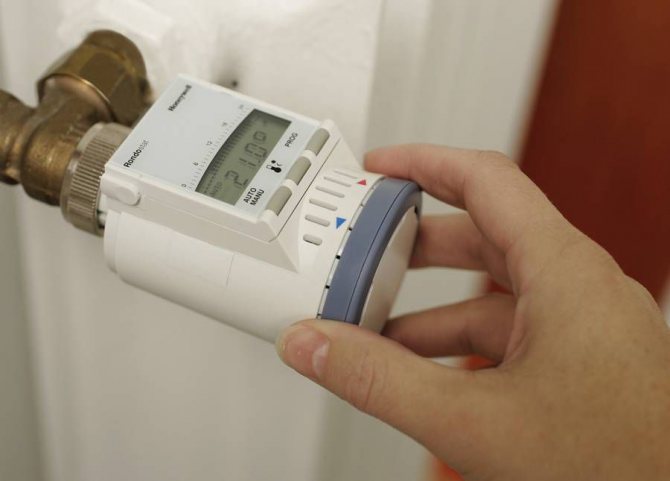
In modern systems, thermostatic valves are most often used for this, which automatically regulate the flow of water in accordance with the readings of a temperature sensor. Through the efforts of advertising, in the minds of customers and, unfortunately, many builders-practitioners, the erroneous idea has been strengthened that thermostats and other "bells and whistles" in the form of programmers, etc., installed on radiators, will themselves provide the necessary water distribution and thereby create a sufficient comfort in the home, which makes complete balancing of the system unnecessary. All this is far from the case!
In practice, the matter is complicated by the fact that the actual resistance of the circuits, the parameters of pipes, fittings and devices installed in the system rarely coincide with the calculated ones. During installation, it is possible to change the length of pipes, bending radii, reduce the flow area of pipes during welding or when laying under a screed, etc. Affects the flow distribution and gravitational pressure of water, which depends on its temperature and the height of the radiators.
The thermostats are not able to compensate for the influence of all deviations from the design and ensure complete balancing of the system. Why is that? The principle of operation of the thermostat can be easily explained using the model of the well-known water level regulator in the toilet cistern. Only the water level in it should be considered as the level of the room temperature, the drain flow - as heat loss from the room, and the inflowed flow means the heat release from the radiator. When the level decreases, the float raises the valve sealing cone in proportion to the decrease in the level. Equilibrium occurs when the heat loss from the room is equal to the heat dissipation of the radiator.
If there is no heat loss (for example, in spring), then the level rises and the valve closes (level H3). When the heat loss is greatest (in winter), the valve is fully open (H0 level). Indeed, in the spring, when the consumption of heat, and therefore hot water is small, the thermostat must be covered. In this case, to maintain the usual temperature control accuracy of 0.5C, the thermostat control valve must be moved with an accuracy of about five micrometers, which is practically difficult to do. Therefore, the main control of the heat transfer of radiators is usually carried out by varying the temperature of the water supplied to the radiator in various ways as the air temperature changes. Thermostats are used to regulate the room temperature with an accuracy of 0.5C relative to a given level. In this case, the flow rate through the thermostat is set with an accuracy of 10-15%, which is not suitable for high-quality balancing.
The difficulty of balancing is caused by the fact that the circulation circuits mutually influence each other (theorists say "they are interactive"). This means that when, for example, the flow rate in a circuit decreases with the help of a valve, the pressure drop applied to other circuits, and hence the flow through them, increases, and vice versa. Because of this, in systems, even those equipped with complex automation, but regulated only with the help of thermostats (a common option), a variety of troubles can arise.For example, the problem of "morning start" after the night heating mode at a lower temperature. In such a system, some thermostats will open more when balancing, others less. In the morning, after the command from the program block: "Increase the temperature to ...!", All thermostats are fully opened. Then, through the radiator (circuit) with the least "clamped" thermostat, the flow rate will increase more than that of others (after all, it has the lowest resistance). It means that some radiator will not receive the required flow rate (the "operelive" law is triggered). Moreover, an increase in the flow through an "overfilled" radiator, say, will double its heat transfer by only 7-12%. This means that its valve will not close to the setting level very soon. All this time, the "underfilled" radiator will heat up the room badly. Thermostats with the so-called “saturated” flow characteristic (for two-pipe systems) help to cope with such a nuisance. those in which the lift of the valve to full opening only slightly increases the flow through it in excess of the nominal. Similar thermostats are available from HEIMEIER, TA and OVENTROP.
Further. In warm weather (for example, in spring), all thermostats are covered even more, and some are forced to work, being very much covered. The risk of clogging of such thermostats is very high given our water quality. At the same time, changes in room temperature by the same 0.5C cause large changes in the inflowing flow. They, in turn, change the temperature in the room by more than 0.5C, and the operation of such a thermostat becomes unstable, that is, the temperature in the room begins to fluctuate (what kind of comfort is there).
Another possible nuisance is the noise (whistling) in the valves. Any excess external heat, for example, the winter sun in the windows, a large number of guests, etc., leads to the fact that the heavily covered thermostats are covered even more, almost completely. It is here that whistling can occur in them (and even intensify in the radiators). In addition, in systems where the circuits have other pumps with a higher capacity than the boiler pump, excess flow in a circuit can lead to the formation of a "parasitic" mixing point of water from the boiler and return water from the circuit. This point will act as a "plug" in the way of heat transfer from the boiler to the system and fuel costs will be ineffective.
Are all these misfortunes inevitable? Of course not. It all depends on the actual hydraulic parameters of the system. But the likelihood of these problems in partially or poorly balanced systems is high. So, in order to guarantee the flow of the coolant through the devices even in the most severe cold and not languish from the heat in spring, it is recommended to introduce balancing valves (valves) and even flow, pressure and bypass valves in different combinations into the system, in addition to thermostats. the complexity of the system. They extinguish the excess pressure drop, which is harmful for the operation of the thermostats, and then the latter work in the best conditions for them and with the greatest efficiency. Moreover, the maintenance of such systems is simplified, since the reasons for the disruption of its work disappear. Malfunctions that arise are easily detected and eliminated without causing long-term inconvenience to residents.
Different systems require different balancing valves. In general, the accuracy of flow control during balancing should be at least 7%. Balancing valves from TA, OVENTROP and HERZ ensure this accuracy.
Balancing valves cost $ 25-65, and a pressure or flow regulator is $ 120-140, depending on size and firm.
Is it possible to do without them? In modern city houses with very extensive heating systems, this is practically impossible, in cottages, yes, it is possible.But the quality of comfort provision will deteriorate significantly. The more complex the system or the more deviations from the design (the worse the installation quality), the higher the need to install balancing devices in it.
Balancing of one-pipe, two-pipe associated and hot water supply systems has its own characteristics, which should be discussed separately.
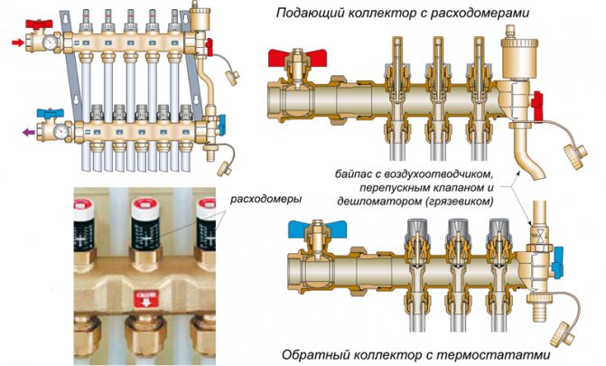
Balancing devices
Sectional balancing valveBalancing valves
are two-way valves with variable bore and with additional taps before and after the bore. At these taps, the pressure drop across the valve can be measured, and from it the water flow rate can be determined. To do this, use special graphs, nomograms, various types of slide rule or electronic measuring devices.
Pressure regulators
are proportional regulators with smooth pressure regulation from 5 to 50 kPa. They are used in complex systems and installed in the return pipeline. They maintain the setpoint differential pressure across the thermostats.
Flow regulators
automatically limit the flow rate to the set value in the general range of 40-1500 l / h, maintaining the pressure drop across the valve at the level of 10-15 kPa.
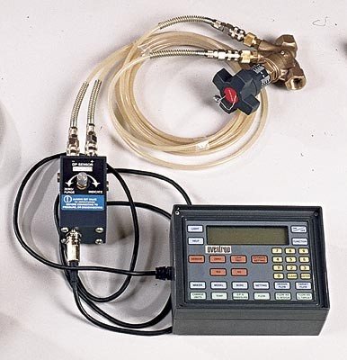
Electronic measuring and computing devices (IVP)
different firms supply with approximately the same set of basic functions. In addition to measuring flow rates and differential pressures across control valves, they allow you to determine settings for different types of valves, as well as perform system calculations. They are expensive, up to $ 3500, but for firms specializing in installation and commissioning and service maintenance, this is a very useful thing, because greatly reduces labor costs for design, balancing and subsequent maintenance of systems. So, 2 people in 2-3 hours balance the system of 5-6 stands with 30-40 radiators. Appribor can be rented from dealers.
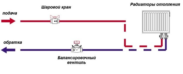
Balancing technique
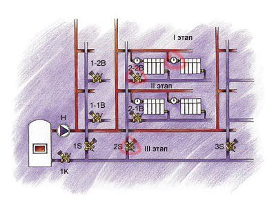
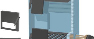
General diagram of a heating system using balancing valves The entire system is divided into separate parts (modules), so that the flow in them can be regulated by one balancing valve installed at the outlet of each module. Such a module can be a separate radiator (this is the best, but expensive option), a group of room radiators, a whole branch or riser with all its branches (or even an entire building with central heating). What does it do? Firstly, any changes in the operation of elements inside the module, for example, turning off one radiator, will practically not affect the operation of other modules. Secondly, any changes in flow or pressure outside the module do not change the proportions of flow through its elements. It turns out that the modules can be balanced in relation to each other. Further. Each module can be part of a larger module (like a nesting doll). Therefore, after balancing the radiators of the branch, for example, by adjusting the thermostats, this branch can be considered as a kind of module with its own balancing valve installed at the outlet of this branch. Then the modules, consisting of branches, are balanced against each other using a common valve installed on the riser. Each riser with all its branches is considered as an even larger module. So the modules (from the risers) are again balanced with each other using their balancing valve installed on the return main line. Practice has shown that the best results are obtained when the pressure loss across the balancing valve of the "clamped" module is 3-4 kPa.
Such valves are mounted in such a way that the straight section of the pipe before and after it is not shorter than five pipe diameters, otherwise the turbulence of the flow significantly reduces the control accuracy.
Preparatory work.
The essence of these works is to carefully plan the entire process. According to the project, the calculated flow rates for all heat consumers are specified, and if other radiators were purchased, then the flow rates through them must be corrected. All valves and taps are opened. Check the correct operation of the pumps. The system is thoroughly rinsed, filled with deaerated water and deaerated. Warm up the system to the design temperature and remove air again.
Balancing compensation method
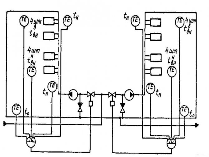
There are two methods of balancing using balancing valves: proportional and compensating. The latter is developed on the basis of the former and is used more often, because With this, the system can be balanced and put into operation in parts, without rebalancing these parts after the installation of the entire system is completed. When carrying out work in winter, this is a very significant advantage. For two-pipe systems with radiators equipped only with thermostats, balancing using the IVP device is carried out as follows. For clarification, we will have to refer to the layout of risers, branches and radiators of an imaginary heating system.
We select the "coldest" or remote riser, for example, riser 2S, and on it, the most distant branch. Let it be a branch of the second floor. Let's call it "reference". We set the calculated adjustment values on the thermostat heads (per project). We determine with the help of the device (but also according to the nomogram) the reading of the valve setting scale 2-2B, at which the flow through this valve will be equal to the total flow through branch 2, and the pressure drop across the valve will be 3 kPa. We adjust the valve 2-2B to this scale value. We connect the IVP device to the 2-2V valve. Then, by adjusting the valve of the riser 2S, we achieve the value p = 3kPa on the valve 2-2B. This means that the calculated water flow now passes through the "reference" branch.
Then we regulate the radiators of branch 1 in the same way, only we “twist” its balancing valve 2-1B according to the prompts of the IVP device until the device connected to it shows the calculated flow rate for this branch. We check the value of p on the valve 2-2B of the "reference" branch. If it has changed, then with the 2S valve we bring it to the value p = 3kPa. Then we do the same on the other branches, in turn, each time adjusting the value of p on the valve 2-2B of the "reference" branch to a value of p = 3 kPa. Having finished balancing one riser, go to another and do everything in the same way, considering riser2 as a "reference". On its 2S valve, we set the calculated flow rate and then, when we adjust other risers, we constantly maintain it for this riser using a common 1K valve on the return line. After balancing all risers, the p value measured at the last 1K valve will show the excessive pressure developed by the pump. By reducing this surplus (by adjusting or changing the pump), we will reduce the heat consumption for heating the street. You see how simple and formalized everything is to the limit. Follow the directions and the quality of the system is assured.
In our photo reportage, we briefly talked about balancing a two-pipe system with two risers equipped with balancing valves from OVENTROP.
The editors would like to thank OVENTROP for their help in organizing photography and TAHydronics for the materials provided.
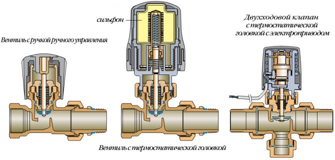
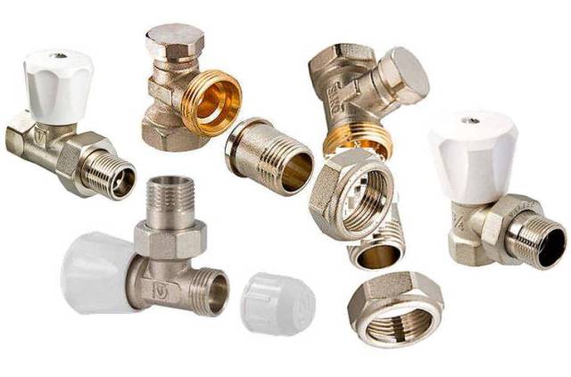
Types of control valves and their parameters
The types of special valves for controlling the supply of heat to the radiator include:
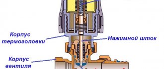
- regulators made in the form of valve mechanisms with thermal heads, setting a fixed temperature;
- ball valves;
- special balancing valves, manually controlled and installed in private houses - with their help it is possible to evenly heat the interior of the house;
- bleed air valves - Mayevsky's manual mechanisms and more advanced automatic air vents.
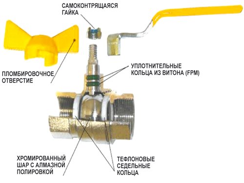
Ball
With thermal head
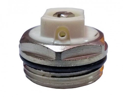
Mayevsky crane
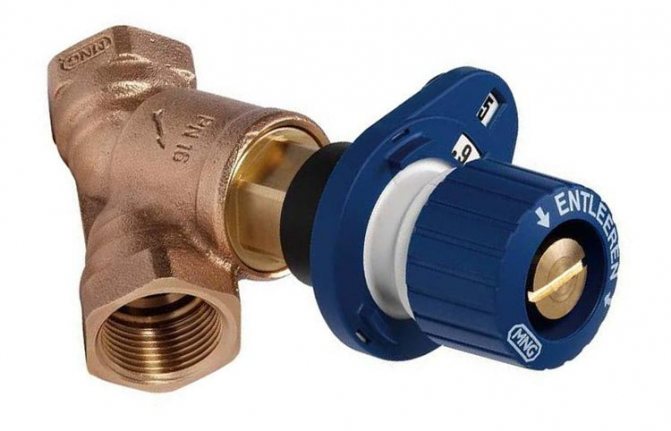
Balancing
The list is supplemented by sample valve regulators used for flushing batteries and draining water. The same class also includes a check valve that prevents the movement of the coolant in the opposite direction in networks with forced circulation.
The indicators characterizing the operation of any type of shut-off valves include:
- standard sizes of devices by which they are matched to specific types of radiators;
- pressure maintained in operating modes;
- limiting temperature of the carrier;
- product throughput.
For the correct choice of the shut-off valve, it will be necessary to take into account all the parameters in total.
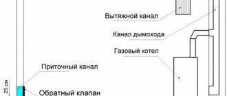
How to create and add pressure to the heating system
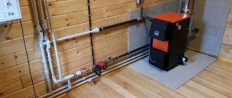
To create or add pressure in the heating system, several methods are used.
Crimping
Pressure testing - the process of initial filling of the heating system a coolant with a temporary creation of a pressure exceeding the working one.
Attention! For new systems, during commissioning, the head must be 2-3 times more normal, and during routine checks, an increase in by 20-40%.
This operation can be performed in two ways:
- Connecting the heating circuit to the water supply pipe and gradual filling of the system to the required values with pressure gauge control. This method will not work if the pressure in the water supply system is not high enough.
- Use of hand or electric pumps. When there is already a coolant in the circuit, but there is not enough pressure, special pressure pumps are used. The liquid is poured into the reservoir of the pump, and the head is brought to the required level.
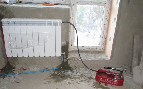
Photo 1. The process of crimping the heating system. In this case, a manual pressure test pump is used.
Checking the heating main for leaks and leaks
The main purpose of pressure testing is to identify faulty elements of the heating system in the maximum operating mode in order to avoid accidents during further operation. Therefore, the next step after this procedure is to check all elements for leaks. The tightness control is carried out by the drop in pressure within a certain time after pressure testing. The operation consists of two stages:
- Cold check, during which the circuit is filled with cold water. Within half an hour, the pressure level should not drop more than by 0.06 MPa. In 120 minutes the fall should be no more than 0.02 MPa.
- Hot check, the same procedure is carried out, only with hot water.
According to the results of the fall, conclusion about the tightness of the heating system... If the check is passed, the pressure level in the pipeline is reset to operating values by removing excess coolant.
The principle of operation of heating taps
The use of shut-off valves in the heating system
It is more convenient to consider the principle of operation of the crane using the example of a ball valve. To control it, it is enough to turn the lamb by hand. The essence of such a mechanism is as follows:
- When the crane handle is mechanically turned, the impulse is transmitted to the shut-off element made in the form of a ball with a hole in the middle.
- Due to the smooth rotation, an obstacle appears or disappears in the path of the fluid flow.
- It either completely blocks the existing passage, or opens it for the free passage of the coolant.
It is not possible to regulate the volumes of liquid entering the batteries using a ball valve.
A valve that allows you to do this, in its principle of operation, differs markedly from a spherical analogue. Its internal structure allows for smooth closing of the passage opening in a few turns. Immediately after changing the balancing, the valve position is fixed in order not to accidentally violate the device settings. As a rule, such taps are installed on the radiator outlet pipe.
The assortment of valve products includes samples with extended functionality, which allow for additional possibilities for adjusting the coolant flow.
Main menu
Hello, friends! This article was written by me in co-authorship with Alexander Fokin, head of the marketing department of Teplocontrol OJSC, Safonovo, Smolensk region. Alexander is well acquainted with the design and operation of pressure regulators in the heating system.
In one of the most common schemes for heating points of a building - dependent, with elevator mixing, pressure regulators of direct action RD "after themselves" serve to create the necessary pressure in front of the elevator. Let's consider a little what a direct-acting pressure regulator is. First of all, it must be said that direct-acting pressure regulators do not require additional energy sources, and this is their undoubted advantage and advantage.
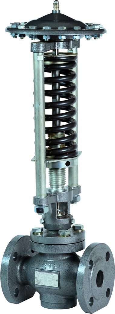
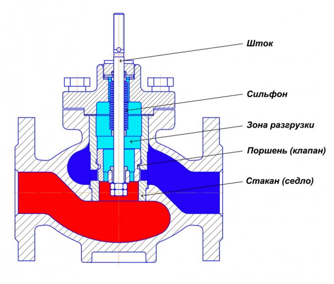
The principle of operation of the pressure regulator consists in balancing the pressure of the setting spring and the pressure of the heating medium transferred through the diaphragm (soft diaphragm). The diaphragm receives pressure impulses from both sides and compares their difference with the preset one, set by the appropriate compression of the spring with the adjusting nut.
An automatically maintained differential pressure corresponds to each speed. A distinctive feature of the membrane in the pressure regulator after itself is that on both sides of the membrane, not two impulses of the coolant pressure act, as in the differential pressure (flow) regulator, but one, and atmospheric pressure is present on the other side of the membrane.
The pressure impulse of the RD "after itself" is taken at the outlet from the valve in the direction of movement of the coolant, maintaining the specified pressure constant at the point of taking this impulse.
With an increase in pressure at the entrance to the taxiway, it is covered, protecting the system from overpressure. The setting of the RD to the required pressure is carried out with the adjustment nut.
Let's consider a specific case. At the entrance to the ITP, the pressure is 8 kgf / cm2, the temperature graph is 150/70 ° C, and we have previously made the calculation of the elevator and calculated the minimum required available head in front of the elevator, this figure turned out to be 2 kgf / cm2. The available head is the pressure difference between the supply and return upstream of the elevator.
For a temperature graph of 150/70 ° C, the minimum required available head, as a rule, as a result of the calculation, is 1.8-2.4 kgf / cm2, and for a temperature graph of 130/70 ° C, the minimum required available head is usually 1.4- 1.7 kgf / cm2. Let me remind you that the figure turned out to be 2 kgf / cm2, and the graph is 150/70 ° С. Return pressure - 4 kgf / cm2.
Therefore, in order to achieve the required available pressure calculated by us, the pressure in front of the elevator should be 6 kgf / cm2. And at the input to the heat point, the pressure we have, I remind you, is 8 kgf / cm2. This means that the RD should work in such a way as to relieve the pressure from 8 to 6 kgf / cm2, and keep it constant "after itself" equal to 6 kgf / cm2.
We come to the main topic of the article - how to choose a pressure regulator for a given case. Let me explain right away that the pressure regulator is chosen according to its throughput. The throughput is designated as Kv, less commonly the designation KN. The throughput Kv is calculated by the formula: Kv = G / √∆P. Throughput can be understood as the ability of the taxiway to pass the required amount of coolant in the presence of the required constant pressure drop.
In the technical literature, the concept of Kvs is also found - this is the flow capacity of the valve in the maximum open position. In practice, I often observed and observe, the taxiway is selected and then purchased according to the diameter of the pipeline. This is not entirely true.
Let's make our calculation further. The figure for the flow rate G, m3 / hour is easy to obtain. It is calculated from the formula G = Q / ((t1-t2) * 0.001).We necessarily have the required figure Q in the heat supply contract. Let's take Q = 0.98 Gcal / hour. The temperature graph is 150/70 C, therefore t = 150, t2 = 70 ° C. As a result of the calculation, we get a figure of 12.25 m3 / hour. Now it is necessary to determine the differential pressure ∆P. What does this number mean in general? This is the difference between the pressure at the inlet to the heat point (in our case, 8 kgf / cm2) and the required pressure after the regulator (in our case, 6 kgf / cm2).
We make a calculation. Kv = 12.25 / √ (8-6) = 8.67 m3 / h. In the technical and methodological manuals, it is recommended to multiply this figure by another 1.2. After multiplying by 1.2 we get 10.404 m3 / h.
So, we have the capacity of the valve. What should be done next? Next, you need to determine the RD of which company you will purchase, and look at the technical data. Let's say you decide to purchase RD-NO from Teplocontrol OJSC. We go to the company's website https://www.tcontrol.ru/, find the required RD-NO regulator, look at its technical characteristics.
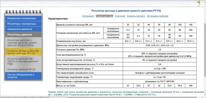
We see that for a diameter of dy 32 mm, the throughput is 10 m3 / h, and for a diameter of du 40 mm, the throughput is 16 m3 / hour. In our case, Kv = 10.404, and therefore, since it is recommended to choose the nearest larger diameter, then we choose - dy 40 mm. This completes the calculation and selection of the pressure regulator.
Next, I asked Alexander Fokin to tell us about the technical characteristics of pressure regulators RD NO JSC "Teplocontrol" in the heating system.
With regards to, RD-NO of our production. Indeed, there used to be a problem with membranes: the quality of Russian rubber left much to be desired. But for 2 and a half years now we have been making membranes from the material of the EFBE company (France) - the world leader in the production of rubber-woven membrane cloths. As soon as the material of the membranes was replaced, complaints about their rupture practically ceased.
At the same time, I would like to note one of the nuances of the design of the membrane assembly at RD-NO. Unlike the Russian and foreign counterparts on the market, the RD-NO membrane is not molded, but flat, which allows it to be replaced with any piece of rubber with a similar elasticity (from a car tube, conveyor belt, etc.) when it breaks.
As a rule, it is necessary to order the “native” diaphragm from pressure regulators of other manufacturers, as a rule. Although it is honestly worth saying that membrane rupture, especially when working on water with temperatures up to 130 ° C, is a disease, as a rule, of domestic regulators. Foreign manufacturers initially use highly reliable materials in the manufacture of the membrane.
Oil seals.
Initially, the design of the RD-NO had a stuffing box seal, which was a spring-loaded fluoroplastic cuffs (3-4 pieces). Despite all the simplicity and reliability of the design, periodically they had to be tightened with the gland nut to prevent leakage of the medium.
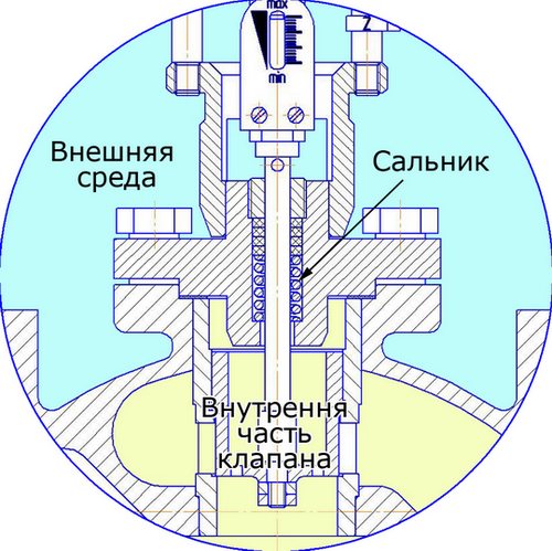
In general, based on experience, any stuffing box packing has a tendency to loss of tightness: fluorine rubber (EPDM), fluoroplastic, polytetrafluoroethylene (PTFE), thermally expanded graphite - or due to the ingress of mechanical particles into the stuffing box area, from a "clumsy assembly", insufficient purity of stem processing , thermal expansion of parts, etc. Everything flows: Danfoss (whatever they say), and Samson with LDM (although this is an exception here), I generally keep quiet about domestic control valves. The only question is when it will flow: during the first months of operation or in the future.
Therefore, we made the strategic decision to ditch the traditional packing gland and replace it with a bellows. Those. use the so-called "bellows seal", which gives absolute tightness of the stuffing box. Those. the tightness of the stuffing box now does not depend on temperature changes, or on the ingress of mechanical particles into the area of the stem, etc.- it depends exclusively on the resource and the cyclic durability of the bellows used. Additionally, in case of failure of the bellows, a back-up PTFE sealing ring is provided.
For the first time, we applied this solution on pressure regulators RDPD, and from the end of 2013 we began to produce the modernized RD-NO. In doing so, we managed to fit the bellows into the existing housings. Usually the biggest (and in fact the only drawback) of bellows valves is the increased overall dimensions.
Although, we believe that the applied bellows are not completely suitable for solving these problems: we think that their resource will not be enough for all the prescribed 10 years of operation of the regulator (which are indicated in the GOST). Therefore, now we are trying to replace the used tubular bellows with new membrane ones (few people use them yet), which have several times longer resource, smaller dimensions with greater "elasticity", etc. But so far, for the year of production of bellows-type RD-NO and for 4 years of production of RDPD, there has not been a single complaint about rupture of the bellows and leakage of the medium.
I would also like to note the unloaded cell design of the RD-NO valve. Thanks to this design, it has an almost perfect linear response. And also the impossibility of the valve skewing as a result of the ingress of any trash floating in the pipes.
Installation and adjustment of valves
A balancing valve is installed to regulate the flow of the coolant on the way to the boiler
When installing non-adjustable ball valves, simple schemes are used that allow them to be freely placed on polypropylene branches from the riser even before they enter the batteries. Due to the simplicity of the design, the installation of these products is possible on our own. Such shut-off valves do not need additional adjustment.
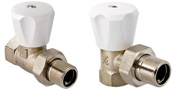
It is much more difficult to mount valve devices at the outlet of heating batteries, where flow volume adjustment is required. Instead of a ball valve, in this case, a control valve is installed for heating, the installation of which will require the help of specialists. You can do this on your own only after carefully studying the installation instructions.
Depending on the layout of the devices and the distribution of heating pipes, it is possible to select a special angular valve suitable for radiators with a decorative coating. When choosing a product, attention is paid to the value of the limiting pressure, usually indicated on the case or in the product passport. With a small error, it should correspond to the pressure developed in the heating network of a multi-storey residential building.
It is advisable to adhere to the following recommendations:
- For installation on radiators, you should select high-quality taps made of thick-walled brass, forming a connection with a union nut - American. Its presence will allow, if necessary, to quickly disconnect the emergency line without unnecessary rotational operations.
- On a single-pipe riser, a bypass will need to be installed, installed with a slight offset from the main pipe.
It is even more difficult to solve the issue of installing a balancing type valve, which requires special adjusting operations. In this situation, you cannot do without the help of specialists.
Operating principle
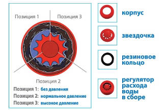
The principle of operation is based on a combination of the functions of a balancing valve, a water flow regulator, and a differential pressure calibrator, which changes position when the pressure setpoint increases or decreases.
- Two-line water flow regulators. They consist of a turbulent throttle and a constant pressure differential valve. With a decrease in the pressure in the outlet hydraulic line, the valve spool, moving, increases the working gap, which equalizes the value.
- Three-way water flow regulators. The pressure relief valve parallel to the regulated throttle operates in the overflow mode.This makes it possible to “dump” the excess into the cavity above the spool when the outlet pressure increases, which leads to its displacement and equalization of values.
Most water flow controllers are classified as direct-acting valves. RRs of indirect action are structurally more complicated and more expensive, which makes their use rare. The design includes a controller (programmable), a control valve and a sensor.
In the catalogs of some manufacturers, combined models are presented with the additional possibility of installing an electric actuator, which is functionally equivalent to a valve and a control mechanism. Allows you to achieve the optimal mode with limited water consumption.
When buying devices on the websites of suppliers, a calculator is often provided with the following fields to fill in - important credentials:
- Required water consumption (m3 / h).
- Excessive differential (potential losses at the regulator).
- Pressure in front of the device.
- Maximum temperature.
The calculation algorithm facilitates the selection and allows you to check the device for cavitation.