What is a schematic diagram
You can read the academic definition of a schematic diagram on Wikipedia, here I will remind you:
A schematic diagram is a drawing made using conventional symbols and showing the interaction of elements of a device or prefabricated unit, without their physical location.
The main purpose of the schematic diagram is to show how the installation elements are connected and in what sequence.
Designations on normative schematic diagrams are carried out by conventions, according to GOST documents. For heating, these are GOST 21.609-83, GOST 21-606-95: Standards for the implementation of drawings of thermal equipment inside a building.
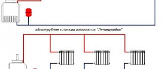
It is worth noting that for heating systems in the network you can find a lot of visual schematic diagrams, where instead of normative symbols, pictures showing the elements of the heating system are used.
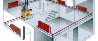
What is a furnace
In this article I will show you a basic diagram of a furnace, so it doesn't hurt to remember what it is.
The furnace of a private house is a room located inside a house or an annex, in which the equipment of the heating system of the house is planned and will be placed, namely, one or two heating boilers with a capacity of not more than 100 kW, each.
Premises for the furnace require special preparation. For them, the size, location, ventilation and other parameters that must be observed are normalized. Read more here.
Drawing of the heating system of a private household
In the process of executing the drawing of the heating system, all assembly units and individual elements should be drawn. A prerequisite should be the setting of exact dimensions with an acceptable degree of error.
The diameters of all pipelines that will be involved in the heating system must be indicated on the drawing. Ideally, the drawing of the heating system of a private house is carried out by one designer, and then his work is checked by another specialist and approved by the chief engineer or the head of the company.
If the inspector pays attention to the defects in the drawing, the latter is sent for revision, since errors in heating systems should not take place. Carefully executed schematic diagrams of hot water heating systems contain sections and plans that are clearly executed with all dimensions and designations, so that workers can control the assembly process according to the attached drawing.
All symbols of the heating system are affixed directly to the drawing and are deciphered in the specification or in the technical appendix. All distances are marked in the areas where pipelines are laid and heating radiators are installed, cross-sections at the joints and branches.
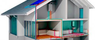
Schematic diagram as part of a house project
The construction of a private house, which we call correct, should be carried out according to the project. It doesn't matter what kind of project it will be, ready-made with modifications or individual, the main thing it should be.
An integral part of the house project is the engineering part. It includes drawings for all engineering equipment and engineering networks in and out of the house. The heating part of the project is called Heating and Ventilation Workshop Drawings. A set of OV drawings consists of the following sheets (for example):
- Heating system diagram;
- Heating schemes with radiators and / or warm floors;
- Connecting manifold cabinets;
- Schematic diagram of the furnace.
As you can see, the schematic diagram of the furnace is included in the set of working drawings for the OV.
Heating system technological map
A professionally drawn up flow chart for the heating system will be an excellent help for craftsmen who will be engaged in pipe connections and installation of heating equipment.
In order for the heating system to be safe, it is necessary to provide for the creation of an effective ventilation system capable of removing combustion products and maintaining optimal air exchange. If the system is being forced, then the notation will be as follows:
- The compensator is designated by the letter K,
- Main risers of the GST heating system,
- GW horizontal branch,
- All other risers of the heating system Art.
When the drawings of the heating system are carried out professionally in special programs, then a cut in the most important areas should be a prerequisite. In addition, the flow chart for the heating system must necessarily be carried out to scale, and in the most readable version.
If some of the joints are too small, a callout is made on a larger scale so that the installation workers can pay attention to all the features of the assembly.
Symbols of heating schemes
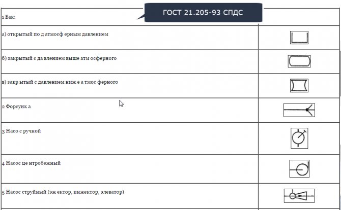
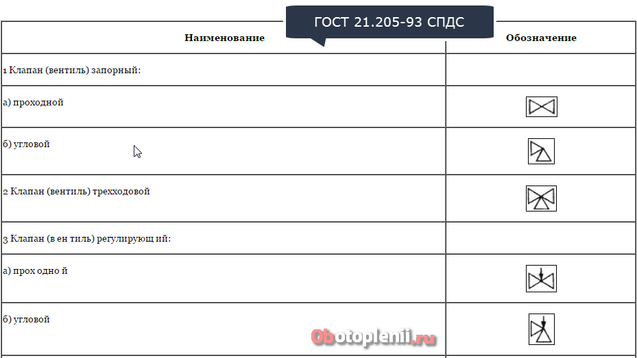
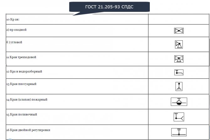
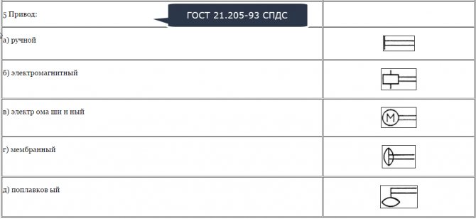
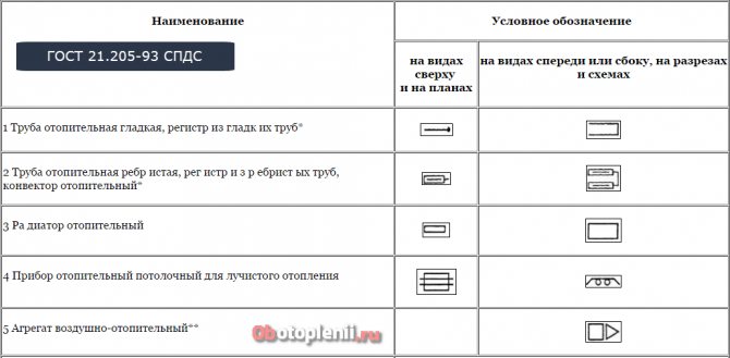
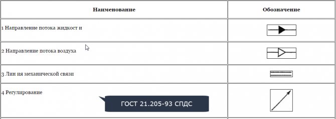
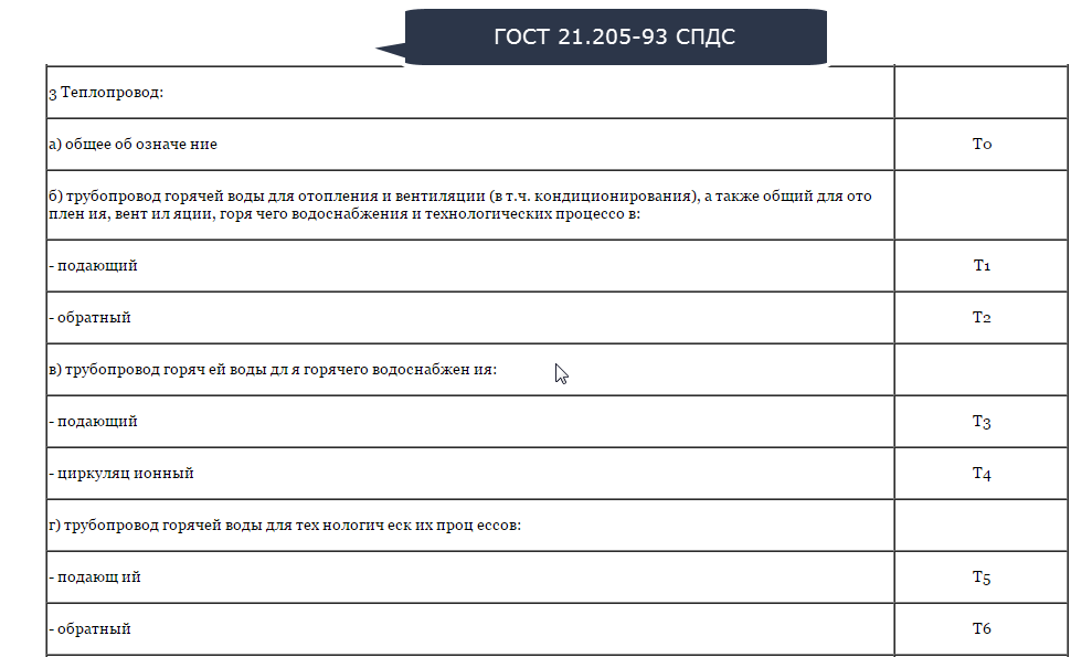
Unlike visual heating schemes, in which the designations are more or less clear, in the correct schematic diagram, the designations require explanation. You can find them in GOST 21.205-93 SPDS: Symbols of elements of sanitary systems. Below are 9 cards with symbols on the drawings of heating systems.
Symbols of tanks and pumps
Valve symbols
Crane Symbols
Drive Symbols
Pipe Symbols
Legend for driving directions
Piping Symbols
Designations on electrical diagrams. General information.
Hello dear friends. In this article, we will analyze the designations on electrical diagrams. Reading electrical diagrams is an extremely important skill of instrumentation and automation specialists, electromechanics, electrical fitters, designers of electrical devices, circuits and networks. Nevertheless, for a person without special training, often, even the simplest electrical circuit (especially its elements) is a completely incomprehensible product of someone's professional activity.
Designations on electrical circuits have a long history - even in the Soviet era, the development of instrumentation and electrical engineering was one of the military-strategic directions and great importance was attached to it. In this regard, a unified understanding of the meaning of the circuit elements was required. Therefore, it was necessary to create a unified graphic designation of electrical elements, rules for drawing up electrical circuits. This work was carried out by the USSR State Committee for Standardization within the framework of the Unified System for Design Documentation (ESKD) and GOST.
Within the framework of this article, it is impossible to consider all the subtleties of designations, rules, principles of constructing electrical circuits, since GOST is a rather voluminous document with an abundance of graphic designations and notes.
Electrical wiring in drawings
Electrical wiring is a general term that refers to low-resistance conductors that transfer electrical current from one element of the circuit to another, for example, from a source to a consumer or from a transformer to a switch with further distribution. This is the most primitive explanation, since there are a large number of types of electrical wiring. An image of polymer-insulated wires that go to the switch from somewhere from the wall is immediately born in the head of the layman.
Strange as it may seem, but copper tracks on a textolite board are also a variant of electrical wiring. As well as high voltage power lines. In the diagrams, the designation of electrical wires is most often performed in the form of a line leading from one element of the circuit to another.
Strictly speaking, GOST proposes to divide the designations of conductors into groups:
- electrical connections
- wires
- cables
The term "wiring plan" is not a completely correct terminological unit, since "wiring" in this case should be understood not only the wires themselves, but also the cables. If we take this term as a designation on the electrical diagrams of elements, then the list will expand to insulators, transformers, protection and grounding devices, and so on.
About sockets
It is well known to everyone that a socket is a plug-type device designed for a non-rigid (with the possibility of manual disconnection) connection of an electrical network (circuit) with a receiver or control device. The graphic representation of the outlet on the diagram is regulated by GOST, which sets the rules for the depiction of devices and devices for internal lighting and power consumption.
Sockets are divided into groups:
- for open installation
- for hidden installation
- blocks with switch and socket
In each group, there are subspecies depending on the polarity and the presence of a protective contact:
- single-pole
- bipolar
- bipolar with protective contact
- three-pole
- three-pole with protective contact
About switches
Switches are devices for breaking a section of an electrical circuit in a manual or automatic mode. Just like sockets on the electrical circuit, switches (together with switches) are designated depending on their operating parameters and design, as well as the degree of protection.
Switch designs:
- single-pole
- single pole double
- single pole triple
- bipolar
- three-pole
The designation of the switch on the electrical diagram is also regulated by GOST, which establishes the rules for the depiction of devices and devices for internal lighting and power consumption.
Protection devices
The protection devices include a number of reusable and disposable devices that are completely different in design, areas of application, response speed, reliability, operating conditions, as well as taking into account many other parameters.
For example, everyone knows well fuses in electronic household appliances, fusible disposable plugs in old apartment switchboards. Circuit breakers of various types and designs are also well known. Less known to a wide range of people are high-voltage air circuit breakers, arresters and other protection devices.
The main function of all protection devices is to forcibly break a section of the electrical circuit with a sudden increase in the current load or with a sudden positive voltage surge. Designations of other types of overload circuit protection devices are regulated by other regulatory and technical documents.
About grounding
Grounding is such a connection of the conductive parts of an electrical device or electrical machine (of another design) to the ground, which has a negative potential, at which a possible breakdown to the case will not cause destruction or risk electric shock, diverting this charge to the ground.
GOST distinguishes the following types of graphic representation of this type of protection:
- grounding (general designation)
- silent grounding (clean)
- protective earth
- electrical connection to the housing (ground)
As a result, in addition to the fact that the designation of grounding on electrical circuits corresponds to the basic way of drawing this element, the drawing of the grounding is of great importance, depending on the device or the section of the circuit where the grounding is used. An important point in the designation of elements of electrical circuits is the size of these elements, as well as the rules and sequence for drawing various sections of the electrical circuit.
For example, their own characteristics are indicated on the electrical circuits of the elements of electronic devices, devices operating on logical signals, etc.
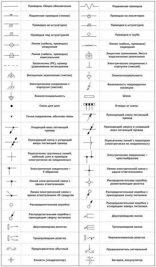
Let's continue the topic of conditional graphic images of electrical elements on diagrams, drawings and plans. Above, we have discussed the general points. Now we will give visual images of such elements as sockets, switches, electrical panels and much more.
Designations of electrical wiring and connections
Contact designations and contact connections
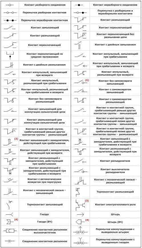
Note:
- The self-return designation (or its absence) is used only when it is necessary to specifically emphasize the presence of such a function in the contact assembly.
- Deceleration occurs when moving in the direction from the edge of the arc to its center. The designation of the retarder is allowed to be depicted from the opposite side of the designation of the moving contact.
- This contact designation is used in the spaced-apart mode of displaying the relay.
- The connection is pin detachable, coaxial (high-frequency).
Designation of various switches
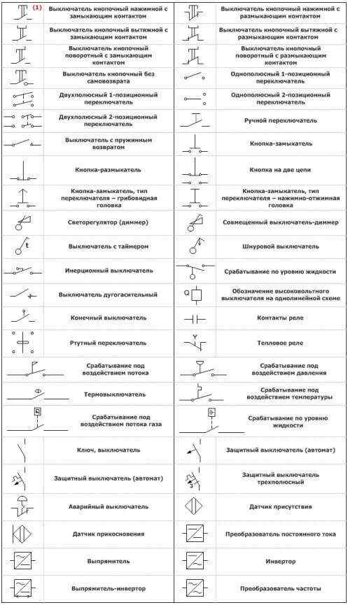
Note:
- Pushbutton switches are self-resetting, except those designated as non-self-resetting.
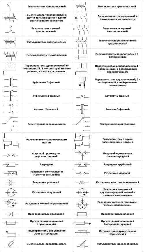
Designations of switches, switches and arresters
Designation of light sources and lighting devices
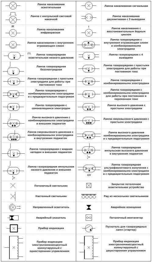
Note:
To indicate the type of lamps, letter designations are used:
- EL - electroluminescent
- FL - fluorescent.
Alphanumeric designations of terminals and wires
Clamps.
AC electrical device connection terminal:
- U - 1st phase
- V - 2nd phase
- W - 3rd phase
- N - neutral wire
- PE - protective conductor
- E - ground wire
- TE - silent ground wire
- MM - ground wire (body)
- CC - equipotential wire.
Wires.
Alternating current - wire designation:
- L - general designation of the phase conductor
- L1 - 1st phase
- L2 - 2nd phase
- L3 - 3rd phase
- N - neutral wire (working zero).
Direct current - wire designation:
- L + - positive pole
- L- - negative pole
- M - middle wire.
Others:
- PE - protective wire with grounding
- PU - ungrounded protective wire
- PEN - combined protective and neutral wire
- E - grounding wire
- TE - silent ground wire
- MM - ground wire (body)
- CC - equipotential wire.
Color coding for electrical wiring
Phase conductor designation (L) - insulation color:
White, red, brown, black, orange, gray, purple, turquoise, pink.
Designation of neutral and protective conductors:
- Blue color - neutral conductor (N), middle wire (direct current)
- Yellow-green color - grounding, protective and neutral protective conductors (PE)
- Yellow-green color with blue marks at the ends - combined zero and protective conductors (PEN).
Blue marks are applied during installation at the ends of the line.
Functional assignment of conductors according to color coding.
- Black color - conductors of power circuits
- Red color - conductors of control, signaling and measurement circuits
- Blue color - conductors of control, signaling and measurement circuits for direct current
- Blue color - zero working conductors
- The combination of yellow and green colors - protection and grounding conductors.
We will be glad if you subscribe to our Blog!
[wysija_form id = "1"]
Furnace schematic diagram - example
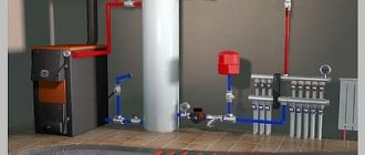
I propose to see an example, a furnace diagram from a finished project of a private house, with an area of about 350 meters.
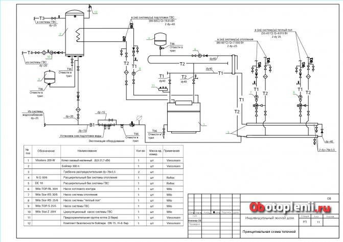
In this example of a basic diagram of a furnace, a wall-mounted gas boiler is used, as the most popular type of heating boiler. Similar wall-mounted gas boilers are used in houses up to 300 sq. meters, the power of the boilers is small, from 30-50 kW. The construction of the wall-mounted gas boiler is very compact and includes all the necessary elements. Due to this, wall-mounted gas boilers are often called mini boiler rooms.
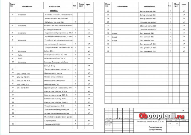
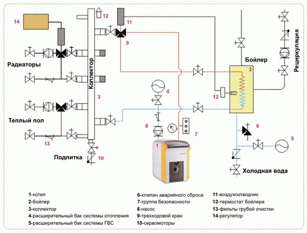
Description of the circuit
This scheme uses a two-circuit wall-mounted gas boiler from Viesmann (1), with a capacity of 8.0-31.7 kW. In addition to the heating system, the scheme provides for a hot water supply system (2) (a boiler of the same company for 300 liters) and a heating system with warm floors.
In heating and hot water systems, expansion tanks (4), (5) from Reflex are used. To improve circulation in the systems, Wilo pumps are provided:
- Boiler circuit pump (6);
- Heating system pump (7);
- Underfloor heating system pump (8);
- DHW pump (9) and circulation pump (10).
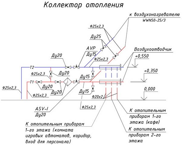
Particular attention should be paid to two distribution manifolds dу = 76 × 3.5 (according to scheme 3).
For safety, there are two Vissmann groups:
Boiler safety group 3 bar (11);
Boiler safety kit (12) DN15, H = 6 bar.
All elements of the circuit diagram are detailed in the specification for the circuit.