Recommended rates of air exchange rate
During the design of the building, the calculation of each individual section is performed. In production, these are workshops, in residential buildings - apartments, in a private house - floor blocks or separate rooms.
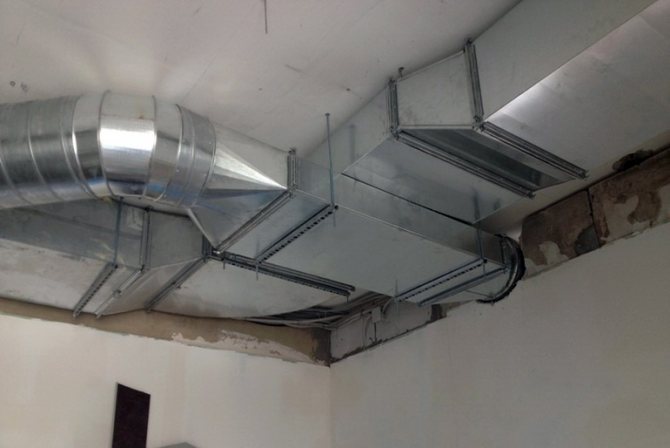
Before installing the ventilation system, it is known what the routes and sizes of the main lines are, what geometry ventilation ducts are needed, what pipe size is optimal.
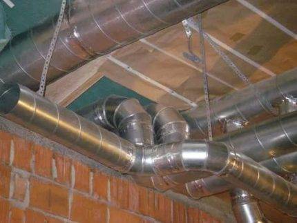
Do not be surprised by the overall dimensions of the air ducts in catering establishments or other institutions - they are designed to remove a large amount of used air
Calculations related to the movement of air flows inside residential and industrial buildings are classified as the most difficult, therefore, experienced qualified specialists are required to deal with them.
The recommended air speed in the ducts is indicated in SNiP - regulatory state documentation, and when designing or commissioning objects, they are guided by it.
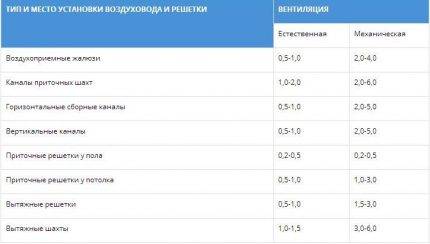
The table shows the parameters that should be adhered to when installing a ventilation system. The numbers indicate the speed of movement of air masses in the places of installation of channels and gratings in generally accepted units - m / s
It is believed that indoor air speed should not exceed 0.3 m / s.
Exceptions are temporary technical circumstances (for example, repair work, installation of construction equipment, etc.), during which the parameters can exceed the standards by a maximum of 30%.
In large rooms (garages, production halls, warehouses, hangars), instead of one ventilation system, two often operate.
The load is divided in half, therefore, the air speed is selected so that it provides 50% of the total estimated volume of air movement (removal of contaminated or supply of clean air).
In the event of force majeure circumstances, it becomes necessary to abruptly change the air speed or to completely stop the operation of the ventilation system.
For example, according to fire safety requirements, the speed of air movement is reduced to a minimum in order to prevent the spread of fire and smoke in adjacent rooms during a fire.
For this purpose, cut-off devices and valves are mounted in the air ducts and in the transition sections.
Features of the movement of gases
As mentioned above, three parameters are involved in the calculations carried out in the construction of ventilation: the flow rate and speed of air masses, as well as the cross-sectional area of the air ducts. Of these parameters, only one is normalized - this is the cross-sectional area. In addition to residential premises and childcare facilities, SNiP does not regulate the permissible air speed in the air duct.
In the reference literature, there are recommendations for the movement of gases flowing through ventilation networks. Values are recommended based on the application, specific conditions, possible pressure losses and noise performance. The table reflects the recommended data for forced ventilation systems.
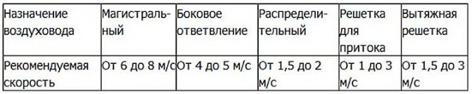
For natural ventilation, the movement of gases is taken with values of 0.2 - 1 m / s.
The subtleties of choosing an air duct
Knowing the results of aerodynamic calculations, it is possible to correctly select the parameters of the air ducts, or rather, the diameter of the round and the dimensions of the rectangular sections.
In addition, in parallel, you can select a device for forced air supply (fan) and determine the pressure loss during the movement of air through the channel.
Knowing the value of the air flow and the value of the speed of its movement, it is possible to determine what section of the air ducts will be required.
For this, a formula is taken that is the opposite of the formula for calculating the air flow: S = L / 3600 * V.
Using the result, you can calculate the diameter:
D = 1000 * √ (4 * S / π)
Where:
- D is the diameter of the duct section;
- S - cross-sectional area of air ducts (air ducts), (m2);
- π - number "pi", a mathematical constant equal to 3.14 ;.
The resulting number is compared with the factory standards approved by GOST, and the products that are closest in diameter are selected.
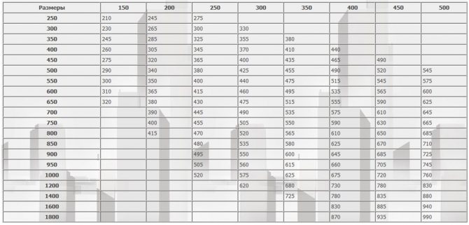
If it is necessary to choose rectangular rather than round air ducts, then instead of the diameter, determine the length / width of the products.
When choosing, they are guided by an approximate cross-section, using the a * b ≈ S principle and size tables provided by the manufacturers. We remind you that according to the norms, the ratio of width (b) and length (a) should not exceed 1 to 3.
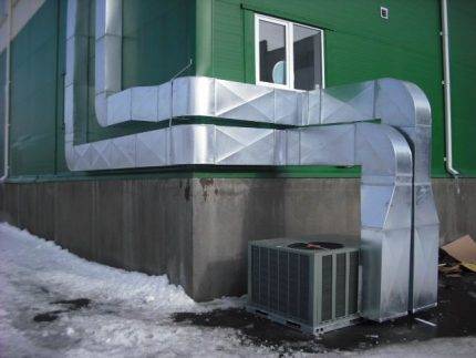
Air ducts with rectangular or square cross-sections are ergonomically shaped, which allows them to be installed close to the walls. This is used when equipping home hoods and masking pipes over ceiling hinges or over kitchen cabinets (mezzanines)
Generally accepted standards for rectangular ducts: minimum dimensions - 100 mm x 150 mm, maximum - 2000 mm x 2000 mm. Round air ducts are good because they have less resistance, respectively, they have minimal noise levels.
Recently, convenient, safe and lightweight plastic boxes have been produced specifically for intra-apartment use.
Calculation of air flow
It is important to correctly calculate the area of sections of any shape, both round and rectangular. If the size is not suitable, it will not be possible to ensure the correct air balance. A too large air line will take up a lot of space. This will reduce the area in the room and cause discomfort to the residents. With the wrong calculation and selection of a very small channel size, strong drafts will be observed. This is due to the strong increase in air flow pressure.
Cross-section design
When a round duct turns into a square, the speed will change
To calculate the speed at which air will pass through the pipe, you need to determine the cross-sectional area. For the calculation, the following formula is used S = L / 3600 * V, where:
- S is the cross-sectional area;
- L is the air consumption in cubic meters per hour;
- V is the speed in meters per second.
For round ducts, it is necessary to determine the diameter using the formula: D = 1000 * √ (4 * S / π).
If the duct is rectangular, and not round, instead of the diameter, you need to determine its length and width. When installing such a duct, an approximate cross-section is taken into account. It is calculated by the formula: a * b = S, (a - length, b - width).
There are approved standards according to which the ratio of width and length should not exceed 1: 3. It is also recommended to use tables with typical dimensions offered by air duct manufacturers.
Round ducts have an advantage. They are characterized by a lower level of resistance, therefore, during operation of the ventilation system, the level of noise and vibration will be minimized as much as possible.
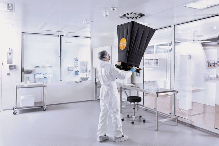
What device is used to measure the speed of air movement
All devices of this type are compact and easy to use, although there are some subtleties here.
Air velocity measuring instruments:
- Vane anemometers
- Temperature anemometers
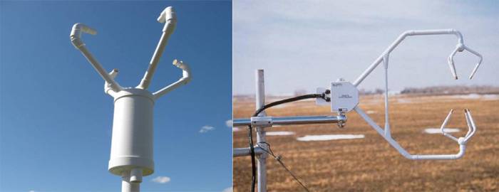
- Ultrasonic anemometers
- Pitot tube anemometers
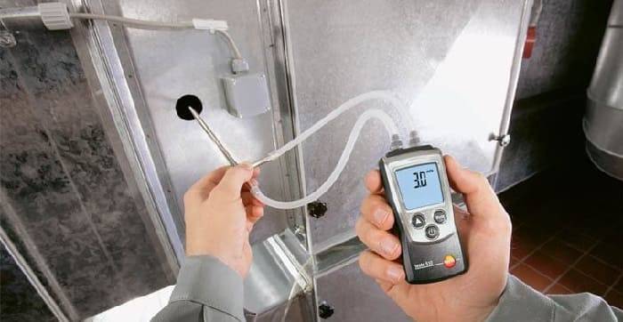
- Differential pressure gauges
- Balometers
Vane anemometers are one of the simplest devices in design. The flow rate is determined by the rotation speed of the impeller of the device.
Temperature anemometers have a temperature sensor. In a heated state, it is placed in the air duct and, as it cools, the air flow rate is determined.
Ultrasonic anemometers mainly measure wind speed. They work on the principle of detecting the difference in sound frequency at selected test points of the air flow.
Pitot tube anemometers are equipped with a special small diameter tube. It is placed in the middle of the duct, thereby measuring the difference in total and static pressure. These are one of the most popular devices for measuring air in the duct, but at the same time they have a drawback - they cannot be used with a high concentration of dust.
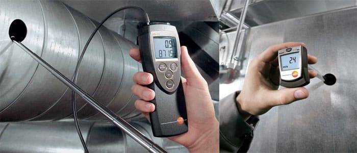
Differential pressure gauges can measure not only speed, but also air flow. Complete with a pitot tube, this device can measure air flows up to 100 m / s.
Balometers are most effective for measuring air velocity at the outlet of ventilation grilles and diffusers. They have a funnel that captures all the air coming out of the ventilation grille, thereby minimizing the measurement error.
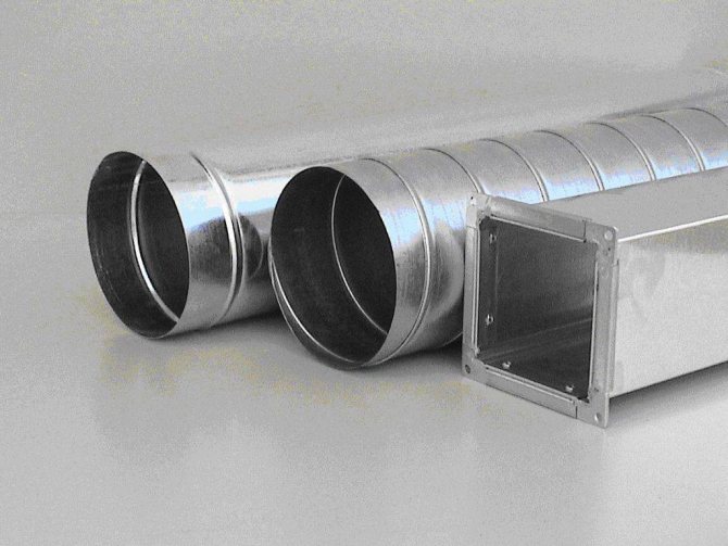
Sectional shapes
According to the cross-sectional shape, pipes for this system are divided into round and rectangular. Round are mainly used in large industrial plants. Since they require a large area of the room. Rectangular sections are well suited for residential buildings, kindergartens, schools and clinics. In terms of noise level, pipes with a circular cross-section are in the first place, since they emit a minimum of noise vibrations. There are slightly more noise vibrations from pipes with a rectangular cross-section.
Pipes of both sections are made most often of steel. For pipes with a circular cross-section, steel is used less hard and elastic, for pipes with a rectangular cross-section - on the contrary, the harder the steel, the stronger the pipe.
In conclusion, I would like to say once again about the attention to the installation of air ducts, to the calculations carried out. Remember, how correctly you do everything, the functioning of the system as a whole will be so desirable. And, of course, we must not forget about safety. The parts for the system should be chosen carefully. The main rule should be remembered: cheap does not mean high quality.
Material and cross-sectional shape of air ducts
Round air ducts are most often used in large factories. This is due to the fact that their installation requires many square meters of floor space. For residential buildings, rectangular sections are most suitable; they are also used in clinics, kindergartens.
Steel is the most commonly used pipe for making pipes. For a round section, it should be elastic and firm, for rectangular sections, it should be softer. Pipes can be made of textile and polymeric materials.
Calculation rules
Noise and vibration are closely related to the speed of air masses in the ventilation duct. After all, the flow that passes through the pipes is capable of creating variable pressure that can exceed normal parameters if the number of turns and bends is greater than optimal values. When the resistance in the ducts is high, the air speed is significantly lower, and the efficiency of the fans is higher.
Many factors affect the vibration threshold, for example - pipe material
Standard noise emission standards
In SNiP, certain standards are indicated that affect premises of a residential, public or industrial type. All standards are indicated in tables. If the accepted standards are increased, it means that the ventilation system is not designed properly. In addition, exceeding the sound pressure standard is permissible, but only for a short time.
If the maximum permissible values are exceeded, it means that the channel system was created with any shortcomings, which should be corrected in the near future.The fan power can also influence the vibration level exceeding. The maximum air velocity in the duct should not contribute to an increase in noise.
Evaluation principles
Various materials are used for the manufacture of ventilation pipes, the most common of which are plastic and metal pipes. The shapes of the air ducts have different sections, ranging from round and rectangular to ellipsoidal. SNiP can only indicate the dimensions of the chimneys, but not standardize the volume of air masses in any way, since the type and purpose of the premises can differ significantly. The prescribed norms are intended for social facilities - schools, preschool institutions, hospitals, etc.
All dimensions are calculated using certain formulas. There are no specific rules for calculating the air speed in ducts, but there are recommended standards for the required calculation, which can be seen in SNiPs. All data is used in the form of tables.
It is possible to supplement the given data in this way: if the hood is natural, then the air velocity should not exceed 2 m / s and be less than 0.2 m / s, otherwise the air flows in the room will be updated badly. If ventilation is forced, then the maximum allowable value is 8-11 m / s for main air ducts. If this standard is higher, the ventilation pressure will be very high, resulting in unacceptable vibration and noise.
General principles of calculation
Air ducts can be made of different materials (plastic, metal) and have different shapes (round, rectangular). SNiP regulates only the dimensions of the exhaust devices, but does not standardize the amount of supplied air, since its consumption, depending on the type and purpose of the room, can vary greatly. This parameter is calculated using special formulas that are selected separately. The norms are established only for social facilities: hospitals, schools, preschool institutions. They are spelled out in SNiPs for such buildings. At the same time, there are no clear rules for the speed of air movement in the duct. There are only recommended values and norms for forced and natural ventilation, depending on its type and purpose, they can be viewed in the corresponding SNiPs. This is reflected in the table below. Air speed is measured in m / s.
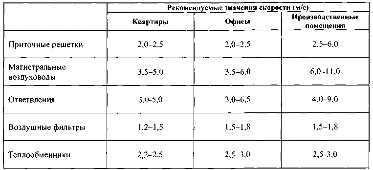
Recommended air speeds
The data in the table can be supplemented as follows: with natural ventilation, the air speed cannot exceed 2 m / s, regardless of its purpose, the minimum allowable is 0.2 m / s. Otherwise, the renewal of the gas mixture in the room will be insufficient. With forced exhaust, the maximum allowable value is considered to be 8 -11 m / s for main air ducts. You should not exceed these standards, since this will create too much pressure and resistance in the system.
Basic formulas for aerodynamic calculation
The first step is to make an aerodynamic calculation of the line. Recall that the longest and most loaded section of the system is considered the main duct. Based on the results of these calculations, the fan is selected.
Just do not forget about linking the rest of the branches of the system
It is important! If it is not possible to bind the duct branches within 10%, diaphragms should be used. The resistance coefficient of the diaphragm is calculated using the formula:
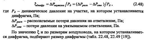
If the discrepancy is more than 10%, when the horizontal duct enters the vertical brick channel, rectangular diaphragms must be placed at the junction.
The main task of the calculation is to find the pressure loss. At the same time, choosing the optimal size of the air ducts and controlling the air speed.The total pressure loss is the sum of two components - the pressure loss along the length of the ducts (by friction) and the loss in local resistances. They are calculated by the formulas
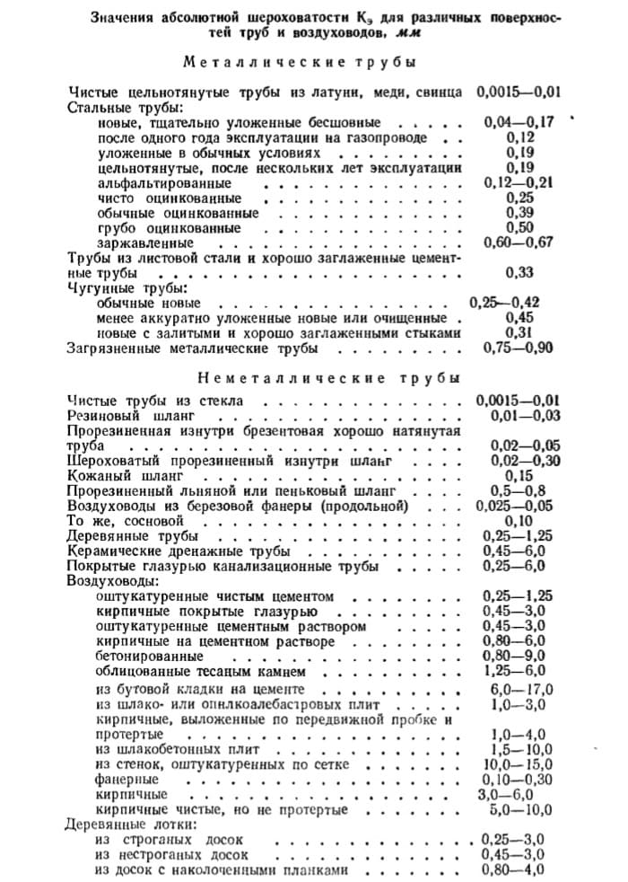
These formulas are correct for steel ducts, for all others a correction factor is entered. It is taken from the table depending on the speed and roughness of the air ducts.
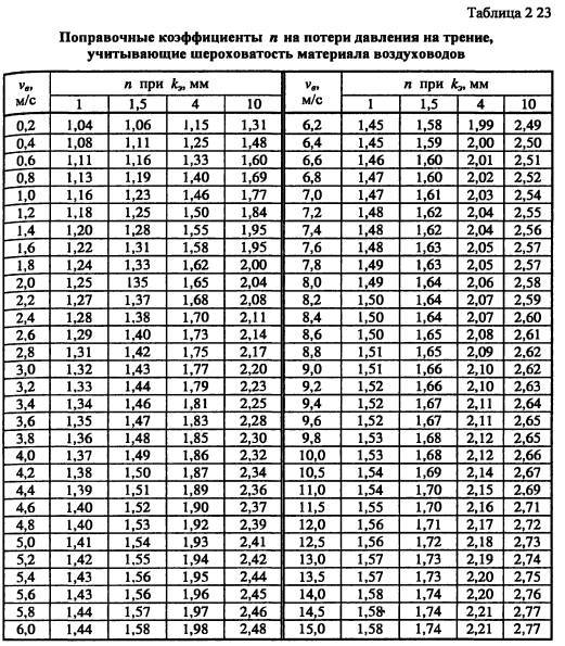
For rectangular air ducts, the equivalent diameter is taken as the calculated value.
Let us consider the sequence of aerodynamic calculation of air ducts using the example of the offices given in the previous article, using the formulas. And then we'll show how it looks in Excel.
Calculation example
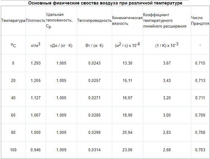
According to calculations in the office, the air exchange is 800 m3 / hour. The task was to design air ducts in offices no more than 200 mm high. The dimensions of the premises are given by the customer. Air is supplied at a temperature of 20 ° C, air density 1.2 kg / m3.
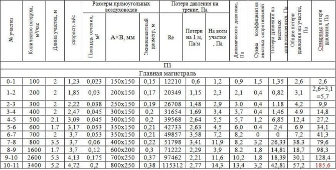
It will be easier if the results are entered into a table of this type
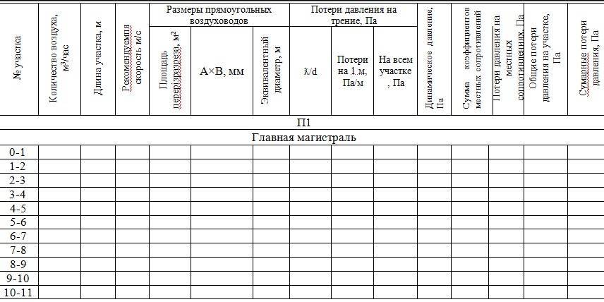
First, we will do the aerodynamic calculation of the main line of the system. Now everything is in order:
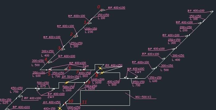
We divide the highway into sections along the supply grilles. We have eight gratings in our room, each with 100 m3 / hour. It turned out 11 sites. We enter the air consumption at each section in the table.
- We write down the length of each section.
- The recommended maximum speed inside the duct for office premises is up to 5 m / s. Therefore, we select such a size of the duct so that the speed increases as we approach the ventilation equipment and does not exceed the maximum. This is to avoid ventilation noise. We take for the first section we take an air duct 150x150, and for the last 800x250.
V1 = L / 3600F = 100 / (3600 * 0.023) = 1.23 m / s.V11 = 3400/3600 * 0.2 = 4.72 m / s
We are satisfied with the result. We determine the size of the air ducts and the speed using this formula at each site and enter it into the table.
- We start calculating the pressure loss. We determine the equivalent diameter for each section, for example, the first de = 2 * 150 * 150 / (150 + 150) = 150. Then we fill in all the data necessary for the calculation from the reference literature or calculate: Re = 1.23 * 0.150 / (15.11 * 10 ^ -6) = 12210. λ = 0.11 (68/12210 + 0.1 / 0.15) ^ 0.25 = 0.0996 The roughness of different materials is different.
- Dynamic pressure Pd = 1.2 * 1.23 * 1.23 / 2 = 0.9 Pa is also recorded in the column.
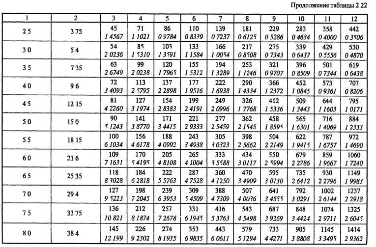
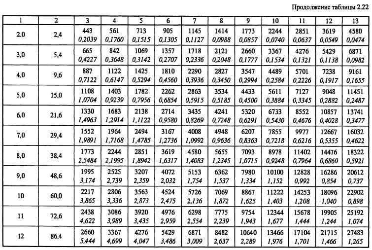
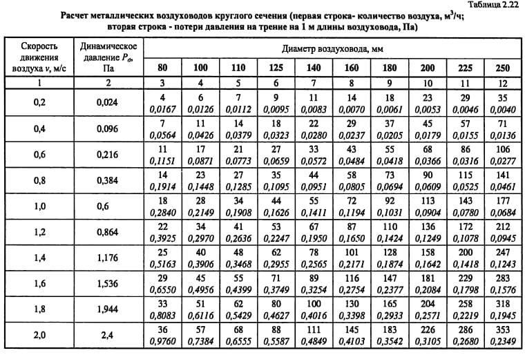
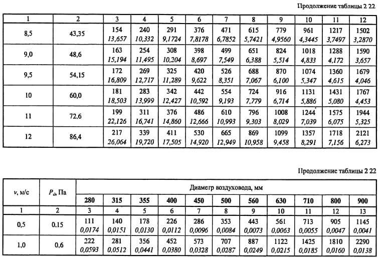
- From table 2.22, we determine the specific pressure loss or calculate R = Pd * λ / d = 0.9 * 0.0996 / 0.15 = 0.6 Pa / m and enter it into a column. Then, at each section, we determine the pressure loss due to friction: ΔРtr = R * l * n = 0.6 * 2 * 1 = 1.2 Pa.
- We take the coefficients of local resistances from the reference literature. In the first section, we have a lattice and an increase in the duct in the sum of their CMC is 1.5.
- Pressure loss in local resistances ΔPm = 1.5 * 0.9 = 1.35 Pa
- We find the sum of the pressure losses in each section = 1.35 + 1.2 = 2.6 Pa. And as a result, the pressure loss in the entire line = 185.6 Pa. the table by that time will have the form
Further, the remaining branches are calculated using the same method and their linking. But let's talk about this separately.
Ventilation system calculation
Ventilation is understood as the organization of air exchange to ensure the specified conditions, in accordance with the requirements of sanitary standards or technological requirements in any particular room.
There are a number of basic indicators that determine the quality of the air around us. It:
- the presence of oxygen and carbon dioxide in it,
- the presence of dust and other substances,
- unpleasant odor
- humidity and air temperature.
Only a correctly calculated ventilation system can bring all these indicators to a satisfactory state. Moreover, any ventilation scheme provides for both the removal of waste and the supply of fresh air, thus ensuring air exchange in the room. To start calculating such a ventilation system, it is necessary, first of all, to determine:
1.
The volume of air that needs to be removed from the room, guided by the data on the rates of air exchange for different rooms.
Standardized air exchange rate.
| Household premises | Air exchange rate |
| Living room (in an apartment or dorm) | 3 m3 / h per 1 m2 of residential premises |
| Apartment or dorm kitchen | 6-8 |
| Bathroom | 7-9 |
| Shower room | 7-9 |
| Restroom | 8-10 |
| Laundry (household) | 7 |
| Walk-in closet | 1,5 |
| Pantry | 1 |
| Industrial premises and large premises | Air exchange rate |
| Theater, cinema, conference hall | 20-40 m3 per person |
| Office space | 5-7 |
| Bank | 2-4 |
| A restaurant | 8-10 |
| Bar, cafe, beer hall, billiard room | 9-11 |
| Kitchen room in a cafe, restaurant | 10-15 |
| Supermarket | 1,5-3 |
| Pharmacy (trading floor) | 3 |
| Garage and auto repair shop | 6-8 |
| Toilet (public) | 10-12 (or 100 m3 for 1 toilet) |
| Dance hall, disco | 8-10 |
| Smoking room | 10 |
| Server | 5-10 |
| Gym | Not less than 80 m3 for 1 student and not less than 20 m3 for 1 spectator |
| Hairdresser (up to 5 workplaces) | 2 |
| Hairdresser (more than 5 jobs) | 3 |
| Stock | 1-2 |
| Laundry | 10-13 |
| Swimming pool | 10-20 |
| Industrial paint shop | 25-40 |
| Mechanical workshop | 3-5 |
| Classroom | 3-8 |
Knowing these standards, it is easy to calculate the amount of air removed.
L = Vpom × Kr (m3 / h) L - amount of exhaust air, m3 / h Vpom - room volume, m3 Cr - air exchange rate
Without going into details, because here I am talking about simplified ventilation, which, by the way, is not even in many reputable establishments, I will say that in addition to the multiplicity, you also need to take into account:
- how many people are in the room,
- how much moisture and heat is released,
- the amount of CO2 emitted according to the permissible concentration.
But to calculate a simple ventilation system, it is enough to know the minimum required air exchange for a given room.
2.
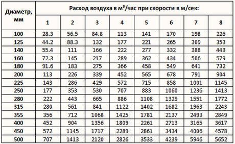
Having determined the required air exchange, it is necessary to calculate the ventilation ducts. Mostly vent. the channels are calculated according to the permissible speed of air movement in it:
V = L / 3600 × F V - air velocity, m / s L - air consumption, m3 / h F - sectional area of ventilation ducts, m2
Any vent. the channels are resistant to air movement. The higher the air flow rate, the greater the resistance. This, in turn, leads to a pressure loss, which is generated by the fan. Thereby, decreasing its performance. Therefore, there is an admissible speed of air movement in the ventilation duct, which takes into account economic feasibility or the so-called. a reasonable balance between duct size and fan power.
Permissible speed of air movement in ventilation ducts.
| A type | Air speed, m / s |
| Main air ducts | 6,0 — 8,0 |
| Side branches | 4,0 — 5,0 |
| Distribution ducts | 1,5 — 2,0 |
| Supply grilles at the ceiling | 1,0 – 3,0 |
| Exhaust grilles | 1,5 – 3,0 |
In addition to losses, noise also increases with speed. While adhering to the recommended values, the noise level during air movement will be within the normal range. When designing air ducts, their cross-sectional area should be such that the speed of air movement along the entire length of the air duct is approximately the same. Since the amount of air along the entire length of the duct is not the same, its cross-sectional area should increase with an increase in the amount of air, i.e., the closer to the fan, the larger the cross-sectional area of the air duct, if we speak from exhaust ventilation.
In this way, a relatively uniform air velocity can be ensured along the entire length of the duct.
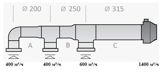
Section A. S = 0.032m2, air speed V = 400/3600 x 0.032 = 3.5 m / s Section B. S = 0.049m2, air speed V = 800/3600 x 0.049 = 4.5 m / s Section C . S = 0.078m2, air speed V = 1400/3600 x 0.078 = 5.0 m / s
3.
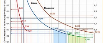
Now it remains to choose a fan. Any duct system creates a pressure loss, which creates a fan, and as a result, reduces its performance. To determine the pressure loss in the duct, use the appropriate graph.
For section A with its length of 10m, the pressure loss will be 2Pa x 10m = 20Pa
For section B with its length of 10m, the pressure loss will be 2.3Pa x 10m = 23Pa
For section C with a length of 20m, the pressure loss will be 2Pa x 20m = 40Pa
The resistance of ceiling diffusers can be about 30 Pa if you choose the PF (VENTS) series. But in our case, it is better to use gratings with a larger open area, for example, the DP series (VENTS).
Thus, the total pressure loss in the duct will be about 113Pa. If a check valve and silencer are required, the losses will be even higher. When choosing a fan, this must be taken into account. The VENTS VKMts 315 fan is suitable for our system. Its capacity is 1540 m³ / h, and with a network resistance of 113 Pa, its capacity will decrease to 1400 m³ / h, according to its technical characteristics.
This is, in principle, the simplest method for calculating a simple ventilation system. In other cases, contact a specialist. We are always ready to make a calculation for any ventilation and air conditioning system, and offer a wide range of quality equipment.
Do I need to focus on SNiP
In all the calculations that we carried out, the recommendations of SNiP and MGSN were used. This normative documentation allows you to determine the minimum permissible ventilation performance, which ensures a comfortable stay of people in the room. In other words, SNiP requirements are aimed primarily at minimizing the cost of the ventilation system and the cost of its operation, which is important when designing ventilation systems for administrative and public buildings.
In apartments and cottages, the situation is different, because you are designing ventilation for yourself, and not for the average resident, and no one forces you to adhere to the recommendations of SNiP. For this reason, system performance can be either higher than the design value (for more comfort) or lower (to reduce energy consumption and system cost). In addition, the subjective feeling of comfort is different for everyone: for some, 30–40 m³ / h per person is enough, while for others, 60 m³ / h is not enough.
However, if you do not know what kind of air exchange you need to feel comfortable, it is better to adhere to the SNiP recommendations. Since modern air handling units allow you to adjust the performance from the control panel, you can find a compromise between comfort and economy already during the operation of the ventilation system.
How to estimate compressed air consumption?
How to determine the compressed air consumption? How to find out the compressed air consumption?
Very often, when expanding production and planning the purchase of compressor equipment, the question arises, how much compressor power is needed? How much air does it take to connect the equipment?
I propose to consider one of the calculation options, which allows you to calculate the compressed air consumption with maximum accuracy.
Immediately, I note that this Option is not always suitable, but only if you already have some kind of compressor with a receiver and you plan to increase the size of production and, accordingly, the consumption of compressed air.
- Find out the volume of the existing receiver.
- Fill the reservoir with compressed air up to the maximum operating pressure.
- Switch off the compressor and start consuming air.
- Using a stopwatch, measure the time during which the pressure in the receiver drops to the minimum permissible operating pressure. It is important that for sufficient calculation accuracy, the difference between the maximum and minimum pressure must be at least two atmospheres.
- Then calculate using the following formula:
The calculation is quite simple, for this you need:
Where: Q - consumption of compressed air by the system, l / min; Pн - pressure of the beginning of measurement, bar; Pк - pressure of the end of measurement, bar; Vр - receiver volume, l; t - Time during which the pressure drops from Pн to Pк
As a result, we got the exact consumption of compressed air by our system. Of course, measurements for such a calculation must be carried out during the maximum production load. This will avoid mistakes and underestimation of consumption.
If, for some reason, you cannot turn off the compressor, you can also use this formula. To do this, subtract the compressor capacity from the result.Do not forget about the dimensions of the numbers, subtract l / min from l / min.
When you plan to expand production, we add the consumption of new equipment to the result obtained (how to calculate it, read the article) and we get the total consumption of future production.
After obtaining the result, you can calculate the required performance of the future compressor. To do this, it is enough to add a stock to the calculated consumption. Usually 10-15%.
Why stockpile?
The margin is necessary to compensate for the inaccuracies allowed when measuring the capacity and in order for the compressor control system to provide the optimal number of compressor starts and stops.
We will talk about compressor control systems in the following articles.
Following this method, we will obtain an air flow value that will allow you to optimally select a compressor in full accordance with production requirements.
It should also be noted that by measuring consumption, in this way, we get the system's consumption together with losses, and we can estimate some of them.
Why part? The fact is that losses can be divided into two groups: constants arising from leaks in pipeline connections and variables arising as equipment deteriorates.
With the measurements described above, the permanent loss can be easily calculated. To do this, we pump up pressure into the receiver and stop the operation of all equipment. As in the previous case, we note the time of the pressure drop in the receiver and, using the formula, we get the result.
To get a complete picture, do not shut off valves at the entrance to the equipment, this will allow you to estimate losses not only in the pipelines, but also in the air hoses and connections on the equipment itself.
Why do we need to estimate losses?
Let me remind you that a compressor is an extremely inefficient system and its efficiency does not exceed 10%. This means that only 10% of the energy we can use in the form of compressed air energy. Everything else is spent on heating as a result of the work of compressing the air. Even if there are no leaks in the pneumatic line and all connectors and quick-release couplings are in good working order and are replaced as needed, leaks will still occur and they are not associated with pipelines, but with a pneumatic tool. During the operation of the tool, its natural wear occurs, an increase in gaps and aging of gaskets, etc., which entails an increase in air consumption during operation.
Making simple calculations, we find that the energy of compressed air is about 10 times more expensive than electricity. Those. compressed air energy is very expensive and, consequently, the losses in the compressed air system are very expensive.
Having received numerical data on losses, you yourself can estimate whether it is worth fighting with them or the losses are not significant and their cost is not great.
Practical example:
At one of the enterprises for the production of concrete products, we replaced the compressors for the shop for welding mesh cards. There were 6 devices for contact welding of mesh with pneumatic clamping of electrodes in the shop. Using the calculation given in this section, we estimated the shop floor consumption during operation (to improve accuracy, several measurements were taken per shift). The flow rate was found to be 11,500 l / min.
Then we took measurements at the end of the shift in order to estimate the losses on the shop floor. The losses turned out to be about 1200 l / min, at the level of 11%. Too much. Having examined the compressed air line, it turned out that these losses can be easily eliminated. Most of the connections in the system were poisoned. Rewinding, tightening and replacing some of the joints gave excellent results. After the work carried out, the losses amounted to 30 l / min. One day of work to fix the leaks and an excellent result. Reduce compressor room electricity costs by more than 10%.
Further, having eliminated constant losses, we compared the received consumption of the entire shop with the passport consumption of the equipment standing in it. In this case, it was not difficult. There were not many consumers in the shop. This comparison yielded impressive numbers. The loss of compressed air in the pneumatic cylinders was 2300 l / min, 23% of the total compressed air consumption.
To eliminate these losses, equipment repairs were required. It was produced in-house by the enterprise.
This example clearly shows how much energy the company wasted in wasted. Losses in only one shop amounted to 3500 l / min. This is approximately 22 kW. Those. the enterprise was constantly losing 22 kWh of electricity in only one workshop.
In conclusion, it should be noted that this method is quite accurate, and allows you to do without a flow meter, and at the same time, its use is not always possible. It is difficult to apply it in large enterprises with a branched pneumatic system and uneven consumption of compressed air, although it is quite applicable for individual workshops. The main thing is that you have a sufficient receiver volume.
Estimated air exchange
For the calculated value of air exchange, the maximum value is taken from the calculations for heat input, moisture input, intake of harmful vapors and gases, according to sanitary standards, compensation for local hoods and the standard rate of air exchange.
The air exchange of residential and public premises is usually calculated according to the frequency of air exchange or according to sanitary standards.
After calculating the required air exchange, the air balance of the premises is compiled, the number of air diffusers is selected and the aerodynamic calculation of the system is made. Therefore, we advise you not to neglect the calculation of air exchange if you want to create comfortable conditions for your stay in the room.
Why measure air speed
For ventilation and air conditioning systems, one of the most important factors is the condition of the supplied air. That is, its characteristics.
The main parameters of the air flow include:
- air temperature;
- air humidity;
- air flow rate;
- flow rate;
- duct pressure;
- other factors (pollution, dustiness ...).
SNiPs and GOSTs describe normalized indicators for each of the parameters. Depending on the project, the value of these indicators may change within the acceptable limits.
The speed in the duct is not strictly regulated by regulatory documents, but the recommended value of this parameter can be found in the designers' manuals. You can find out how to calculate the speed in the duct and get acquainted with its permissible values by reading this article.
For example, for civil buildings, the recommended air speed along the main ventilation ducts is within 5-6 m / s. Correctly performed aerodynamic calculation will solve the problem of supplying air at the required speed.
But in order to constantly observe this speed regime, it is necessary to control the speed of air movement from time to time. Why? After a while, the air ducts, ventilation channels become dirty, the equipment may malfunction, the air duct connections are depressurized. Also, measurements must be carried out during routine inspections, cleaning, repairs, in general, when servicing ventilation. In addition, the speed of movement of flue gases, etc. is also measured.
Calculating Friction Loss
First of all, one should take into account the shape of the air duct and the material from which it is made.
- For round products, the calculation formula looks like this:
Ptr = (x * l / d) * (v * v * y) / 2g
Where
X
- tabular coefficient of friction (depends on the material);
I
- the length of the air duct;
D
- channel diameter;
V
- the rate of movement of gases in a certain section of the network;
Y
- the density of the transported gases (determined from the tables);
G
- 9.8 m / s2
Important! If rectangular ducts are used in the air distribution system, then the diameter equivalent to the sides of the rectangle (duct section) must be substituted into the formula. Calculations can be made according to the formula: deq = 2AB / (A + B). For translation, you can also use the table below.
- Local resistance losses are calculated using the formula:
z = Q * (v * v * y) / 2g
Where
Q
- the sum of the loss coefficients for local resistance
V
- the speed of movement of air flows in the network section;
Y
- the density of the transported gases (determined from the tables);
G
- 9.8 m / s2
Important! When building air distribution networks, the correct choice of additional elements, which include: grilles, filters, valves, etc., plays a very important role. These elements create resistance to the movement of air masses. When creating a project, you should pay attention to the correct selection of equipment, because the fan blades and the operation of dehumidifiers, humidifiers, in addition to resistance, create the greatest noise and resistance to air flows.
Having calculated the losses of the air distribution system, knowing the required parameters of gas movement in each of its sections, you can proceed to the selection of ventilation equipment and installation of the system.
Some helpful tips and notes
As can be understood from the formula (or when carrying out practical calculations on calculators), the air speed increases with decreasing pipe dimensions. Several advantages can be derived from this fact:
- there will be no losses or the need to lay an additional ventilation pipeline to ensure the required air flow, if the dimensions of the room do not allow for large ducts;
- smaller pipelines can be laid, which in most cases is simpler and more convenient;
- the smaller the channel diameter, the cheaper its cost, the price of additional elements (dampers, valves) will also decrease;
- the smaller size of the pipes expands the possibilities of installation, they can be positioned as needed, practically without adjusting to external constraining factors.
However, when laying air ducts of a smaller diameter, it must be remembered that with an increase in air speed, the dynamic pressure on the pipe walls increases, the resistance of the system also increases, and accordingly a more powerful fan and additional costs will be required. Therefore, before installation, it is necessary to carefully carry out all the calculations so that the savings do not turn into high costs or even losses, because a building that does not comply with SNiP standards may not be allowed to operate.
Calculation formulas
To carry out all the necessary calculations, you need to have some data. To calculate the air speed, you need the following formula:
ϑ = L / 3600 * Fwhere
ϑ - air flow velocity in the pipeline of the ventilation device, measured in m / s;
L - the flow rate of air masses (this value is measured in m3 / h) in the section of the exhaust shaft for which the calculation is made;
F - the cross-sectional area of the pipeline, measured in m2.
This formula is used to calculate the air speed in the duct, and its actual value.
All other missing data can be derived from the same formula. For example, to calculate the air flow, the formula must be transformed as follows:
L = 3600 x F x ϑ.
In some cases, such calculations are difficult or time consuming. In this case, you can use a special calculator. There are many similar programs on the Internet. For engineering bureaus, it is better to install special calculators that have greater accuracy (subtract the thickness of the pipe wall when calculating its cross-sectional area, put more digits in pi, calculate a more accurate air flow, etc.).etc.).
Air flow
Knowing the speed of air movement is necessary in order to calculate not only the volume of the gas mixture supplied, but also to determine the dynamic pressure on the channel walls, friction and resistance losses, etc.
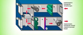
Description of the ventilation system
Air ducts are certain elements of the ventilation system that have different cross-sectional shapes and are made of different materials. To make optimal calculations, it will be necessary to take into account all the dimensions of the individual elements, as well as two additional parameters, such as the volume of air exchange and its velocity in the duct section.
Violation of the ventilation system can lead to various diseases of the respiratory system and significantly reduce the resistance of the immune system. Also, excess moisture can lead to the development of pathogenic bacteria and the appearance of fungus. Therefore, when installing ventilation in homes and institutions, the following rules apply:
Each room requires the installation of a ventilation system. It is important to observe air hygiene standards. In places with different functional purposes, different schemes of ventilation system equipment are required.
In this video, we will consider the best combination of hood and ventilation:
This is interesting: calculating the area of air ducts.
The importance of proper air exchange
The main purpose of ventilation is to create and maintain a favorable microclimate inside residential and industrial premises.
If the air exchange with the outside atmosphere is too intense, then the air inside the building will not have time to warm up, especially in the cold season. Accordingly, the premises will be cold and not humid enough.
Conversely, at a low rate of air mass renewal, we get a waterlogged, excessively warm atmosphere, which is harmful to health. In advanced cases, the appearance of fungi and mold on the walls is often observed.
A certain balance of air exchange is needed, which will allow maintaining such indicators of humidity and air temperature, which have a positive effect on human health. This is the most important task that needs to be addressed.
Air exchange depends mainly on the speed of air passing through the ventilation ducts, the cross-section of the air ducts themselves, the number of bends in the route and the length of the sections with smaller diameters of the air-conducting pipes.
All these nuances are taken into account when designing and calculating the parameters of the ventilation system.
These calculations allow you to create reliable indoor ventilation that meets all the regulatory indicators approved in the "Building codes and regulations".