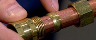
Another classification
For some, special types of elements are made. What is a special flange? These are the same hardware, but in order to make some work convenient, their design is slightly modified. They can also be welded, loose, cast, threaded. Only on them are grooves cut or projections welded. For their manufacture, first, special drawings are developed and molds are cast. Such hardware is made by order of enterprises.
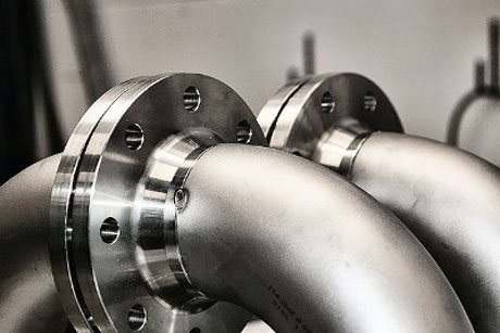
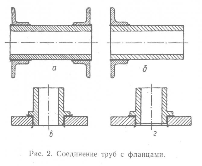
From a distance, huge and long main pipelines (gas, water, oil, steam) seem to be solid and continuous lines. But it is worth getting closer, and the joints of the pipes become noticeable. This is where the answer to the question of what flanges is. They are different: round and square, steel flat welded or steel collar flanges. But all are very important to ensure the safety of the pipelines.
Flange manufacturing
Various grades of steel are used for manufacturing: 13XFA, 20 / 09G2S, 12X18H10T, 15X5 M and others. In addition, they can be steel or stainless. The technology used is different. Manufacturers use forging, stamping, casting. For each method, special equipment and forms are used. When releasing their products, manufacturers carefully check their quality. Applying special tests in their work, employees of the Quality Control Department check them for strength and reliability. Flanges are also tested for moisture resistance.
What it is? Since they are fasteners and are involved in joining metal parts that may come into contact with water, it is important that they do not corrode. That is why waterproof metal alloys are used.
Manufacturers often cover the flange surface with an additional protective layer.
Projection height
If you look at the drawing of a steel flange, then it has several parameters, including the height of the protrusion. It is designated by the letters H and B, it can be measured in all types of products, except for the one that has a lap joint. The following should be remembered:
- models with pressure class 150 and 300 will have a protrusion height of 1.6 mm;
- models with pressure class 400, 600,900,1500 and 2000 have a shoulder height of 6.4 mm.
With ledge and depression
In the first case, suppliers and manufacturers of parts take into account the surface of the protrusion, in the second case, the surface of the protrusion is not included in the specified parameter. In part brochures, these figures may be quoted in inches, where 1.6 mm is 1/16 inch and 6.4 mm is ¼ inch.
Operating pressure
This is the pressure with which a liquid (gas, steam, etc.) is transported through the system. Consequently, the higher the working pressure in the system, the higher the strength characteristics it is necessary to choose fasteners. In turn, the required strength characteristics of the fasteners are ensured by the correct choice of material, heat treatment modes, etc. Thus, in the temperature range from -40 to + 400 ° C, and at pressures up to 100 kgf / cm2, it is recommended to use fasteners made of steel 35, while an increase in pressure up to 200 kgf / cm2 requires the use of fasteners made of steel 20X13.
Flange - photo wikipedia
Gas pipe flange connection Flanged pipe, blind flange, O-ring.
A flange (from German Flansch) is a flat piece of square, round, or other shape with holes for bolts and studs, serving for a durable (nodes of long building structures, for example, trusses, beams, etc.) and a tight connection of pipes, pipeline fittings, connecting pipes to each other, to machines, apparatus and containers, to connect shafts and other rotating parts (flange connection).
Pipes and pipeline fittings
Flanges are used in pairs (set).The design of flanges in accordance with GOST 12820-80 and GOST 12821-80 is regulated by GOST 12815-80, and it depends on the working pressure for which the flange or flange connection is calculated:
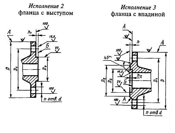
- Execution 1 - with a connecting ledge.
- Execution 2 - with a ledge.
- Execution 3 - with a hollow.
- Execution 4 - with a thorn.
- Execution 5 - with a groove.
- Execution 6 - for a lens gasket.
- Execution 7 - for oval section gasket.
- Execution 8 - with a spike for a fluoroplastic gasket.
- Execution 9 - with a groove for a fluoroplastic gasket.
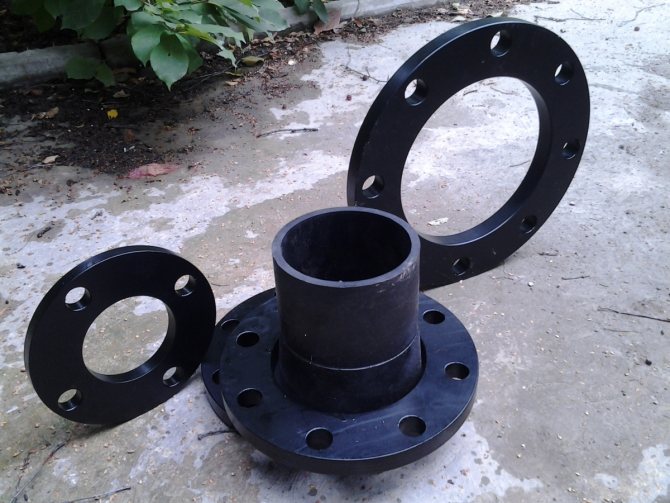
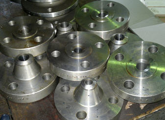
Flanges differ in types: flat, collar flanges, free on the welded ring, flanges of vessels and apparatus.
Russian standards regulate the pressure of the medium of pipelines and connecting parts, as well as on connecting flanges of fittings, connecting parts of machines, branch pipes of devices and tanks for a nominal pressure of Pу from 0.1 to 20.0 MPa (from 1 to 200 kgf / cm2)
Common flange manufacturing methods:
A productive method of manufacturing flanges is stamping of flanges in closed dies, this method makes it possible to produce flanges up to DN 700 PN 2.5 MPa. Larger diameter flanges are made from rolled rings or by CESL methods.
The production cost of flat flanges with a diameter of up to DN 2200 allows to reduce the cutting of sheet metal strips with subsequent heating and rolling on a flange bender. For this method, ultrasonic flaw detection of welded seams is mandatory. This technology allows to reduce the manufacturing cost by 50-70%, in contrast to the manufacture of flanges from a solid sheet.
Recently, in connection with the transition of many Russian enterprises to equipment manufactured according to American and German standards (ANSI / ASME, DIN / EN), there is a need for non-standard "transition" flanges. On the "transitional" flanges, the connecting surface is made according to the import standard, and the "collar" (skirt) part of the flange according to GOST (for the Russian size of pipelines).
Flat Flange Standard Sizes
The exact parameters of all standard sizes of flanges, depending on the nominal pressure, are presented in GOST 12820-80. The main sizes vary in the following ranges:
- inner hole diameter: from 10 mm to 1000 mm;
- outer diameter: from 75 mm to 1175 mm;
- greatest thickness: from 8 mm to 25 mm;
- nominal weight: from 0.25 kg to 52.58 kg.
Building construction
To connect individual small-sized building structures into whole huge structures, for example, trusses, beams, etc., bolted flange connections with the following profiles are used in the nodes of stretched structures [1]:
- open profile - T-beams, I-beams, paired corners;
- closed profile - round and square pipes.
org-wikipediya.ru
Geometry and specific gravity of products
An important parameter that determines the geometry is the nominal bore of the products. As already noted, it is denoted by the letters "DN" and has indicators from 10 to 200. This concerns the choice of the required part: when the user knows DN, all other dimensions are assigned to the flange automatically. For example, for a DN 50 model, the indent height will be 57-59; DN 80 this figure is 89-91, and DN 100 - 108-110, where the first figure indicates the inner diameter of the pipe or branch pipe, and the second indicates the outer diameter.
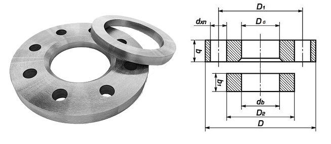
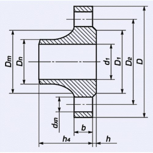
Flat flange drawing
Another important indicator is the weight of the flanges. It depends not only on volumes, sizes and height, but also on its geometry, material of manufacture. It is worth giving an example: a flange according to GOST 12820-80 with DN 100 of a flat type has a weight of 2.85 kg, while a flange of the same diameter, but a collar type according to GOST 12821-80, has a weight of 4.4 kg. This means that collar flanges are heavier than flat pieces.
Flange design features
In Russia, 3 types of connecting flanges of pipelines are used, which differ structurally. The parameters are set by GOSTs.The typical classification of steel flanges used is included in several standards:
- GOST 12820-80 is used for flat welded parts. The element is "put on" the pipe with subsequent welding fasteners. The connection is made with two seams at the joint. Installation is laborious, but provides a particularly reliable docking.
- GOST 12821-80 is used to standardize butt-welded parts (another name is collar flange). When assembling the connection, the pipe end and the collar of the main part are joined. For a strong position of the parts, welding is carried out with a single seam.
- GOST 12822-80 is used for free parts on the ring. The package includes an additional element - a ring with a diameter equal to the flange. The design is characterized by ease of installation, which is effectively used in hard-to-reach places. The connection type is used when frequent repairs are required. The peculiarity of the installation consists in welding the ring with free placement of the flange, which can be easily rotated on the pipe.
Less often, the standardization of GOSTs, adopted for threaded flanges, insulating types for subsea pipelines, and others, is used. These forms of pipe connections have a special purpose and are rare.
As part of the requirements of GOSTs, the features and parameters for each type of flanges are determined:
- Conditional pass.
It is measured in millimeters and indicates the difference in diameters between the fitting and the pipe. The parameters are not the same and are important for steel flat flanges and elements with a welded ring. For collar types of connection parts, this parameter is irrelevant. For the conditional passage, the symbol DU is used using the indices A and B, where the letter A means the diameter of the part, and under B - pipes, expressed in millimeters.
- The row of holes.
The parameter sets the difference in dimensions between the connecting holes. In some cases, different parameters of diameters expressed in millimeters are used for holes. Parts are manufactured using the default Row 2 default.
- Conditional pressure.
The indicator expresses the maximum allowable pressure that can withstand the connection without the occurrence of leaks and destruction. The parameter is influenced by the type of part, material of manufacture, diameter, width of the mating surface. Physical parameters and their influence on the maximum pressure indicator are established by GOST. When using the data, differences in the dimension of the pressure designation are taken into account.
- Working temperature.
The parameter is required to determine the pressure limit value. The physical interdependence of the pressure and temperature indicators of the transported liquid should be taken into account when passing high-temperature media through pipes. Calculated linear interpolation affects the flange connection capabilities, which are reduced with increasing operating temperatures. GOSTs establish the relationship between temperature and pressure for each type of flange.
What are flanges
They are usually used in pairs. In simple terms, it is a round or square fastener into which a pipe or other piping element is inserted. The next pipe is inserted into the other flange, after which the two fasteners are bolted together. For this, a large number of holes are provided along the outer perimeter of the part. Other types of products are put on the end of the pipe. The junction of the pipe and flange is welded. Thus, it is a connecting element for pipelines, tanks, vessels, shafts, devices, etc. For it, you also need to select the correct flange fasteners (bolts, nuts, washers, studs), the type and strength of which all directly depend on the same pressure, temperature and type of the transported medium.
Flange applications
The flange itself is not a connecting element: its task is to support the fastening bolts and ensure the tightness of this joint. As locking or connecting elements, flanges are used in communications of the housing and communal services system, the oil and chemical industry, the fuel and gas industry. A sufficiently strong and durable flanged pipe connection is also used for installation on a measuring instrument system. Various technologies and types of materials used for the manufacture of flanges make it possible to successfully operate even systems that conduct aggressive media under high pressure.
Flanged Steel Pipeline
For the installation of pipelines, discs of the same material as the main elements are usually used. This ensures uniformity of the load and insures against damage to elements as a result of temperature drops at the seams of materials with different thermal conductivity. Accordingly, the flange connection of polyethylene pipes is made in a similar unit, but for steel pipes a flange made of cast iron, aluminum, brass, bronze can be used. However, the leader is carbon style - an inexpensive, easy-to-work and practical material.
Insulating flange connections description, IFS purpose.
An insulating flange joint is a structure often used in pipelines, consisting of three flanges, between which a paronite gasket PON-B is used as an insulating sealant. The flanges are connected to each other using studs, which in turn are also isolated from the flange using fluoroplastic bushings. The design of the insulating flange connection also includes three screws for connecting electrical instruments.
An insulating flange joint is a pipeline element designed to protect the pipeline from stray currents - the so-called electrochemical corrosion. The problem of electrochemical corrosion is acute in the operation of pipelines laid underground. Stray currents, penetrating into pipes that do not have reliable insulation, are safe at the entrance, but create a dangerous anode zone at the exit, in which the metal is gradually destroyed under the influence of an electric current. Subsequently, cracks can appear in the system, which can lead to leaks and accidents in the pipeline system.
In the production of IFS, slates from steel 09g2s, gaskets and bushings made of fluoroplastic, hardware from steel 40x (according to GOST 12816) are used.
Cases when the IFS is installed:
• at the branches of pipeline sections from the main pipeline;
• near objects of probable sources of stray currents, such objects can be power substations, tram depots, repair bases;
• when installing the pipeline if its parts are made of different metals;
• to disconnect an insulated pipeline from various potentially hazardous structures or at the entrance to such facilities;
• at the outlet of the pipeline system from the supplier's territory and at its entrance to the consumer's territory;
• on vertical elevated sections of inlets and outlets of gas distribution points and gas distribution stations.
An insulating flange connection is made of two flanges manufactured in accordance with GOST 12820-80 or GOST 12821-80.
In the design in which flanges according to GOST 12820-80 are used, to ensure non-separable assembly of connections, when assembling the connections, steel pipes are welded to the flanges. This allows welding of joints without fear of overheating, loss of tightness or loss of electrical insulating properties.
General requirements for the repair of flange connections of equipment and pipelines ac
Repair or other work (including welding) with detachable joints of equipment and pipelines under pressure is not allowed, except for special operations for remote reloading of fuel assemblies without shutting down the reactor using special machines or mechanisms.
When carrying out repair work related to the decompression of equipment and pipelines, measures must be taken to exclude contamination of internal cavities or the ingress of foreign objects there.
Sealing of detachable joints of equipment and pipelines should be carried out in accordance with the production instructions using a special tool that excludes the possibility of creating unacceptable stresses in the fasteners. The tightening values for pins with controlled extraction should be formalized by acts and entered in special forms.
Repair of pipeline flanges and fittings consists of
in elimination of defects on sealing surfaces (mirrors), elimination of ovality of holes for studs and replacement of broken or defective studs with new ones.
After disassembling, the flange mirrors are cleaned of old gaskets, graphite and traces of corrosion to a metallic sheen. Cleaning is done with a scraper. The cleanliness of the surface of the mirrors is checked for the absence of scratches and strokes from the scraper.
After disassembling the flanges, be sure to change the gaskets. You cannot put an old gasket even if its condition is completely satisfactory.
Single deep defects formed on the flange mirror as a result of its destruction by a jet of steam or water in case of damage to the gasket (erosion grooves), as well as various nicks and cavities, are eliminated by electric melting with preliminary selection of the defect mechanically. The welded places are cleaned and grinded.
See the flange grinder and lapping tool on fig. 11.9
Page 1
The parallelism of the flanges is determined by measuring the gaps between the flanges along their perimeter using a feeler gauge. Checking the degree and uniformity of the tightening of the studs is carried out by measuring their elongation using a micrometer or indicator. For every 100 mm of the length of the stud, an extension from 0 03 to 0 - 15 mm is allowed. The final tightening of the nuts of all flange joints, including the joints of the covers with the valve bodies, except for the joints with metal gaskets, is carried out when the pipeline is warmed up before putting into operation at a pressure not exceeding 0 4 - 0 5 MPa. The mustache connection is welded, if necessary, in the following sequence, as shown in fig. 4.4. In this case, before the start of welding on the mustache, all the necessary tests of the product must be carried out, its operability checked and the need for cutting and re-welding is excluded. When welding a mustache, the parts to be welded must be compressed by the force specified in the technical documentation, which can be ensured either by tightening a certain number of studs with the set torque, or by using special equipment to tie two flanges. The mustache, as a rule, must be welded using the argon-arc method. Requirements for welding, control of the weld and its subsequent verification must comply with the instructions of the technical documentation for each specific product.
The parallelism of the flanges is checked using a hydraulic level or a thickness gauge. In this case, the valve must be installed with the lower flange on a horizontal support.
The parallelism of the flanges with each other and the ends of the pipes is checked with a probe. At the same time, check that there is no gap between the bearing surfaces of the flange and nuts. Under the installation conditions, the misalignment of the pipeline should not be eliminated by breaking the axis in the flange connection. When preparing a flange connection for installation, first, the flanges are rolled from the pipes, then the preservative grease is washed off and the condition of the threads on them is checked.To assemble the flange connections of the pipe wiring elements, the pipes are laid and reinforced on exposed, verified and reinforced supports. In this case, a minimum gap is left between the ends of the abutting pipes, through which the lens can be inserted. Before putting the lens into place, one or two pins are pre-inserted into the flanges. The lens wiped with a clean rag is examined and, if there is no damage on it, is installed between the two flanges using special pliers. After installing the lens, the pipes are brought together and completely clamp the lens between the ends of the pipes with studs.
The parallelism of the flanges of the device during assembly is checked with a probe.
Permissible deviations from parallelism of flanges when assembling flanged joints at an operating pressure of up to 16 tegs / sr1 should be: no more than 0 2 mm for pipes with an outer diameter of up to 108 mm and no more than 0 3 mm for pipes with a diameter over 108 mm.
Permissible deviations from parallelism of flanges when assembling flange connections at an operating pressure of up to 16 kg / cm2 should be no more than Ø 2 mm for pipes with an outer diameter of up to 108 mm and no more than Ø 3 mm for pipes with a diameter of over 108 mm.
Permissible deviations from parallelism of flanges for and assembly of flange connections at an operating pressure of up to 16 kgf / cm should be: no more than 0.2 mm for pipes with an outer diameter of up to 108 mm and no more than 0.3 mm for pipes with a diameter over 108 mm.
When assembling the oil line, it is necessary to: ensure the parallelism of the flanges by scraping or leveling them by heating the pipe to a temperature of 300 - 400 C; install Cardboard spacers with an inner diameter 2 - 3 mm larger than the inner diameter of the flange.
When assembling the flanges, the flanges must be parallel. The values of permissible deviations (in mm) for each 100 mm of the nominal diameter of the pipeline, depending on the category of the pipeline, are given below.
When assembling flange connections, deviations from the parallelism of the flanges are allowed for every 100 mm of the nominal diameter; for pipelines of the 3rd category - 0 1 mm, the 4th category - 0 2 mm. Straightening the skew of the flanges when they are connected by tightening the bolts or studs, as well as eliminating the gap by installing wedge spacers is not allowed.
Due to the need for accurate alignment of the communication elements and the parallelism of the flanges to ensure their correct tightening, the perpendicularity of the axes of the fittings or compliance with the specified angle are checked using special templates made for stiffness to the rib from sheet steel.
Flanges are widely used for reliable and tight connection of pipes, shafts, various rotating parts and components of devices and machines. The most common way to install a flange on a pipe is welded.
Insulating flange connections on the gas pipeline
Central warehouse store and assembly area
pos. Ridge, st. Sputnik / st. Kurgan, 330-37-01, 246-53-78
LLC "Stroykomplekt" is a certified manufacturer of IFS (insulating connection of gas pipelines, insulating flange connection). The certificate of conformity No. С-RU.AE56.B.00987 TP 0681219 was issued by the certification body. Valid from 06/06/2011 to 05/06/2016. ...
A special order is possible for the manufacture of components and IFS (insulating flange connection, insulating connection of gas pipelines) with DN up to 300.
IFS (insulating flange joint), insulating joint of gas pipelines) is a firmly tight connection of two sections of the pipeline, which, by means of an electrically insulating gasket and bushings, prevents the passage of electric current along the pipeline. IFS (insulating flange connection, insulating connection of gas pipelines) consists of three flanges. A paronite gasket PON-B was used between them as a sealant-insulator. The connection of the flanges is provided by pins, which are isolated from the flange by fluoroplastic bushings.Three screws are provided for connecting electrical measuring instruments in the IFS design (insulating flange connection, insulating connection of gas pipelines).
Technical characteristics:
Nominal pressure of the medium (PN) 10, 16, 25 kgf / cm2 Temperature of the medium: from -30 to 250 ° С Resistance at a voltage of 1 kV, not less than 5 MΩ
Complies with GOST 12816-80 Certificate No. ROSS RU.AYU96.B03259 dated 12.04.05 License No. AYu96.B00415 dated 07.05.01
Fig. 1 Insulating flange connection
Technical description:
IFS (insulating joint of gas pipelines, insulating flange joint) is a firmly tight connection of two sections of the pipeline, which, by means of an electrically insulating gasket and bushings, prevents the passage of electric current along the pipeline. The design of the IFS (insulating connection of gas pipelines, insulating flange connection) is shown in Fig. 1. IFS (insulating connection of gas pipelines, insulating flange connection) consists of three flanges (pos. 1 and 3). A paronite gasket PON-B (item 5) is used as a seal between them. The connection of the flanges (pos. 1 and 3) is secured by a stud (pos. 4), which is isolated from the flange (pos. 1) by a fluoroplastic bushing (pos. 2). Three screws (item 6) are provided for connecting electrical measuring instruments in the design of the IFS (insulating connection of gas pipelines, insulating flange connection).
Weld-on flange advantages
Flange connections are a kind of detachable fastening method. The use of metal discs allows, if necessary, to disassemble the pipeline section for routine maintenance. Welded flanges, in contrast to threaded counterparts, provide higher reliability of connections and are an economically viable way of connecting pipes to other products.
Installation of flanged discs and their fastening to the pipe can be carried out by:
- manual arc welding;
- semi-automatic.
The best quality result is provided by resistance welding. Flange connection is an available mounting method. A wide variety of standards and materials from which flanges are made allows you to select the best options for a high-quality detachable connection. Welding flanges are used everywhere in all areas of industrial production.
Flange pressure classes
Parts manufactured according to Asme (Asni) standards are always characterized by a number of parameters. One of these parameters is the nominal pressure. In this case, the diameter of the product must correspond to its pressure in accordance with the established samples. The nominal diameter is indicated by a combination of the letters "ДУ" or "DN", after which there is a number that characterizes the diameter itself. Nominal pressure is measured in "RU" or "PN".
Flange drawing with various designations
The pressure classes of the American system correspond to the conversion to MPa:
- 150 psi - 1.03 MPa;
- 300 psi - 2.07 MPa;
- 400 psi - 2.76 MPa;
- 600 psi - 4.14 MPa;
- 900 psi - 6.21 MPa;
- 1500 psi - 10.34 MPa;
- 2000 psi - 13.79 MPa;
- 3000 psi - 20.68 MPa.
Translated from MPa, each class will indicate the flange pressure in kgf / cm². The pressure class determines where the selected part will be used.
Joint gaskets
When choosing a gasket for a flange connection, it is imperative to take into account the nature of the environment with which the pipeline will work. The following parameters are also taken into account: temperature, pressure, environment. The flange seal can be movable or fixed. Depending on that, low-melting seals, paronite, rubber, and other materials are used. For flat flanges, they are sealed using corrugated or metal gaskets, which are softly padded.
A very important parameter when connecting a flange to a pipeline is the force with which the gasket is compressed. Typically, it is measured in hundreds of kilonewtons.
If we talk about what dimensions the gaskets have, then we note that they are designed to ensure the assembly of the unit, taking into account the surfaces that the seal itself occupies. When centering the entire assembly, there should be no gasket extrusion. Additional flange constructions can be used to better secure the gasket to the flange. In particular, a tenon and a groove on two surfaces opposite to each other may be some kind of lock. It not only protects the gasket, but also increases the sealing of the joint.
Flange varieties
On the official website of our company, a virtual catalog is presented, in which all sold fittings are placed according to thematic sections. In it, a separate place is allocated to flanges, which differ from each other not only in modification, but also in the following parameters:
- by the method of installation;
- by scope of application;
- on the materials that were used in their manufacture;
- by operating parameters.
Flat and collar flanges are available to our customers today. They are actively used by business entities specializing in the production and extraction of minerals.
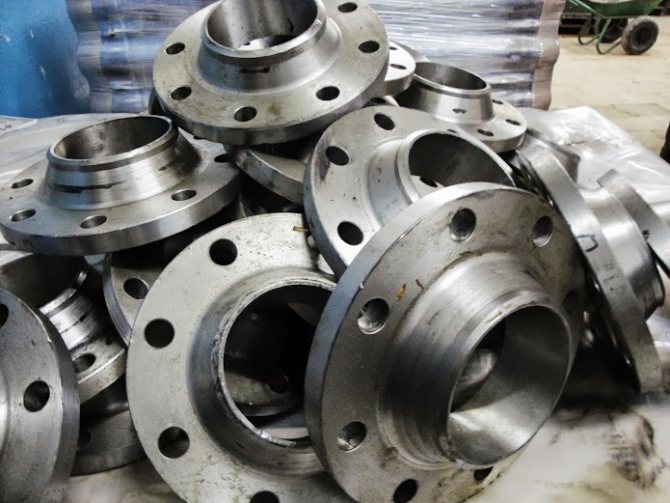
Features of collar flanges
In the process of manufacturing collar flanges, manufacturers use high-strength steel of various markings as the main raw material. Finished products are capable of withstanding a pressure of 1-10 MPa and can be operated at various operating temperatures, therefore, they are classified as follows:
- steel grade No. 20 and 25 - the flange will perform the functions assigned to it at temperatures up to - 30 degrees;
- structural steel grades - flanges can be operated at extremely low temperatures up to - 70 degrees.
The design features of collar flanges include the presence of truncated protrusions on their surface. The function of this element is to provide a hermetic pipe connection.
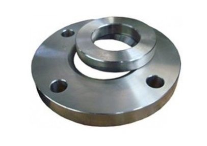
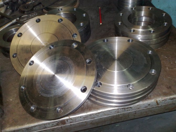
Technical capabilities of flat flanges
Flat flanges are manufactured in a production environment with high-tech equipment and modern technical standards. Finished products fully comply with state norms and standards, and are sold for sale along with accompanying documentation and relevant certificates. The main purpose of flat flanges is to provide detachable pipe connections during the installation of pipelines and control units for shut-off valves and systems. It should be noted that, despite the possibility of quick dismantling of such flanges, their use guarantees the most tight connection for engineering communications. These fittings are capable of performing their functions for many decades at a wide temperature range: from + 300 to - 70 degrees. Visitors to the website of the TK Engineering company have access to various modifications of flat steel flanges, which are made of the following types:
- heat resistant;
- stainless;
- alloyed, etc.
We also offer:
Flat steel flanges
Flange connection functions and features
What is a pipe flange? This is a flat steel plate of an annular (less often square or rectangular) shape. In the middle there is a hole on it where the end section of the pipe is inserted. The edges of the plate are equipped with several holes located at the same distance from each other: bolts or pins are threaded through them, and clamped with nuts.
Flanged pipe connections are a good alternative to welding and couplings, with the possibility of quick assembly and disassembly. The installation is accompanied by welding of the end part and the through-flange passage to each other. Further, the two plates are pulled together with each other using keys of the appropriate size. For large flanges, pipe arms are required when tightening.
To make the docking airtight, rubber or fluoroplastic sealing gaskets are used. In addition, if there is a need to overlap certain sections of the pipeline for repairs, it is envisaged to use special plugs called seals. In this way, pipelines can be connected to various devices and technological tanks: these are mainly heat exchangers. For this, the end of the pipe is equipped with a welded flange that is connected to the intake pipe of the unit.
Flanges by type of application are divided into the following types:
- Separate sections of pipelines joining each other. Designed for a pressure of 0.1 - 20 MPa (GOST # 12815).
- Providing the possibility of joining pipelines with equipment and containers (GOST # 28759).
To calculate flange connections, there is a special literature with corresponding tables.
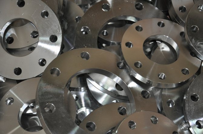
What are they made of?
Flanges are made of steel. Depending on the working pressure, temperature and type of the transported medium (steam, gas, oil, water), they are produced either from a special alloy or from conventional grades of carbon and stainless steel.
Main types:
- the most common are conventional flat weld flanges;
- steel collar flanges are more durable and comfortable;
- for installation in hard-to-reach places, a free flange on the welded ring is most often used;
- non-standard flanges, which are made according to individual drawings for a specific order.
Consider the most popular product options.
Flange production: technology and materials
Flanges are typically made from low alloy, carbon steel that resists corrosion. If cast iron is used, the following grades are used: SCh15, SCh20, malleable cast iron KCh30-6; high strength cast iron VCh 40 and VCh 45.
As for flanges of type 01-04, sheet metal can be used for their production. In the case when the seams are welded along the entire section, the flanges can also be made welded. However, for Type 11 products, sheet metal is not used. Here, stamped blanks or forgings are used.
Flanges, which are made by hot metal forging, stamping, rolling, meet modern operational requirements as much as possible. It is best when, after hot stamping, the products undergo additional thermal hardening.
Cast iron flanges are less deformed. However, they must be handled with care, given that cast iron is a fragile material. For example, when tightening fasteners, you must observe the force threshold so as not to break the cast iron.
Flange types
So, a flange is, first of all, a hardware. Depending on the application, these parts can be flat, collar, free. The design is not much different. The collar flanges have a small cone-like projection. It is often called a collar. This type of flange is used when parts need to be butt welded. This protrusion helps to tightly connect the pipe fittings together. They are also necessary when pipelines are supplied to tanks or other technical equipment. The main advantage of these flanges is that they can be used several times. These hardware are made of durable materials, and this allows them to be used in work where the temperature ranges from -253 to +600 degrees Celsius.
What is a flat flange? It is a hardware that resembles a flat disc with holes. It is used when you need to connect parts of fittings, shafts, vessels, pipelines, devices and the like. With this element, you can tightly fasten parts of the pipelines.
Loose flange - what is it? This view is not much different from the ones listed above. It consists of two parts: a regular flange and a ring
It is important that they are made of the same material and have the same diameter and pressure. They are used where the work is most difficult, where installation is difficult.
Due to the two parts, the connection will be tight and strong. First, a conventional flange is connected (it is welded), and then the other ring can then be safely turned during operation.
The degree of tightness of the connections
The most important requirement for the connection of the pipeline with the fittings is tightness. It should be noted that the loss of sealing of the flange connections is not due to objective flaws, but due to untimely and negligent maintenance. To ensure that the connections on the pipeline are always tight, it is important to regularly tighten the flange retainers. Of course, we must not forget about the gaskets.
Reliability, the possibility of multiple installation, application at various temperature conditions - all this and not only refers to the advantages of the connection in question. It can be used to connect pipelines of almost any diameter (from 10 to 1800 mm).
Note that a huge number of flange varieties does not confuse specialists. On the contrary, they have many possibilities for creating quality connections. Various design options, standard products, general technical requirements allow us to perform work at the highest level.
Today in Russia there is a standard GOST 33259-2015 Valve flanges, connections with a nominal pressure of up to PN250. Dimensions, designs, general technical requirements. This document replaces the GOSTs that were previously used.
In particular, GOST 33259-2015 lists 6 types of flanges. The first four items have the following name: steel, flat flange.
As for steel flat flanges for welding, they are put on the pipe, and then welded to it.
Loose flanges are characterized by the fact that the diameter on the inner section is larger than on the pipe in the outer diameter. Consequently, welding to the pipeline is easily performed, which means that installation becomes easy.
A flat steel flange on a welded ring, in addition to the flange itself, has a ring that coincides with the flange in terms of the nominal diameter. By welding, you can fix not only the ring, but also leave the flange free. This method of fixing is useful when installing flange connections in places where it is very difficult to reach, with the need for frequent replacement and repair of valves.
To use steel, flat flanges of the free type, the pipe end must be prepared on the flange. It is deformed to a flat, stubborn surface. These flanges are best used on non-ferrous pipelines.
When steel, flat flanges of a free type are installed on a clamp, a clamp is placed under welding instead of a closed ring.
The steel butt joint is joined by a single weld seam that butt-joints the pipe end to the collar of the flange. Its inner diameter is exactly the same as that of the pipe.
Based on GOST 33259-2015, for types 01.02, 11 and 21, 2 series of sizes are provided. The first row is considered preferred.
How is a flanged connection made?
When it is necessary to connect two parts of the pipeline, welding of a steel flange to the pipe is used. Such a fixation is called a flange connection and in the future it makes it possible to disassemble the pipeline in order to carry out repairs. To understand how the assembly takes place, you need to consider the process in detail:
- To join two elements, flat parts are used that have a hole in the center where the end of the pipe is inserted.
- There are holes along the perimeter of the ring - fasteners are inserted into them: bolts or studs with nuts.
- The connection will be detachable so that it is sealed using gaskets. A flange connection is designed to join two pipes or connect a pipe to a tank equipped with a flanged inlet pipe.
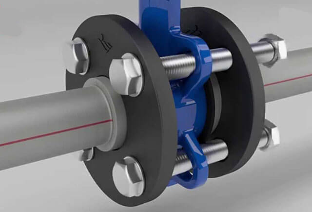
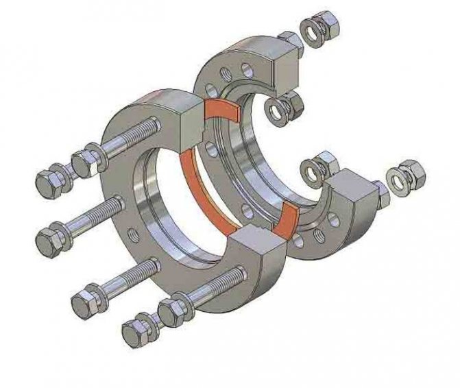
Illustrative example of a flange connection
The flange can be made with your own hands - such a detail is perfect for a sharpener for a machine for sharpening objects.
Compound Manufacturing Tools
To independently make the connection of two pipe parts, you need to prepare tools.Basically, this is equipment designed for tightening bolted joints around the circumference of the flanges:
- manual key;
- spanner key;
- pneumatic impact wrench;
- hydraulic torque wrench;
- bolt tensioner hydraulic type.
Docking on pipes
In addition, a special lubricant will be required, which is applied to both surfaces to avoid friction between parts and ensure lightness of the torque. The sequence of work is simple: first, tighten the first bolt, then proceed to tighten the one that is diagonally 180 degrees from the first. Next, they go to the bolt located at an angle of 90 degrees from the second, and from it to the opposite one.
Tips from the masters
There are a number of useful recommendations from professional craftsmen who will help you cope with a flange connection the first time:
- If the parts have 4 holes, then the bolts must be tightened crosswise.
- The surface of the structure must be degreased and checked for corrosion and rust.
- It is recommended to use only new gaskets, and they must be installed strictly in the center.
- The tightening torque of the bolts must be uniform - this is the only way to ensure a reliable and tight flange connection.
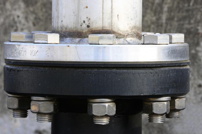
Connected pipes with flanges
In order to remove the flange in the future, special machines are used that help to bore it and loosen the bolts. It is difficult to remove parts manually, therefore pneumatic tools are used.
Connecting pipes with flanges is a convenient and reliable way of joining two parts. It helps in the future to carry out the repair of the pipeline by removing the connecting elements, while welding will not allow this procedure to be carried out. It is selected in exact accordance with the working conditions, temperature and pipe diameter.


Tools
51 votes
+
Voice for!
—
Against!
The reliability of any system depends on the reliability of the weakest link in the system. Welded joints of steel pipes are reliable and are used in most cases. But situations arise in which the use of a welded joint is impossible. Connecting various fittings, providing a collapsible connection, the possibility of preventing and repairing pipe fittings as well as working units of units, connecting dissimilar pipes: cast iron-plastic, cast iron-steel, steel-plastic, steel-asbestos cement, plastic-asbestos cement and the solution of many more technological problems. A flange connection should ensure the reliability and durability of the operation of such connections. In general, flange designs include a pair of flanges and a gasket and rings that are bolted or studded together.
Content
- Flanges - general characteristics of the video
- Flange design features
- Flange designation
- Flange gaskets
- Tightening flange connections video
Flanges - general characteristics
For the unification of products and the possibility of using these products in different countries of the world without additional processing, a clear classification of flange connections has been introduced. Sometimes the same flange in different classifications will have different designations.
The main classifications used in the world:
- GOST - the standard adopted in the USSR, and acting in the post-Soviet space;
- DIN - German standard valid in Europe;
- ANSI / ASME is an American standard valid in the USA, Japan and Australia.
There are standards conversion tables that indicate which standard a particular flange meets.
Various materials are used for the manufacture of flanges:
- cast iron;
- malleable cast iron;
- carbon steels;
- stainless steels;
- alloy steels;
- polypropylene.
Polypropylene flanges have become widespread in the last decade. They are mainly used for the installation of non-pressure systems, connecting PE pipes with metal pipes, connecting pipe fittings on which a flange mount is installed. Flanges such as metal flanges are made by casting or stamping.
Flanges are also divided by types:
- flat (GOST 12820-81);
- collar (GOST 12821-81);
- loose flanges on the welded ring (GOST 12822-80);
- flanges for vessels and apparatus (GOST 28759.2-90);
- ring plug (GOST 12836-80).
It is allowed to manufacture square flanges that have at least 4 holes for bolts or studs. Such flanges can be used on systems with a maximum pressure of not more than 4.0 MPa.
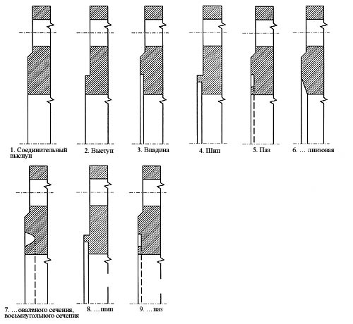
According to the nomenclature and, accordingly, GOST 12815-80, flanges of fittings and pipe fittings have nine basic versions of the sealing surface:
- isp. 1 - with a connecting ledge, the most common version of flanges, has a special connecting ledge in the form of a chamfer at an angle of 45 °
- isp. 2 - similar in design to the previous model, only the connecting ledge goes at an angle of 90 °;
- isp. 3 - with a depression on the inside and a protrusion on the outside at an angle of 45 °;
- isp. 4 - with a thorn;
- isp. 5 - with a groove in the form of an annular sample;
- isp. 6 - under the lens gasket, a chamfer is selected from the inside;
- isp. 7 - for an oval-section gasket, an annular sample in the form from the end side;
- isp. 8 - with a spike for a fluoroplastic gasket;
- isp. 9 - with a groove for a fluoroplastic gasket.
Flanges of vessels and apparatuses have their own performance requirements indicated in GOST 28759.2-90, and for flat welded flanges - in GOST 28759.390
Flange design features
Flanges, like any pipe or shut-off valve, have several design features. When choosing and decoding the designation of flanges, these features must be known.
Conditional pass
The nominal diameter of the flange is the inner diameter of the pipe, fitting or shut-off valve to which the flange is welded. It is taken on the basis of only the nominal pipe diameter.
For flat welded flanges with a nominal bore of 100, 125, 150, depending on the version, the letter (A, B, C) is indicated - the outer diameter of the pipe depends on it, if the letter is not indicated, the letter A is considered by default.
Rows
All geometrical dimensions of the flange will depend on the nominal size. The same flange with the same nominal bore can be made in two ways - row1 and row2. They differ in different center distances between the connecting holes, as well as, in some cases, different diameters of the connecting holes. By default, flanges are made in row 2.
Pressure
An important property of a flange connection is the ability to maintain system pressure without leaks and system destruction. This indicator is designated as conditional pressure. The nominal pressure indicator depends on the geometric dimensions of the flange, material of manufacture, design, and sealing gasket.
Important: When ordering flanges, remember that there are different dimensions of pressure: in kgf / cm2, Pa (MPa), atm., Bar. Therefore, it is necessary to indicate exactly what pressure this product should be designed for.
Temperature
The operating fluid temperature will become the flange temperature, it should be noted that the pressure and temperature parameters are interdependent. As the temperature rises, the maximum pressure at which the flange joint operates will drop. Dependency can be expressed by linear interpolation. The relationship between operating temperature and pressure for each flange is given in special tables and GOSTs.
Flange designation
Each of the types of flanges has its own specific designation, we will consider each of them.
Flat weld flanges
Let's take an example of the designation of flat welded flanges:
Flange 1-65-25 09G2S GOST 12821-80
Flat welded flange version 1 with nominal bore (DN) - 65mm, designed for nominal pressure of 25kgf / cm2, made of steel 09G2S in accordance with GOST 12821-80.
When choosing a flange for a fluoroplastic gasket after the number Du, indicate the letter F.
Collar flanges
Flange 1-1000-100 st. 12x18n10t GOST 12821-80
Designates a flange of version 1, with a nominal bore of 1000, designed for a pressure of 100 kgf / cm2, made of steel 12x18n10t, which is a structural stainless steel.
For square flanges, the name is additionally indicated - a square flange.
As well as in flat flanges, when using a fluoroplastic gasket, indicate the letter F.
Loose flanges on the weld ring
The designation of loose flanges as well as flat flanges is slightly different. Since this product uses a welded ring, the flange designation also includes a ring designation, for example:
Flange 50-6 ST20 GOST 12822-80
Ring 1-50-6 ST 35 GOST 12822-80
Here: 50 - nominal bore, nominal pressure 6 kgf / cm2, the flange is made of steel st20, the ring is made of steel st35.
For conditional passage 100, 125, 150, you must also indicate the letter (A, B, B), by default - A.
Flange gaskets
Sealing a unit or joint under excessive pressure, often in an aggressive environment, plays an important role in the design of a flange joint.
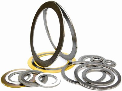
Depending on the type of flange or yoke used, the design, pressure, temperature, chemical properties of the medium, the following are used as sealing gaskets:
- KShch (7338-77) - technical acid-base rubber;
- MB (7338-77) - oil and petrol resistant rubber;
- Т (7338-77) - technical heat-resistant rubber;
- PON (481-80) - general purpose paronite;
- PMB (481-80) - oil and petrol resistant paronite;
- Asbestos cardboard;
- Fluoroplast-4.
Tightening flange connections
Tightening flange connections is the key to flange mounting. To achieve maximum sealing, all parts need to be accurate.
Preparing the elements
Clean and degrease the flange surfaces, check for scratches, dents and dents. Inspect for corrosion of the flange itself and of the fasteners - bolts and nuts. Remove burrs from the thread, you can also "drive" each bolt and nut along the thread. Lubricate the bolt threads or studs. Prepare and install the gasket. Make sure it is installed correctly, it should be centered.
Important: Do not use old gaskets, if it is not possible to replace the gasket, several old gaskets can be installed.
Tightening sequence
The correct bolt tightening order will ensure that the flange is securely and correctly seated. To do this, lightly shade the first bolt, select the next bolt from the opposite side, tighten also slightly. The third bolt you are tightening is a quarter turn (90 °) behind the first, or close to this angle. The fourth is opposite the third. Continue the sequence until all bolts are tightened. When tightening flanges with a 4-bolt attachment, use a criss-cross technique.
Torque
To obtain the most leakproof connection, the bolts must have the correct tightening torque. The tightening stress must be evenly distributed over the flange. During tightening, a tensile force acts on the bolt opposite to the tightening force of the joint. Excessive tightening force can strip the threads on the bolt or break the bolt itself.
Different tightening techniques are used to adjust the tightening torque:
- hydraulic tensioning mechanism;
- hydraulic torque wrench;
- pneumatic impact wrench;
- manual torque wrench.
As a last resort, you can use a hand tighten, but it is better for a professional to work in this way.
Regardless of the selected tightening method, the torque with which the nuts are tightened must meet the product specifications.
After installing the flange and starting the system in the first 24 hours of operation, a loss of tightening torque of up to 10% is possible. This is inherent in any bolted connection due to vibration, shrinkage of the gasket, and temperature changes.
After a day or two, additionally tighten the threaded connections to the set torque, according to the specification.
What the part is made of
In industry, steel flanges are used, but the steel from which the part is made also varies. The marking of the steel flanges will determine in what conditions it is best to use a given part:
- Steel 20 is the most used raw material. This is carbon steel, parts made of it are used to assemble fittings on highways, where the external temperature is not lower than –40 degrees, and the internal indicators are not higher than +475 degrees.
- Steel 09g2s - steel from alloys of nickel, chromium and molybdenum, intended for welding. Products made of this material can be used at an external temperature of –70 degrees.
- 12Х18Н10Т - cryogenic steel. Parts made of this material can be used in aggressive environments, for example, with alkalis and acids. The permissible temperature is from - 196 degrees to +350 degrees.
- 10Х17Н13М2Т - corrosion-resistant ordinary steel. Fasteners from it are used in particularly extreme conditions, because it remains resistant to stress corrosion. Working temperatures from -196 to +600 degrees.
- 15Х5М - low-alloy heat-resistant steel. Such products have high resistance to oxidation at temperatures of + 600-650 degrees.
These brands are the most used, however, manufacturers use other raw materials besides them. There are polypropylene models - they are designed for joining polypropylene pipes with metal valves. The operating temperature of such a material is much lower - +80 degrees. A collar for a flange can be sold to them in a set - a special part for creating a flange connection made of polypropylene.
Polypropylene flange
In addition to steel and propylene, two types of cast iron are used - malleable and gray. Parts made of ductile iron are used at operating temperatures from -30 to +400 degrees, and from gray cast iron - at temperatures from -15 to +300 degrees.
Flanges
Manufacturer: LLC "Liskimontazhkonstruktsiya"
The most common type of connection of shut-off, control valves, filters and other process equipment to pipelines is a flange connection. Advantages: the possibility of multiple mounting and dismounting on the pipeline, the reliability of sealing joints and the possibility of tightening them, great strength and suitability for a very wide range of pressures and passages.
Disadvantages: the possibility of loosening the tightening and loss of tightness over time, significant laboriousness of assembly and disassembly, large dimensions and weight, especially with an increase in pressure and nominal bore.
Flange connections of pipelines and fittings for nominal pressures from PN 1 to PN 200 are standardized by GOST 54432-2011.
Flanges used for connecting fittings, equipment and instruments to gas pipelines must comply with GOST 54432-2011.
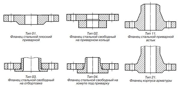
Fig. 1.1. Flange types
Note. Flanges of type 21 are an element of fittings, equipment or pipe fittings and are not manufactured separately.
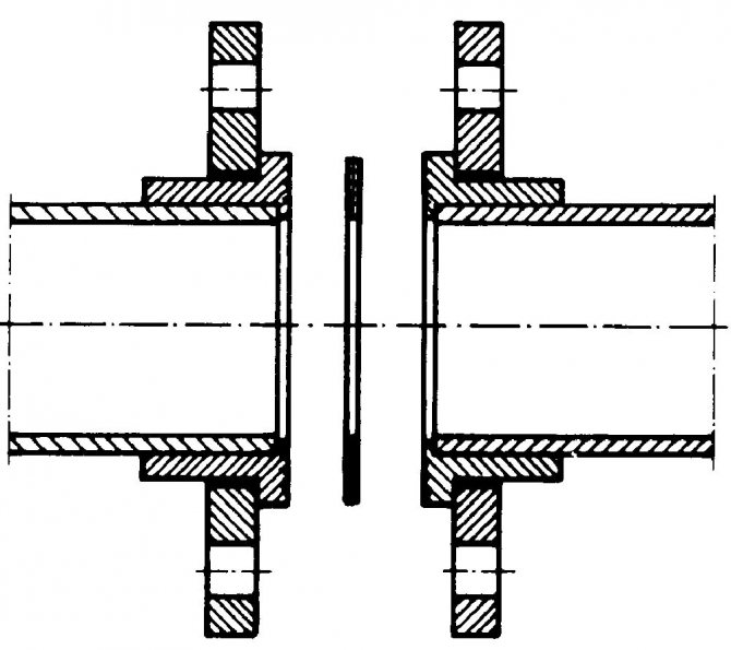
Flange types are shown in fig. 1.1, and the design of the sealing surfaces in Fig. 1.2.
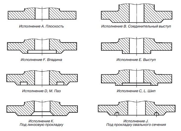
Fig. 1.2. Sealing surface designs
Note. Sealing surfaces of versions L and M are used for fluoroplastic gaskets.
The applicability of flanges with nominal diameter DN depending on the nominal pressure PN for each type of flange is given in tab. 1.1
Table 1.1. Flange applicability
| Flange type | Nominal pressure PN, kgf / cm2 | Nominal diameter DN | ||||||||||||||||||||||||||
| DN 10 | DN 15 | DN 20 | DN 25 | DN 32 | DN 40 | DN 50 | DN 65 | DN 80 | DN 100 | DN 125 | DN 150 | DN 200 | DN 250 | DN 300 | DN 350 | DN 400 | DN 450 | DN 500 | DN 550 | DN 600 | DN 700 | DN 800 | DN 900 | DN 1000 | DN 1200 | DN 1400 | ||
| Type 01.Steel flat welded flanges | PN 1 | X | X | X | X | X | X | X | X | X | X | X | X | X | X | X | X | X | X | X | X | X | X | X | X | X | X | |
| PN 2.5 | X | X | X | X | X | X | X | X | X | X | X | X | X | X | X | X | X | X | X | X | X | X | X | X | X | X | ||
| PN 6 | X | X | X | X | X | X | X | X | X | X | X | X | X | X | X | X | X | X | X | X | X | X | X | X | X | X | ||
| PN 10 | X | X | X | X | X | X | X | X | X | X | X | X | X | X | X | X | X | X | X | X | X | X | X | X | X | X | ||
| PN 16 | X | X | X | X | X | X | X | X | X | X | X | X | X | X | X | X | X | X | X | X | X | X | X | X | X | |||
| PN 20 | X | X | X | X | X | X | X | X | X | X | X | X | X | X | X | X | X | X | X | X | ||||||||
| PN 25 | X | X | X | X | X | X | X | X | X | X | X | X | X | X | X | X | X | X | X | X | X | X | ||||||
| Type 02. Loose steel flanges on the welding ring | PN 1 | X | X | X | X | X | X | X | X | X | X | X | X | X | X | X | X | X | X | X | ||||||||
| PN 2.5 | X | X | X | X | X | X | X | X | X | X | X | X | X | X | X | X | X | X | X | |||||||||
| PN 6 | X | X | X | X | X | X | X | X | X | X | X | X | X | X | X | X | X | X | X | X | ||||||||
| PN 10 | X | X | X | X | X | X | X | X | X | X | X | X | X | X | X | X | X | X | X | X | ||||||||
| PN 16 | X | X | X | X | X | X | X | X | X | X | X | X | X | X | X | X | X | X | X | X | ||||||||
| PN 25 | X | X | X | X | X | X | X | X | X | X | X | X | X | X | X | X | X | X | X | X | ||||||||
| Type 03 Type 04. Loose steel flanges on the flange and on the clamp for welding | PN 6 | X | X | X | X | X | X | X | X | X | X | X | X | X | X | X | X | X | X | X | X | |||||||
| PN 10 | X | X | X | X | X | X | X | X | X | X | X | X | X | X | X | X | X | X | X | X | ||||||||
| PN 16 | X | X | X | X | X | X | X | X | X | X | X | X | X | X | X | X | X | X | X | X | ||||||||
| PN 25 | X | X | X | X | X | X | X | X | X | X | X | X | X | X | X | X | X | X | X | X | ||||||||
| Type 11. Steel butt weld flanges | PN 1 | X | X | X | X | X | X | X | X | X | X | X | X | X | X | X | X | X | X | X | X | X | X | X | X | X | X | |
| PN 2.5 | X | X | X | X | X | X | X | X | X | X | X | X | X | X | X | X | X | X | X | X | X | X | X | X | X | X | ||
| PN 6 | X | X | X | X | X | X | X | X | X | X | X | X | X | X | X | X | X | X | X | X | X | X | X | X | X | X | ||
| PN 10 | X | X | X | X | X | X | X | X | X | X | X | X | X | X | X | X | X | X | X | X | X | X | X | X | X | X | ||
| PN 16 | X | X | X | X | X | X | X | X | X | X | X | X | X | X | X | X | X | X | X | X | X | X | X | X | X | X | ||
| PN 20 | X | X | X | X | X | X | X | X | X | X | X | X | X | X | X | X | X | X | X | X | ||||||||
| PN 25 | X | X | X | X | X | X | X | X | X | X | X | X | X | X | X | X | X | X | X | X | X | X | X | X | X | |||
| Type 21. Cast steel flanges (reinforcing bodies) | PN 6 | X | X | X | X | X | X | X | X | X | X | X | X | X | X | X | X | X | X | X | X | X | X | X | X | X | X | |
| PN 10 | X | X | X | X | X | X | X | X | X | X | X | X | X | X | X | X | X | X | X | X | X | X | X | X | X | X | ||
| PN 16 | X | X | X | X | X | X | X | X | X | X | X | X | X | X | X | X | X | X | X | X | X | X | X | X | X | X | ||
| PN 20 | X | X | X | X | X | X | X | X | X | X | X | X | X | X | X | X | X | X | X | X | ||||||||
| PN 25 | X | X | X | X | X | X | X | X | X | X | X | X | X | X | X | X | X | X | X | X | X | X | X | X | X | X | ||
In fig. 1.3 and in tab. 1.2 shows the dimensions of the flange sealing surface depending on the version.
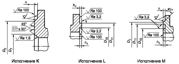
Fig. 1.3. Dimensions of sealing surfaces of flanges for nominal pressure PN 10, PN 16, PN 25
Table 1.2. Dimensions of flange sealing surfaces for nominal pressure PN1, PN2.5, PN6, PN10, PN16, PN25 in accordance with GOST 54432-2011
| DN | PN, kgf / cm2 | D2 | D3 | D4 | D5 | D6 | D7 | D8 | D9 | D10 | D11 | b2 | h | h1 | h2 | h3 | h4 | h5 | ||||
| Row 1 | Row 2 | Row 1 | Row 2 | Row 1 | Row 2 | Row 1 | Row 2 | |||||||||||||||
| DN 10 | PN 1 | 33 | 19 | — | — | 18 | — | 30 | — | — | — | — | 18 | 30 | — | 2 | 4 | 3 | — | 4 | 3 | |
| PN 2.5 | 24 | 29 | 34 | 23 | 35 | |||||||||||||||||
| PN 6 | ||||||||||||||||||||||
| PN 10 | 41 | 24 | 34 | 23 | 35 | 23 | 35 | |||||||||||||||
| PN 16 | ||||||||||||||||||||||
| PN 25 | ||||||||||||||||||||||
| DN 15 | PN 1 | 38 | 23 | — | 33 | — | 22 | — | 34 | — | — | — | — | 22 | 34 | — | 2 | 4 | 3 | — | 4 | 3 |
| PN 2.5 | 29 | 39 | 28 | 40 | ||||||||||||||||||
| PN 6 | ||||||||||||||||||||||
| PN 10 | 46 | 29 | 39 | 28 | 40 | 28 | 40 | |||||||||||||||
| PN 16 | ||||||||||||||||||||||
| PN 25 | ||||||||||||||||||||||
| DN 20 | PN 1 | 48 | 33 | — | 43 | — | 32 | — | 44 | — | — | — | — | 32 | 44 | — | 2 | 4 | 3 | — | 4 | 3 |
| PN 2.5 | 36 | 50 | 35 | 51 | ||||||||||||||||||
| PN 6 | ||||||||||||||||||||||
| PN 10 | 56 | 36 | 50 | 35 | 51 | 35 | 51 | |||||||||||||||
| PN 16 | ||||||||||||||||||||||
| PN 25 | ||||||||||||||||||||||
| DN 25 | PN 1 | 58 | 41 | — | 51 | — | 40 | — | 52 | — | — | — | — | 40 | 52 | — | 2 | 4 | 3 | — | 4 | 3 |
| PN 2.5 | 43 | 57 | 42 | 58 | ||||||||||||||||||
| PN 6 | ||||||||||||||||||||||
| PN 10 | 65 | 43 | 57 | 42 | 58 | 42 | 58 | |||||||||||||||
| PN 16 | ||||||||||||||||||||||
| PN 25 | ||||||||||||||||||||||
| DN 32 | PN 1 | 69 | 49 | — | 59 | — | 48 | — | 60 | — | — | — | — | 48 | 60 | — | 2 | 4 | 3 | — | 4 | 3 |
| PN 2.5 | 51 | 65 | 50 | 66 | ||||||||||||||||||
| PN 6 | ||||||||||||||||||||||
| PN 10 | 76 | 51 | 65 | 50 | 66 | 50 | 66 | |||||||||||||||
| PN 16 | ||||||||||||||||||||||
| PN 25 | ||||||||||||||||||||||
| DN 40 | PN 1 | 78 | 55 | — | 69 | — | 54 | — | 70 | — | — | — | — | 54 | 70 | — | 2 | 4 | 3 | — | 4 | 3 |
| PN 2.5 | 61 | 75 | 60 | 76 | ||||||||||||||||||
| PN 6 | ||||||||||||||||||||||
| PN 10 | 84 | 61 | 75 | 60 | 76 | 60 | 76 | |||||||||||||||
| PN 16 | ||||||||||||||||||||||
| PN 25 | ||||||||||||||||||||||
| DN 50 | PN 1 | 88 | 66 | — | 80 | — | 65 | — | 81 | — | — | — | — | 65 | 81 | — | 2 | 4 | 3 | — | 4 | 3 |
| PN 2.5 | 73 | 87 | 72 | 88 | ||||||||||||||||||
| PN 6 | ||||||||||||||||||||||
| PN 10 | 99 | 73 | 87 | 72 | 88 | 72 | 88 | |||||||||||||||
| PN 16 | ||||||||||||||||||||||
| PN 25 | ||||||||||||||||||||||
| DN 65 | PN 1 | 108 | 86 | — | 100 | — | 85 | — | 101 | — | — | — | — | 85 | 101 | — | 2 | 4 | 3 | — | 4 | 3 |
| PN 2.5 | 95 | 109 | 94 | 110 | ||||||||||||||||||
| PN 6 | ||||||||||||||||||||||
| PN 10 | 118 | 95 | 109 | 94 | 110 | 94 | 110 | |||||||||||||||
| PN 16 | ||||||||||||||||||||||
| PN 25 | ||||||||||||||||||||||
| DN 80 | PN 1 | 124 | 101 | — | 115 | — | 100 | — | 116 | — | — | — | — | 100 | 116 | — | 2 | 4 | 3 | — | 4 | 3 |
| PN 2.5 | 106 | 120 | 105 | 121 | ||||||||||||||||||
| PN 6 | ||||||||||||||||||||||
| PN 10 | 132 | 106 | 120 | 105 | 121 | 105 | 121 | |||||||||||||||
| PN 16 | ||||||||||||||||||||||
| PN 25 | ||||||||||||||||||||||
| DN 100 | PN 1 | 144 | 117 | — | 137 | — | 116 | — | 138 | — | — | — | — | 116 | 138 | — | 2 | 4,5 | 3,5 | — | 6 | 5 |
| PN 2.5 | 129 | 149 | 128 | 150 | ||||||||||||||||||
| PN 6 | ||||||||||||||||||||||
| PN 10 | 156 | 129 | 149 | 128 | 150 | 128 | 150 | |||||||||||||||
| PN 16 | ||||||||||||||||||||||
| PN 25 | ||||||||||||||||||||||
| DN 125 | PN 1 | 174 | 146 | — | 166 | — | 145 | — | 167 | — | — | — | — | 145 | 167 | — | 2 | 4,5 | 3,5 | — | 6 | 5 |
| PN 2.5 | 155 | 175 | 154 | 176 | ||||||||||||||||||
| PN 6 | ||||||||||||||||||||||
| PN 10 | 184 | 155 | 175 | 154 | 176 | 154 | 176 | |||||||||||||||
| PN 16 | ||||||||||||||||||||||
| PN 25 | ||||||||||||||||||||||
| DN 150 | PN 1 | 199 | 171 | — | 191 | — | 170 | — | 192 | — | — | — | — | 170 | 192 | — | 2 | 4,5 | 3,5 | — | 6 | 5 |
| PN 2.5 | 183 | 203 | 182 | 204 | ||||||||||||||||||
| PN 6 | ||||||||||||||||||||||
| PN 10 | 211 | 183 | 203 | 182 | 204 | 182 | 204 | |||||||||||||||
| PN 16 | ||||||||||||||||||||||
| PN 25 | ||||||||||||||||||||||
| DN 200 | PN 1 | 254 | 229 | — | 249 | — | 228 | — | 250 | — | — | — | — | 228 | 250 | — | 2 | 4,5 | 3,5 | — | 6 | 5 |
| PN 2.5 | 239 | 259 | 238 | 260 | ||||||||||||||||||
| PN 6 | ||||||||||||||||||||||
| PN 10 | 260 | 239 | 259 | 238 | 260 | 238 | 260 | |||||||||||||||
| PN 16 | ||||||||||||||||||||||
| PN 25 | 274 | |||||||||||||||||||||
| DN 250 | PN 1 | 309 | 283 | — | 303 | — | 282 | — | 304 | — | — | — | — | 282 | 304 | — | 2 | 4,5 | 3,5 | — | 6 | 5 |
| PN 2.5 | 292 | 312 | 291 | 313 | ||||||||||||||||||
| PN 6 | ||||||||||||||||||||||
| PN 10 | 319 | 292 | 312 | 291 | 313 | 291 | 313 | |||||||||||||||
| PN 16 | ||||||||||||||||||||||
| PN 25 | 330 | |||||||||||||||||||||
| DN 300 | PN 1 | 363 | 336 | — | 335 | — | 335 | — | 357 | — | — | — | — | 335 | 357 | — | 2 | 4,5 | 3,5 | — | 6 | 5 |
| PN 2.5 | 343 | 363 | 342 | 364 | ||||||||||||||||||
| PN 6 | ||||||||||||||||||||||
| PN 10 | 370 | 343 | 363 | 342 | 364 | 291 | 313 | |||||||||||||||
| PN 16 | ||||||||||||||||||||||
| PN 25 | 389 | |||||||||||||||||||||
| DN 350 | PN 1 | 413 | 386 | — | 406 | — | 385 | — | 407 | — | — | — | — | 385 | 407 | — | 2 | 5 | 4 | — | 6 | 5 |
| PN 2.5 | 395 | 421 | 394 | 422 | ||||||||||||||||||
| PN 6 | ||||||||||||||||||||||
| PN 10 | 429 | 395 | 421 | 394 | 422 | 394 | 422 | |||||||||||||||
| PN 16 | ||||||||||||||||||||||
| PN 25 | 448 | |||||||||||||||||||||
| DN 400 | PN 1 | 463 | 436 | — | 456 | — | 435 | — | 457 | — | — | — | — | 435 | 457 | — | 2 | 5 | 4 | — | 6 | 5 |
| PN 2.5 | 447 | 473 | 446 | 474 | ||||||||||||||||||
| PN 6 | ||||||||||||||||||||||
| PN 10 | 480 | 447 | 473 | 446 | 474 | 446 | 474 | |||||||||||||||
| PN 16 | ||||||||||||||||||||||
| PN 25 | 503 | |||||||||||||||||||||
| DN 450 | PN 1 | 518 | 489 | — | 509 | — | 488 | — | 510 | — | — | — | — | 488 | 510 | — | 2 | 5 | 4 | — | 6 | 5 |
| PN 2.5 | 497 | 523 | 496 | 524 | ||||||||||||||||||
| PN 6 | ||||||||||||||||||||||
| PN 10 | 530 | 497 | 523 | 496 | 524 | 496 | 524 | |||||||||||||||
| PN 16 | ||||||||||||||||||||||
| PN 25 | 548 | |||||||||||||||||||||
| DN 500 | PN 1 | 568 | 541 | — | 561 | — | 540 | — | 562 | — | — | — | — | 540 | 562 | — | 2 | 5 | 4 | — | 6 | 5 |
| PN 2.5 | 549 | 575 | 548 | 576 | ||||||||||||||||||
| PN 6 | ||||||||||||||||||||||
| PN 10 | 582 | 549 | 575 | 548 | 576 | 548 | 576 | |||||||||||||||
| PN 16 | 609 | |||||||||||||||||||||
| PN 25 | ||||||||||||||||||||||
| DN 600 | PN 1 | 667 | 635 | — | 661 | — | 634 | — | 662 | — | — | — | — | 634 | 662 | — | 2 | 5 | 4 | — | 6 | 5 |
| PN 2.5 | 649 | 675 | 648 | 676 | ||||||||||||||||||
| PN 6 | ||||||||||||||||||||||
| PN 10 | 682 | 651 | 677 | 650 | 678 | 648 | 676 | |||||||||||||||
| PN 16 | 720 | |||||||||||||||||||||
| PN 25 | ||||||||||||||||||||||
| DN 700 | PN 1 | 772 | 737 | — | 763 | — | 736 | — | 764 | — | — | — | — | 736 | 764 | — | 5 | 5 | 4 | — | 6 | 5 |
| PN 2.5 | 751 | 777 | 751 | 778 | ||||||||||||||||||
| PN 6 | ||||||||||||||||||||||
| PN 10 | 794 | 751 | 777 | 751 | 778 | 751 | 778 | |||||||||||||||
| PN 16 | ||||||||||||||||||||||
| PN 25 | 820 | |||||||||||||||||||||
| DN 800 | PN 1 | 878 | 841 | — | 867 | — | 840 | — | 868 | — | — | — | — | 840 | 868 | — | 5 | 5 | 4 | — | 6 | 5 |
| PN 2.5 | 856 | 882 | 855 | 883 | ||||||||||||||||||
| PN 6 | ||||||||||||||||||||||
| PN 10 | 901 | 851 | 877 | 850 | 878 | 855 | 883 | |||||||||||||||
| PN 16 | ||||||||||||||||||||||
| PN 25 | 928 | |||||||||||||||||||||
| DN 900 | PN 1 | 978 | — | — | — | — | — | — | — | — | 5 | 5 | 4 | — | — | — | ||||||
| PN 2.5 | 961 | 987 | 960 | 988 | ||||||||||||||||||
| PN 6 | ||||||||||||||||||||||
| PN 10 | 1001 | |||||||||||||||||||||
| PN 16 | ||||||||||||||||||||||
| PN 25 | 1028 | |||||||||||||||||||||
| DN 1000 | PN 1 | 1078 | — | — | — | — | — | — | — | — | 5 | 5 | 4 | — | — | — | ||||||
| PN 2.5 | 1062 | 1092 | 1060 | 1094 | ||||||||||||||||||
| PN 6 | ||||||||||||||||||||||
| PN 10 | 1112 | |||||||||||||||||||||
| PN 16 | ||||||||||||||||||||||
| PN 25 | 1140 | |||||||||||||||||||||
| DN 1200 | PN 1 | 1295 | — | — | — | — | — | — | — | — | 5 | 5 | 4 | — | — | — | ||||||
| PN 2.5 | 1262 | 1292 | 1260 | 1294 | ||||||||||||||||||
| PN 6 | ||||||||||||||||||||||
| PN 10 | 1328 | |||||||||||||||||||||
| PN 16 | ||||||||||||||||||||||
| PN 25 | 1350 | |||||||||||||||||||||
| DN 1400 | PN 1 | 1510 | — | — | — | — | — | — | — | — | — | — | — | — | — | — | 5 | 5 | 4 | — | — | — |
| PN 2.5 | 1462 | 1492 | 1460 | 1494 | ||||||||||||||||||
| PN 6 | ||||||||||||||||||||||
| PN 10 | 1530 | |||||||||||||||||||||
| PN 16 | ||||||||||||||||||||||
| PN 25 | 1560 | |||||||||||||||||||||
Fig. 1.4. Steel flat weld-on flange (type 01) and installation diagram. Fig. 1.5. Loose steel flange on the welded ring (type 02) and installation diagram
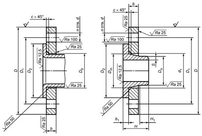
Fig. 1.6. Loose steel flanges (types 03 and 04) installation diagram. Fig. 1.7. Welded steel flange (type 11)
Fig. 1.8. Cast steel flange of valve body
Table 1.3. Dimensions of flat welded steel flanges, type 01 in accordance with GOST 54432-2011
| DN | PN | db | b | c1 | D | D1 | d | n | Nominal diameter of bolts or studs | ||
| Row 1 | Row 2 | Row 1 | Row 2 | ||||||||
| DN 10 | PN 1 | 15 | 10 | 2 | 75 | 50 | 11 | 4 | M10 | ||
| PN 2.5 | 18 | 12 | |||||||||
| PN 6 | 12 | ||||||||||
| PN 10 | 14 | 90 | 60 | 14 | M12 | ||||||
| PN 16 | 14 | ||||||||||
| PN 25 | 16 | ||||||||||
| DN 15 | PN 1 | 19 | — | 10 | — | 2 | 80 | 55 | 11 | 4 | M10 |
| PN 2.5 | 22 | 12 | |||||||||
| PN 6 | 12 | ||||||||||
| PN 10 | 14 | 95 | 65 | 14 | M12 | ||||||
| PN 16 | 14 | ||||||||||
| PN 20 | — | — | 12 | 90 | 60,5 | 16 | M14 | ||||
| PN 25 | 19 | 16 | 14 | 95 | 65 | 14 | M12 | ||||
| DN 20 | PN 1 | 26 | — | 12 | — | 2 | 90 | 65 | 11 | 4 | M10 |
| PN 2.5 | 27,5 | 14 | |||||||||
| PN 6 | 14 | ||||||||||
| PN 10 | 16 | 105 | 75 | 14 | M12 | ||||||
| PN 16 | 16 | ||||||||||
| PN 20 | — | 28 | — | 14 | 100 | 70 | 16 | M14 | |||
| PN 25 | 26 | 27,5 | 18 | 16 | 105 | 75 | 14 | M12 | |||
| DN 25 | PN 1 | 33 | — | 12 | — | 3 | 100 | 75 | 11 | 4 | M10 |
| PN 2.5 | 34,5 | 14 | |||||||||
| PN 6 | 14 | ||||||||||
| PN 10 | 16 | 115 | 85 | 14 | M12 | ||||||
| PN 16 | 18 | ||||||||||
| PN 20 | — | — | 110 | 79,5 | 16 | M14 | |||||
| PN 25 | 33 | 18 | 115 | 85 | 14 | M12 | |||||
| DN 32 | PN 1 | 39 | — | 12 | — | 3 | 120 | 90 | 14 | 4 | M12 |
| PN 2.5 | 43,5 | 16 | |||||||||
| PN 6 | 15 | ||||||||||
| PN 10 | 16 | 18 | 135 | 100 | 18 | M16 | |||||
| PN 16 | 18 | ||||||||||
| PN 20 | — | — | 120 | 89 | 16 | M14 | |||||
| PN 25 | 39 | 20 | 135 | 100 | 18 | M16 | |||||
| DN 40 | PN 1 | 46 | — | 13 | — | 3 | 130 | 100 | 14 | 4 | M12 |
| PN 2.5 | 49,5 | 16 | |||||||||
| PN 6 | 16 | ||||||||||
| PN 10 | 18 | 18 | 145 | 110 | 18 | M16 | |||||
| PN 16 | 20 | ||||||||||
| PN 20 | — | — | 19 | 130 | 98,5 | 16 | M14 | ||||
| PN 25 | 46 | 22 | 18 | 145 | 110 | 18 | M16 | ||||
| DN 50 | PN 1 | 59 | — | 13 | — | 3 | 140 | 110 | 14 | 4 | M12 |
| PN 2.5 | 61,5 | 16 | |||||||||
| PN 6 | 16 | ||||||||||
| PN 10 | 18 | 20 | 160 | 125 | 18 | M16 | |||||
| PN 16 | 22 | ||||||||||
| PN 20 | — | 62 | — | 21 | 150 | 120,5 | |||||
| PN 25 | 59 | 61,5 | 24 | 20 | 160 | 125 | |||||
| DN 65 | PN 1 | 78 | — | 14 | — | 4 | 160 | 130 | 14 | 4 | M12 |
| PN 2.5 | 77,5 | 16 | |||||||||
| PN 6 | 16 | ||||||||||
| PN 10 | 20 | 20 | 180 | 145 | 18 | 8 | M16 | ||||
| PN 16 | 24 | 20 | |||||||||
| PN 20 | — | 74,5 | — | 24 | 139,5 | 4 | |||||
| PN 25 | 78 | 77,5 | 24 | 22 | 145 | 8 | |||||
| DN 80 | PN 1 | 91 | — | 14 | — | 4 | 185 | 150 | 18 | 4 | M16 |
| PN 2.5 | 90,5 | 18 | |||||||||
| PN 6 | 18 | ||||||||||
| PN 10 | 20 | 20 | 195 | 160 | 8 | ||||||
| PN 16 | 24 | ||||||||||
| PN 20 | — | — | 26 | 190 | 152,5 | 4 | |||||
| PN 25 | 91 | 26 | 24 | 195 | 160 | 8 | |||||
| DN 100 | PN 1 | 110 116 | — | 14 | — | 4 | 205 | 170 | 18 | 4 | M16 |
| PN 2.5 | 110 116 | 116 | 18 | ||||||||
| PN 6 | 110 116 | 18 | |||||||||
| PN 10 | 110 116 | 22 | 22 | 215 | 180 | 8 | |||||
| PN 16 | 110 116 | 26 | |||||||||
| PN 20 | — | — | 27 | 230 | 195,5 | ||||||
| PN 25 | 110 116 | 28 | 26 | 190 | 22 | M20 | |||||
| DN 120 | PN 1 | 135 142 | — | 16 | — | 4 | 235 | 200 | 18 | 8 | M16 |
| PN 2.5 | 135 142 | 141,5 | 20 | ||||||||
| PN 6 | 135 142 | 20 | |||||||||
| PN 10 | 135 142 | 24 | 22 | 245 | 210 | ||||||
| PN 16 | 135 142 | 28 | |||||||||
| PN 20 | — | 143,5 | — | 28 | 255 | 216 | 22 | M20 | |||
| PN 25 | 135 142 | 141,5 | 30 | 270 | 220 | 26 | M24 | ||||
| DN 150 | PN 1 | 154 161 170 | — | 16 | — | 4 | 260 | 225 | 18 | 8 | M16 |
| PN 2.5 | 154 161 170 | 170,5 | 16 | 20 | |||||||
| PN 6 | 154 161 170 | 20 | |||||||||
| PN 10 | 154 161 170 | 24 | 24 | 280 | 240 | 22 | M20 | ||||
| PN 16 | 154 161 170 | 28 | |||||||||
| PN 20 | — | — | 31 | 241,5 | |||||||
| PN 25 | 154 161 170 | 30 | 30 | 300 | 250 | 26 | M24 | ||||
| DN 200 | PN 1 | 222 | — | 18 | — | 4 | 315 | 280 | 18 | 8 | M16 |
| PN 2.5 | 221,5 | 22 | |||||||||
| PN 6 | 22 | ||||||||||
| PN 10 | 24 | 24 | 335 | 295 | 22 | M20 | |||||
| PN 16 | 30 | 26 | 12 | ||||||||
| PN 20 | — | — | 34 | 345 | 298,5 | 8 | |||||
| PN 25 | 222 | 32 | 32 | 360 | 310 | 26 | 12 | M24 | |||
| DN 250 | PN 1 | 273 | — | 21 | — | 6 | 370 | 335 | 18 | 12 | M16 |
| PN 2.5 | 276,5 | 24 | |||||||||
| PN 6 | 23 | ||||||||||
| PN 10 | 26 | 26 | 390 | 350 | 22 | M20 | |||||
| PN 16 | 31 | 28 | 405 | 355 | 26 | M24 | |||||
| PN 20 | — | 276 | — | 38 | 362 | ||||||
| PN 25 | 273 | 276,5 | 34 | 35 | 425 | 370 | 30 | M27 | |||
| DN 300 | PN 1 | 325 | — | 22 | — | 6 | 435 | 395 | 22 | 12 | M20 |
| PN 2.5 | 327,5 | 24 | |||||||||
| PN 6 | 24 | ||||||||||
| PN 10 | 28 | 28 | 440 | 400 | |||||||
| PN 16 | 32 | 32 | 460 | 410 | 26 | M24 | |||||
| PN 20 | — | 327 | — | 42 | 485 | 432 | |||||
| PN 25 | 325 | 327,5 | 36 | 38 | 430 | 30 | 16 | M27 | |||
| DN 350 | PN 1 | 377 | — | 22 | — | 7 | 485 | 445 | 22 | 12 | M20 |
| PN 2.5 | 359,5 | 26 | |||||||||
| PN 6 | 26 | ||||||||||
| PN 10 | 28 | 30 | 500 | 460 | 16 | ||||||
| PN 16 | 34 | 35 | 520 | 470 | 26 | M24 | |||||
| PN 20 | — | 359 | — | 43 | 535 | 476 | 29,5 | 12 | M27 | ||
| PN 25 | 377 | 359,5 | 42 | 42 | 550 | 490 | 33 | 16 | M30 | ||
| DN 400 | PN 1 | 426 | — | 22 | — | 7 | 540 | 495 | 22 | 16 | M20 |
| PN 2.5 | 411 | 28 | |||||||||
| PN 6 | 28 | ||||||||||
| PN 10 | 30 | 32 | 565 | 515 | 26 | M24 | |||||
| PN 16 | 38 | 38 | 580 | 525 | 30 | M27 | |||||
| PN 20 | — | 410,5 | — | 48 | 600 | 540 | 29,5 | ||||
| PN 25 | 426 | 411 | 44 | 46 | 610 | 550 | 36 | M33 | |||
| DN 450 | PN 1 | 480 | — | 24 | — | 7 | 590 | 550 | 22 | 16 | M20 |
| PN 2.5 | 462 | 30 | |||||||||
| PN 6 | 28 | ||||||||||
| PN 10 | 30 | 35 | 615 | 565 | 26 | 20 | M24 | ||||
| PN 16 | 42 | 42 | 640 | 585 | 30 | M27 | |||||
| PN 20 | — | — | 52 | 635 | 578 | 32,5 | 16 | M30 | |||
| PN 25 | 480 | 48 | 50 | 660 | 600 | 36 | 20 | M33 | |||
| DN 500 | PN 1 | 530 | — | 24 | — | 7 | 640 | 600 | 22 | 20 | M20 |
| PN 2.5 | 513,5 | 32 | |||||||||
| PN 6 | 29 | ||||||||||
| PN 10 | 32 | 38 | 670 | 620 | 26 | M24 | |||||
| PN 16 | 48 | 46 | 710 | 650 | 33 | M30 | |||||
| PN 20 | — | 513 | — | 56 | 700 | 635 | 32,5 | ||||
| PN 25 | 530 | 513,5 | 52 | 53 | 730 | 660 | 36 | M33 | |||
| DN 600 | PN 1 | 630 | 25 | 7 | 755 | 705 | 26 | 20 | M24 | ||
| PN 2.5 | 616,5 | 36 | |||||||||
| PN 6 | 30 | ||||||||||
| PN 10 | 36 | 42 | 780 | 725 | 30 | M27 | |||||
| PN 16 | 50 | 52 | 840 | 770 | 36 | M33 | |||||
| PN 20 | — | 616 | — | 62 | 815 | 749,5 | 35,5 | ||||
| PN 25 | 630 | 616,5 | 54 | 68 | 840 | 770 | 39 | M36 | |||
| DN 700 | PN 1 | 720 | — | 26 | — | 9 | 860 | 810 | 26 | 24 | M24 |
| PN 2.5 | * | 36 | |||||||||
| PN 6 | 32 | 40 | |||||||||
| PN 10 | — | 39 | — | 895 | 840 | 30 | M27 | ||||
| PN 16 | 52 | 910 | 36 | M33 | |||||||
| PN 25 | 60 | 960 | 875 | 42 | M39 | ||||||
| DN 800 | PN 1 | 820 | — | 26 | — | 9 | 975 | 920 | 30 | 24 | M27 |
| PN 2.5 | * | 38 | 30 | ||||||||
| PN 6 | 32 | 44 | |||||||||
| PN 10 | — | 42 | — | 1010 | 950 | 33 | M30 | ||||
| PN 16 | 54 | 1020 | 39 | M36 | |||||||
| PN 25 | 68 | 1075 | 990 | 48 | M45 | ||||||
| DN 900 | PN 1 | 920 | — | 28 | — | 9 | 1075 | 1020 | 30 | 24 | M27 |
| PN 2.5 | * | 40 | |||||||||
| PN 6 | 34 | 48 | |||||||||
| PN 10 | — | 45 | — | 1110 | 1050 | 33 | 28 | M30 | |||
| PN 16 | 59 | 1120 | 39 | M36 | |||||||
| DN 1000 | PN 1 | 1020 | — | 30 | — | 10 | 1175 | 1120 | 30 | 28 | M27 |
| PN 2.5 | * | 42 | |||||||||
| PN 6 | 36 | 52 | |||||||||
| PN 10 | — | 48 | — | 1220 | 1060 | 36 | M33 | ||||
| PN 16 | 63 | 1255 | 1170 | 42 | M39 | ||||||
| DN 1200 | PN 1 | 1220 | 30 | 10 | 1375 | 1320 | 30 | 32 | M27 | ||
| PN 2.5 | * | 44 | |||||||||
| PN 6 | 39 | 60 | 1400 | 1340 | 33 | M30 | |||||
| PN 10 | 1222 | — | 56 | — | 1455 | 1380 | 39 | M36 | |||
| PN 16 | 1220 | 76 | 1485 | 1390 | 48 | M45 | |||||
| DN 1400 | PN 1 | 1420 | 32 | 10 | 1575 | 1520 | 30 | 36 | M27 | ||
| PN 2.5 | * | 48 | |||||||||
| PN 6 | 48 | 68 | 1620 | 1560 | 36 | M33 | |||||
| PN 10 | — | 65 | — | 1675 | 1590 | 42 | M39 | ||||
* The diameter of the bore is specified by the customer. Notes: 1. Size c1 can be specified depending on the welding technology and pipe size. 2. Flanges must be manufactured with A, B, C, D, E, F, L and M sealing surfaces.
Table 1.4. Dimensions of steel butt-welded flanges, type 11 in accordance with GOST 54432-2011
| DN | PN, kg / cm2 | Dm | D n | H1 | b | H | H1 | D | D1 | d | n | Nominal diameter of bolts or studs | |||||
| Row 1 | Row 2 | Row 1 | Row 2 | Row 1 | Row 2 | Row 1 | Row 2 | Row 1 | Row 2 | ||||||||
| DN 10 | PN 1 | 22 | — | 15 | — | 8 | — | 10 | — | — | 5 | 75 | 50 | 11 | 4 | M10 | |
| PN 2.5 | 26 | 17,2 | 14 | 1 12 | 28 | ||||||||||||
| PN 6 | 12 | 29 | |||||||||||||||
| PN 10 | 25 | 28 | 12,6 | 14 | 35 | 35 | 90 | 60 | 14 | M12 | |||||||
| PN 16 | 26 | 14 | |||||||||||||||
| PN 25 | 16 | ||||||||||||||||
| DN 15 | PN 1 | 28 | — | 19 | — | 12 | — | 10 | — | 28 | — | 6 | 80 | 55 | 11 | M10 | |
| PN 2.5 | 30 | 21,3 | 17,7 | 12 | 30 | ||||||||||||
| PN 6 | 12 | 30 | |||||||||||||||
| PN 10 | 30 | 32 | 14,9 | 14 | 35 | 38 | 95 | 65 | 14 | M12 | |||||||
| PN 16 | 14 | ||||||||||||||||
| PN 20 | — | 30 | — | 21,5 | — | 16 | — | 11,5 | — | 48 | 90 | 60,5 | 16 | M14 | |||
| PN 25 | 30 | 32 | 19 | 21,3 | 12 | 14,9 | 16 | 14 | 35 | 38 | 95 | 65 | 14 | M12 | |||
| PN 40 | |||||||||||||||||
| DN 20 | PN 1 | 36 | — | 26 | — | 18 | — | 10 | — | 30 | — | 90 | 65 | 11 | M10 | ||
| PN 2.5 | 38 | 26,9 | 23,5 | 14 | 32 | ||||||||||||
| PN 6 | 12 | 32 | |||||||||||||||
| PN 10 | 38 | 40 | 20,5 | 14 | 16 | 38 | 40 | 105 | 75 | 14 | M12 | ||||||
| PN 16 | |||||||||||||||||
| PN 20 | — | 38 | — | 26,5 | — | 21 | — | 13 | — | 52 | 100 | 70 | 16 | M14 | |||
| PN 25 | 38 | 40 | 26 | 26,9 | 18 | 20,5 | 16 | 36 | 40 | 105 | 75 | 14 | M12 | ||||
| PN 40 | 16 | ||||||||||||||||
| DN 25 | PN 1 | 42 | — | 33 | — | 25 | — | 10 | — | 30 | — | 100 | 75 | 11 | M10 | ||
| PN 2.5 | 42 | 33,7 | 29,7 | 14 | 35 | ||||||||||||
| PN 6 | 14 | 32 | |||||||||||||||
| PN 10 | 45 | 46 | 27,3 | 16 | 40 | 40 | 115 | 85 | 14 | M12 | |||||||
| PN 16 | |||||||||||||||||
| PN 20 | — | 49 | — | 33,5 | — | 26,5 | — | 14,5 | — | 56 | 110 | 79,5 | 16 | M14 | |||
| PN 25 | 45 | 46 | 33 | 33,7 | 25 | 27,3 | 16 | 16 | 38 | 40 | 115 | 85 | 14 | M12 | |||
| DN 32 | PN 1 | 50 | — | 39 | — | 31 | — | 10 | — | 30 | — | 7 | 120 | 90 | 14 | M12 | |
| PN 2.5 | 55 | 42,4 | 37,8 | 16 | 35 | ||||||||||||
| PN 6 | 14 | 35 | |||||||||||||||
| PN 10 | 55 | 56 | 35,2 | 15 | 18 | 42 | 42 | 135 | 100 | 18 | М16 | ||||||
| PN 16 | |||||||||||||||||
| PN 20 | — | 59 | — | 42 | — | 35 | — | 16 | — | 57 | 120 | 89 | 16 | M14 | |||
| PN 25 | 56 | 56 | 39 | 42,4 | 31 | 35,2 | 18 | 18 | 45 | 42 | 100 | ||||||
| DN 40 | PN 1 | 60 | — | 46 | — | 38 | — | 12 | — | 36 | — | 7 | 130 | 100 | 14 | M12 | |
| PN 2.5 | 62 | 48,3 | 43,7 | 16 | 38 | ||||||||||||
| PN 6 | 15 | 38 | |||||||||||||||
| PN 10 | 62 | 64 | 41,1 | 16 | 18 | 45 | 45 | 145 | 110 | 18 | М16 | ||||||
| PN 16 | 64 | ||||||||||||||||
| PN 20 | — | 65 | — | 48,5 | — | 41 | — | 17,5 | — | 62 | 130 | 98,5 | 16 | M14 | |||
| PN 25 | 64 | 64 | 46 | 48,3 | 38 | 41,1 | 19 | 18 | 48 | 45 | 145 | 110 | 18 | М16 | |||
| DN 50 | PN 1 | — | 58 | — | 49 | — | 12 | — | 36 | — | 8 | 140 | 110 | 14 | 4 | M12 | |
| PN 2.5 | 70 | 55,7 | 16 | 38 | |||||||||||||
| PN 6 | 74 | 60,3 | 15 | 38 | |||||||||||||
| PN 10 | 76 | 52,3 | 16 | 20 | 45 | 48 | 160 | 125 | 18 | М16 | |||||||
| PN 16 | 48 | ||||||||||||||||
| PN 20 | — | 78 | — | 60,5 | — | 52,5 | — | 19,5 | — | 64 | 150 | 120,5 | |||||
| PN 25 | 76 | 74 | 58 | 60,3 | 49 | 52,3 | 20 | 20 | 48 | 48 | 160 | 125 | |||||
| DN 65 | PN 1 | 88 | 77 | — | 66 | 12 | — | 36 | — | 9 | 160 | 130 | 14 | 4 | M12 | ||
| PN 2.5 | 88 | 76,1 | 70,9 | 16 | 38 | ||||||||||||
| PN 6 | 15 | 38 | |||||||||||||||
| PN 10 | 94 | 92 | 70,3 | 18 | 20 | 48 | 45 | 10 | 180 | 145 | 18 | 8 | М16 | ||||
| PN 16 | 50 | ||||||||||||||||
| PN 20 | — | 90 | — | 73 | — | 62,5 | — | 22,5 | — | 70 | 139,5 | 4 | |||||
| PN 25 | 96 | 92 | 77 | 76,1 | 66 | 66,1 | 22 | 22 | 53 | 52 | 145 | ||||||
| DN 80 | PN 1 | 102 | — | 90 | — | 78 | — | 14 | — | 38 | — | 10 | 185 | 150 | 18 | 4 | М16 |
| PN 2.5 | 102 | 88,9 | 83,1 | 18 | 42 | ||||||||||||
| PN 6 | 16 | 40 | 8 | ||||||||||||||
| PN 10 | 105 | 110 | 82,5 | 18 | 20 | 50 | 50 | 195 | 160 | ||||||||
| PN 16 | 110 | 20 | 53 | 4 | |||||||||||||
| PN 20 | — | 108 | — | 89 | — | 78 | — | — | 70 | 190 | 152,5 | ||||||
| PN 25 | 110 | 110 | 90 | 88,9 | 78 | 77,7 | 22 | 24 | 55 | 58 | 195 | 160 | |||||
| DN 100 | PN 1 | 122 | — | 110 | — | 96 | — | 14 | — | 40 | — | 10 | 205 | 170 | 18 | 4 | М16 |
| PN 2.5 | 130 | 114,3 | 107,9 | 18 | 45 | ||||||||||||
| PN 6 | 16 | 41 | |||||||||||||||
| PN 10 | 128 | 107,1 | 20 | 22 | 51 | 52 | 215 | 180 | 8 | ||||||||
| PN 16 | 130 | 53 | |||||||||||||||
| PN 20 | — | 135 | — | 114,5 | — | 102,5 | — | — | 76 | 190,5 | |||||||
| PN 25 | 132 | 134 | 110 | 114,3 | 96 | 101,7 | 24 | 24 | 61 | 65 | 230 | 190 | |||||
| DN 125 | PN 1 | 148 | — | 135 | — | 121 | — | 14 | — | 40 | — | 10 | 235 | 200 | 18 | 8 | М16 |
| PN 2.5 | 155 | 139,7 | 132,5 | 18 | 48 | ||||||||||||
| PN 6 | 18 | 43 | |||||||||||||||
| PN 10 | 156 | 158 | 131,7 | 22 | 22 | 60 | 55 | 245 | 210 | ||||||||
| PN 16 | |||||||||||||||||
| PN 20 | — | 164 | — | 141,5 | — | 128 | — | 24 | — | 89 | 12 | 255 | 216 | 22 | M20 | ||
| DN 150 | PN 1 | 172 | — | 161 | — | 146 | — | 14 | — | 41 | — | 10 | 260 | 225 | 18 | 8 | М16 |
| PN 2.5 | 184 | 168,3 | 160,3 | 20 | 48 | ||||||||||||
| PN 6 | 18 | 46 | |||||||||||||||
| PN 10 | 180 | 159,3 | 22 | 24 | 60 | 55 | 280 | 240 | 22 | M20 | |||||||
| PN 16 | |||||||||||||||||
| PN 20 | — | 192 | — | 168,5 | — | 154 | — | 25,5 | — | 89 | 12 | 241,5 | 22 | ||||
| DN 200 | PN 1 | 235 | — | 222 | — | 202 | — | 16 | — | 48 | — | 16 | 315 | 280 | 18 | 8 | М16 |
| PN 2.5 | 236 | 219,1 | 210,1 | 22 | 55 | ||||||||||||
| PN 6 | 20 | 53 | |||||||||||||||
| PN 10 | 240 | 234 | 206,5 | 22 | 24 | 61 | 62 | 335 | 295 | 22 | M20 | ||||||
| PN 16 | 24 | 12 | |||||||||||||||
| PN 20 | — | 246 | — | 219 | — | 202,5 | — | 29 | — | 102 | 345 | 298,5 | 8 | ||||
| PN 25 | 245 | 244 | 222 | 219,1 | 202 | 206,5 | 30 | 30 | 78 | 80 | 360 | 310 | 26 | 12 | M24 | ||
| DN 250 | PN 1 | 288 | — | 278 | — | 254 | — | 19 | — | 48 | — | 16 | 370 | 335 | 18 | М16 | |
| PN 2.5 | 290 | 273 | 263 | 24 | 60 | ||||||||||||
| PN 6 | 288 | 290 | 21 | 53 | |||||||||||||
| PN 10 | 290 | 288 | 260,4 | 24 | 26 | 63 | 68 | 390 | 350 | 22 | M20 | ||||||
| PN 16 | 292 | 26 | 26 | 68 | 70 | 20 | 405 | 355 | 26 | M24 | |||||||
| PN 20 | 305 | — | — | 254,5 | — | 30,5 | — | 102 | 362 | 26 | |||||||
| PN 25 | 300 | 296 | 278 | 254 | 260,4 | 32 | 32 | 78 | 88 | 425 | 370 | 30 | M27 | ||||
| DN 300 | PN 1 | 340 | — | 330 | — | 303 | — | 20 | — | 49 | — | 18 | 435 | 395 | 22 | 12 | M20 |
| PN 2.5 | 342 | 323,9 | 312,7 | 24 | 62 | ||||||||||||
| PN 6 | 22 | 54 | |||||||||||||||
| PN 10 | 345 | 309,7 | 26 | 26 | 64 | 68 | 440 | 400 | |||||||||
| PN 16 | 346 | 28 | 28 | 70 | 78 | 20 | 460 | 410 | 26 | M24 | |||||||
| PN 20 | — | 365 | — | 324 | — | 305 | — | 32 | — | 114 | 485 | 432 | |||||
| PN 25 | 352 | 350 | 330 | 323,9 | 303 | 309,7 | 36 | 34 | 84 | 92 | 430 | 30 | 16 | M27 | |||
| DN 350 | PN 1 | 390 | — | 382 | — | 351 | — | 20 | — | 49 | — | 20 | 485 | 445 | 22 | 12 | M20 |
| PN 2.5 | 385 | 355,6 | 344,4 | 24 | 62 | ||||||||||||
| PN 6 | 22 | 54 | |||||||||||||||
| PN 10 | 400 | 390 | 339,6 | 26 | 26 | 64 | 68 | 500 | 460 | 16 | |||||||
| PN 16 | 32 | 30 | 74 | 82 | 520 | 470 | 26 | M24 | |||||||||
| PN 20 | — | 400 | — | 355,5 | — | * | — | 35 | — | 127 | 22 | 535 | 476 | 29,5 | 12 | M27 | |
| PN 25 | 406 | 398 | 382 | 355,6 | 351 | 339,6 | 40 | 38 | 89 | 100 | 550 | 490 | 33 | 16 | M30 | ||
| DN 400 | PN 1 | 440 | — | 432 | — | 398 | — | 20 | — | 49 | — | 20 | 540 | 495 | 22 | 16 | M20 |
| PN 2.5 | 438 | 406,4 | 393,8 | 24 | 65 | ||||||||||||
| PN 6 | 22 | 54 | |||||||||||||||
| PN 10 | 445 | 440 | 388,8 | 26 | 26 | 64 | 72 | 565 | 515 | 26 | M24 | ||||||
| PN 16 | 450 | 444 | 36 | 32 | 79 | 85 | 580 | 525 | 30 | M27 | |||||||
| PN 20 | — | 457 | — | 406,5 | — | * | — | 37 | — | 127 | 600 | 540 | |||||
| PN 25 | 464 | 452 | 432 | 406,4 | 398 | 388,8 | 44 | 40 | 104 | 110 | 610 | 550 | 36 | M33 | |||
| DN 450 | PN 1 | 494 | — | 484 | — | 450 | — | 20 | — | 54 | — | 22 | 590 | 550 | 22 | 16 | M20 |
| PN 2.5 | 492 | 457 | 444,4 | 24 | 65 | ||||||||||||
| PN 6 | 22 | ||||||||||||||||
| PN 10 | 500 | 488 | 437 | 26 | 28 | 69 | 72 | 615 | 565 | 26 | 20 | M24 | |||||
| PN 16 | 506 | 490 | 38 | 40 | 89 | 87 | 640 | 585 | 30 | M27 | |||||||
| PN 20 | — | 505 | — | — | * | — | — | 140 | 635 | 578 | 32,5 | 16 | M30 | ||||
| PN 25 | 515 | 500 | 484 | 450 | 437 | 46 | 46 | 104 | 110 | 660 | 600 | 36 | 20 | M33 | |||
| DN 500 | PN 1 | 545 | — | 535 | — | 501 | — | 23 | — | 54 | — | 20 | 640 | 600 | 22 | 20 | M20 |
| PN 2.5 | 538 | 508 | 495,4 | 26 | 68 | ||||||||||||
| PN 6 | 54 | ||||||||||||||||
| PN 10 | 550 | 540 | 486 | 28 | 28 | 69 | 75 | 22 | 670 | 620 | 26 | M24 | |||||
| PN 16 | 559 | 546 | 42 | 44 | 94 | 90 | 710 | 650 | 33 | M30 | |||||||
| PN 20 | — | 559 | — | — | * | — | 43 | — | 145 | 700 | 635 | 32,5 | |||||
| PN 25 | 570 | 558 | 535 | 500 | 486 | 48 | 48 | 104 | 125 | 730 | 660 | 36 | M33 | ||||
| DN 600 | PN 1 | 650 | — | 636 | — | 602 | — | 24 | — | 60 | — | 18 | 755 | 705 | 26 | 20 | M24 |
| PN 2.5 | 640 | 610 | 597,4 | 30 | 70 | ||||||||||||
| PN 6 | |||||||||||||||||
| PN 10 | 585 | 29 | 34 | 70 | 80 | 780 | 725 | 30 | M27 | ||||||||
| PN 16 | 660 | 650 | 46 | 54 | 95 | 95 | 840 | 770 | 36 | M33 | |||||||
| PN 20 | — | 664 | — | 609,5 | — | * | — | 48 | — | 152 | 815 | 749,5 | 35,5 | ||||
| PN 25 | 670 | 660 | 636 | 610 | 600 | 585 | 54 | 58 | 120 | 125 | 20 | 840 | 770 | 39 | M36 | ||
| DN 700 | PN 1 | 740 | — | 726 | — | 692 | * | 24 | — | — | 20 | 860 | 810 | 26 | 24 | M24 | |
| PN 2.5 | 740 | 711 | 26 | 60 | 70 | ||||||||||||
| PN 6 | |||||||||||||||||
| PN 10 | 744 | 746 | 30 | 30 | 70 | 80 | 895 | 840 | 30 | M27 | |||||||
| PN 16 | 750 | 750 | 48 | 38 | 100 | 100 | 910 | 36 | M33 | ||||||||
| PN 25 | 766 | 760 | 726 | 690 | 58 | 46 | 130 | 125 | 960 | 875 | 42 | M39 | |||||
| DN 800 | PN 1 | — | 826 | — | 792 | * | 24 | — | — | 20 | 975 | 920 | 30 | 24 | M27 | ||
| PN 2.5 | 844 | 842 | 813 | 26 | 65 | 70 | |||||||||||
| PN 6 | |||||||||||||||||
| PN 10 | 850 | 848 | 32 | 32 | 80 | 90 | 1010 | 950 | 33 | M30 | |||||||
| PN 16 | 50 | 38 | 100 | 105 | 1020 | 39 | M36 | ||||||||||
| PN 25 | 874 | 864 | 826 | 813 | 790 | 60 | 50 | 140 | 135 | 1075 | 990 | 48 | M45 | ||||
| DN 900 | PN 1 | — | 926 | — | 892 | * | 26 | — | 65 | — | 20 | 1075 | 1020 | 30 | 24 | ||
| PN 2.5 | 944 | 942 | 914 | 26 | 70 | M27 | |||||||||||
| PN 6 | |||||||||||||||||
| PN 10 | 950 | 948 | 34 | 34 | 85 | 95 | 1115 | 1050 | 33 | 28 | M30 | ||||||
| PN 16 | 958 | 52 | 40 | 115 | 110 | 1120 | 39 | M36 | |||||||||
| PN 25 | 980 | 968 | 926 | 914 | 892 | 62 | 54 | 150 | 145 | 1185 | 1090 | 48 | M45 | ||||
| DN 1000 | PN 1 | 1044 | — | 1028 | — | 992 | * | 26 | — | 65 | — | 16 | 1175 | 1120 | 30 | 28 | M27 |
| PN 2.5 | 1045 | 1016 | 26 | 70 | |||||||||||||
| PN 6 | |||||||||||||||||
| PN 10 | 1050 | 1050 | 34 | 34 | 85 | 95 | 22 | 1230 | 1160 | 36 | M33 | ||||||
| PN 16 | 1060 | 1056 | 54 | 42 | 115 | 120 | 1255 | 1170 | 42 | M39 | |||||||
| PN 25 | 1084 | 1070 | 1028 | 1016 | 992 | 64 | 58 | 155 | 155 | 1315 | 1210 | 55 | M52 | ||||
| DN 1200 | PN 1 | 1244 | — | 1228 | — | 1192 | — | 28 | — | 70 | — | 16 | 1375 | 1320 | 30 | 32 | M27 |
| PN 2.5 | 1245 | 1220 | * | 26 | 70 | ||||||||||||
| PN 6 | 1248 | 1248 | 28 | 75 | 90 | 20 | 1400 | 1340 | 33 | M30 | |||||||
| PN 10 | 1256 | 1256 | 38 | 38 | 95 | 115 | 25 | 1455 | 1380 | 39 | M36 | ||||||
| PN 16 | 1268 | 1260 | 56 | 48 | 130 | 130 | 1485 | 1390 | 48 | M45 | |||||||
| PN 25 | 1288 | 1228 | 1192 | 67 | — | 165 | 30 | 1525 | 1420 | 55 | M52 | ||||||
| DN 1400 | PN 1 | 1445 | — | 1428 | — | 1392 | — | 28 | — | 70 | — | 16 | 1575 | 1520 | 30 | 36 | M27 |
| PN 2.5 | 1445 | 1420 | * | 26 | 70 | ||||||||||||
| PN 6 | 1456 | 1452 | 32 | 32 | 90 | 90 | 20 | 1620 | 1560 | 36 | M33 | ||||||
| PN 10 | 1460 | — | — | — | 42 | — | 120 | 25 | 1675 | 1590 | 42 | M39 | |||||
| PN 16 | 1465 | 52 | 145 | 30 | 1685 | 48 | M45 | ||||||||||
| DN 2200 | PN 2.5 | — | 2248 | — | — | * | — | 28 | — | 90 | 25 | 2405 | 2340 | 33 | 52 | M30 | |
| PN 6 | 2260 | 2220 | 42 | 115 | 2475 | 2390 | 42 | M39 | |||||||||
| PN 10 | 2275 | 58 | 160 | 35 | 2550 | 2440 | 55 | M52 | |||||||||
| DN 2400 | PN 2.5 | — | 2448 | — | 2420 | — | * | — | 28 | — | 90 | 25 | 2605 | 2540 | 33 | 56 | M30 |
| PN 6 | 2462 | 44 | 125 | 2685 | 2600 | 42 | M39 | ||||||||||
| PN 10 | 2478 | 62 | 170 | 35 | 2760 | 2650 | 55 | M52 | |||||||||
| DN 2600 | PN 2.5 | — | 2648 | — | 2620 | — | * | — | 28 | — | 90 | 25 | 2805 | 2740 | 33 | 60 | M30 |
| PN 6 | 2665 | 46 | 130 | 2905 | 2810 | 48 | M45 | ||||||||||
| PN 10 | 2680 | 66 | 180 | 40 | 2960 | 2850 | 55 | M52 | |||||||||
| DN 2800 | PN 2.5 | — | 2848 | — | 2820 | — | * | — | 30 | — | 90 | 25 | 3030 | 2960 | 36 | 64 | M33 |
| PN 6 | 2865 | 48 | 135 | 30 | 3115 | 3020 | 48 | M45 | |||||||||
| PN 10 | 2882 | 70 | 190 | 40 | 3180 | 3070 | 55 | M52 | |||||||||
| DN 3000 | PN 2.5 | — | 3050 | — | 3020 | — | * | — | 30 | — | 90 | 25 | 3230 | 3160 | 36 | 68 | M33 |
| PN 6 | 3068 | 50 | 140 | 30 | 3315 | 3220 | 48 | M45 | |||||||||
| PN 10 | 3085 | 75 | 200 | 45 | 3405 | 3290 | 60 | M56 | |||||||||
| DN 3200 | PN 2.5 | — | 3250 | — | 3220 | — | * | — | 30 | — | 90 | 25 | 3430 | 3360 | 36 | 72 | M33 |
| PN 6 | 3272 | 54 | 150 | 30 | 3525 | 3430 | 48 | M45 | |||||||||
| DN 3400 | PN 2.5 | — | 3450 | — | 3420 | — | * | — | 32 | — | 95 | 28 | 3630 | 3560 | 36 | 76 | M33 |
| PN 6 | 3475 | 56 | 160 | 35 | 3735 | 3640 | 48 | M45 | |||||||||
| DN 3600 | PN 2.5 | — | 3652 | — | 3620 | — | * | — | 32 | — | 100 | 28 | 3840 | 3770 | 36 | 80 | M33 |
| PN 6 | 3678 | 60 | 165 | 35 | 3970 | 3860 | 55 | M52 | |||||||||
| DN 3800 | PN 2.5 | — | 3852 | — | 3820 | — | * | — | 34 | — | 100 | 28 | 4045 | 3970 | 39 | 80 | M36 |
| DN 4000 | PN 2.5 | — | 4052 | — | 4020 | — | * | — | 34 | — | 100 | 28 | 4245 | 4170 | 39 | 84 | M36 |
* The size is set by the customer.
Note. Flanges must be manufactured with sealing surfaces of the following versions:
- - А, В - for flanges with РN ≤ 63;
- - C, D, E, F, J, K, L, M - for all PN.
It is allowed to produce flanges of all designs (except for flanges for row 2), which have four holes for studs (bolts), square for a nominal pressure of no more than PN 40. The dimensions of square flanges are shown in Fig. 1.9 and in tab. 1.5. The list of materials used for the manufacture of flanges is given in tab. 1.6, the estimated weight of the flanges is in tab. 1.7.
All flanges other than type 21 shall be marked as follows:
- manufacturer's trademark;
- DN;
- PN;
- flange type number;
- size range number (1 or 2);
- the design of the sealing surface according to fig. 1.2;
- flange material grade;
- control group.
Example of marking for a steel butt-weld flange DN 50 to PN 10, type 11, row 1, version M, made of steel 25 according to control group IV:
Manufacturer's trademark - 50-10-11-1-M-St 25-IV.
For flanges with control group V, the serial number is additionally marked.
In tab. 1.8 and in tab. 1.9 shows comparative designations of flanges and versions of sealing surfaces according to GOST 12817-80 - GOST 12822-80 and according to the national standard GOST R 54432-2011.
Considering the constant increase in the use of foreign-made equipment in Russia, the dimensional drawings of flanges according to the ASME / ANSI standard are shown in Fig. 1.10, and the dimensions and weight of the flanges are in tab. 1.10.
Fig. 1.9. Dimensions of square flanges, D and D1 - in accordance with GOST 54432-2011
Table 1.5. Size B of square flanges, mm
| DN | PN 1 and PN 2.5 | PN 6 | PN 10 | PN 16 | PN 25 | PN 40 |
| DN 10 | 60 | 60 | 70 | 70 | 70 | 70 |
| DN 15 | 65 | 65 | 75 | 75 | 75 | 75 |
| DN 20 | 70 | 70 | 80 | 80 | 80 | 80 |
| DN 25 | 75 | 75 | 90 | 90 | 90 | 90 |
| DN 32 | 95 | 95 | 105 | 105 | 105 | 105 |
| DN 40 | 100 | 100 | 110 | 110 | 110 | 110 |
| DN 50 | 110 | 110 | 125 | 125 | 125 | 125 |
| DN 65 | 125 | 125 | 140 | 140 | — | — |
| DN 80 | 140 | 140 | — | — | — | — |
| DN 100 | 155 | 155 | — | — | — | — |
Table 1.6. Recommended flange materials
| Steel or cast iron group | Material grade | Application temperature, ° С | PN, MPa (kgf / cm2), no more |
| Unalloyed steel casting | 25L-II 20L-III 25L-III | -30 to 450 | 6,3 (63) 20 (200) |
| Alloy steel casting | 20H5ML 20GML | -60 to 650 -40 to 450 | |
| High alloy steel casting | 16Х18Н12С4ТUL 12Х18Н9ТЛ 10Х18Н9Л | -70 to 300 | |
| Carbon steel | St3sp not lower than the 2nd category 20 20K 20KA | –253 to 600 –30 to 300 –20 to 300 –40 to 475 –20 to 475 –30 to 475 –40 to 475 | 10 (100) 20 (200) |
| Low alloy steel | 20YUCH 15GS 16GS 10G2S1 17GS 12HM 15HM 09G2S 10G2 | –40 to 475 –30 to 475 –70 to 475 –40 to 475 –30 to 475 –40 to 475 –40 to 560 –70 to 475 | |
| Heat-resistant steel | 15Х5М | -40 to 650 | |
| Corrosion-resistant steel | 08Х18Н10Т 12Х18Н9Т 12Х18Н10Т 10Х18Н9 08Х22Н6Т 08Х21Н6М2Т 15Х18Н12С4ТЮ 06ХН28МДТ 10Х17Н13М3Т 10Х17Н13М2Т 07Х20Н25М3Д2ТЛ ЭИ 943Л | –270 to 610 –270 to 600 –40 to 300 –70 to 300 –196 to 400 –196 to 600 –253 to 700 –70 to 300 |
Table 1.7. Estimated weight of flanges
| DN | Flange type | Flange weight, kg, for PN, kgf / cm2 | ||||
| PN 1 and PN 2.5 | PN 6 | PN 10 | PN 16 | PN 25 | ||
| DN 25 | 01 02 11 | 0,55 0,60 0,55 | 0,64 0,60 0,76 | 0,89 0,96 1,05 | 1,17 1,10 1,05 | 1,17 1,24 1,19 |
| DN 32 | 01 02 11 | 0,79 0,87 0,78 | 1,01 0,87 1,10 | 1,40 1,49 1,54 | 1,58 1,68 1,54 | 1,77 1,87 1,85 |
| DN 40 | 01 02 11 | 0,95 1,01 1,09 | 1,21 1,01 1,36 | 1,71 1,92 1,83 | 1,96 2,13 1,85 | 2,18 2,35 2,19 |
| DN 50 | 01 02 11 | 1,04 1,11 1,26 | 1,33 1,11 1,53 | 2,06 2,27 2,26 | 2,58 2,54 2,28 | 2,71 2,79 2,78 |
| DN 65 | 01 02 11 | 1,39 1,55 1,62 | 1,63 1,55 1,97 | 2,80 3,01 3,17 | 3,42 3,31 3,19 | 3,22 3,43 3,71 |
| DN 80 | 01 02 11 | 1,84 2,05 2,43 | 2,44 2,05 2,76 | 3,19 3,77 3,67 | 3,71 4,11 4,21 | 4,06 4,25 4,44 |
| DN 100 | 01 02 11 | 2,14 2,38 2,98 | 2,85 2,38 3,35 | 3,96 4,55 4,70 | 4,73 4,93 4,90 | 5,92 6,19 6,58 |
| DN 125 | 01 02 11 | 2,6 2,84 3,72 | 3,88 2,84 4,66 | 5,40 6,09 6,71 | 6,38 6,56 6,76 | 8,26 8,82 9,45 |
| DN 150 | 01 02 11 | 3,61 3,94 4,30 | 4,63 3,94 5,37 | 6,92 7,86 8,17 | 8,16 8,48 8,30 | 10,5 10,9 12,6 |
| DN 200 | 01 02 11 | 4,73 4,93 6,92 | 5,89 4,93 8,37 | 8,05 9,02 11,4 | 10,1 9,36 11,8 | 13,3 12,6 17,4 |
| DN 250 | 01 02 11 | 6,95 6,38 9,88 | 7,67 6,38 11,0 | 10,7 11,3 14,6 | 14,5 13,9 17,4 | 18,9 17,7 25,7 |
| DN 300 | 01 02 11 | 9,33 10,4 13,4 | 10,3 10,4 14,8 | 12,9 13,9 18,7 | 17,8 17,9 22,8 | 24,0 22,8 33,3 |
| DN 350 | 01 02 11 | 10,5 13,5 16,0 | 12,6 13,5 17,7 | 15,9 18,0 24,0 | 22,9 22,8 32,0 | 34,4 31,7 46,6 |
| DN 400 | 01 02 11 | 11,6 17,0 18,6 | 15,2 17,0 20,6 | 21,6 24,4 30,0 | 31,0 29,1 43,0 | 44,6 42,5 64,8 |
| DN 450 | 01 02 11 | 14,6 20,0 23,6 | 17,3 20,0 23,6 | 22,8 25,6 33,3 | 39,6 35,3 54,0 | 51,8 48,2 72,3 |
| DN 500 | 01 02 11 | 16,0 25,4 26,8 | 19,7 25,4 26,6 | 27,7 33,2 39,2 | 57,0 49,3 71,0 | 67,3 64,6 88,9 |
| DN 600 | 01 11 | 21,4 35,8 | 26,2 35,8 | 39,4 48,8 | 80,0 99,3 | 90,9 124 |
| DN 700 | 01 11 | 29,2 44,3 | 36,7 44,3 | 59,5 65,3 | 84,2 106 | 127 167 |
| DN 800 | 01 11 | 36,6 46,2 | 46,1 56,2 | 79,2 87,2 | 104 131 | 181 215 |
| DN 900 | 01 11 | 44,2 66,4 | 55,1 66,8 | 94,1 103 | 129 158 | — 253 |
| DN 1000 | 01 11 | 52,6 73,4 | 64,4 73,5 | 118 119 | 179 203 | — 312 |
| DN 1200 | 01 11 | 62,4 92,9 | 99,0 111 | 197 180 | 298 285 | — 388 |
| DN 1400 | 01 11 | 77,6 101 | 161 157 | 279 — | — — | — — |
Table 1.8. Flange designation structure
| Picture | GOST 12820-80 - GOST 12822-80 | GOST R 54432-2011 |
| Steel flat welded flanges |
| |
| Butt weld steel flanges | ||
| Loose steel flanges on the welded ring |
|
|
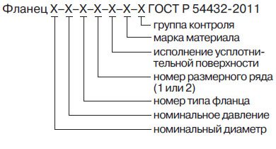

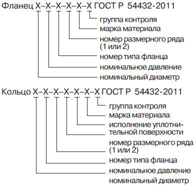
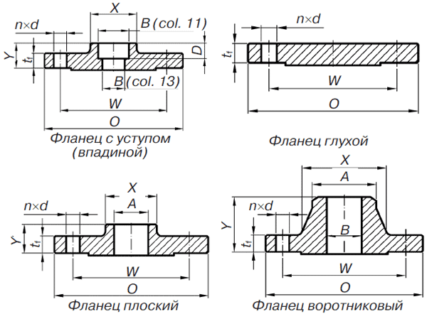
Fig. 1.10. Dimensional Drawings of ASME / ANSI Flanges
Table 1.9. Designation structure of sealing surfaces
| Picture | GOST 12815-80 | GOST R 54432-2011 |
| Plane | — | Execution A |
| Raised flange | Execution 1 | Execution B |
| Raised flange | Execution 2 | Execution E |
| Hollow flange | Execution 3 | Version F |
| Thorn flange | Execution 4, 8 | Execution C, L |
| Flange with groove | Execution 5, 9 | Execution D, M |
| Flange for lens gasket | Version 6 | Version K |
| Oval gasket flange | Version 7 | Execution J |
Table 1.10. ASME / ANSI flange dimensions and weights, for dimensional drawings see fig. 1.10
| DN | Class *** (pressure in psi) | Outside diameter, mm | Divider diameter, circle of studs, mm | Flange thickness, mm | Lower diameter of the neck, mm | Neck diameter, mm | Flange height, mm | Hole diameter, mm | Hollow height | Stud hole diameter, mm | Number of studs | Weight, kg | ||||
| Threaded with socket | Flat | Butt weld | With a hollow | Flat | Butt weld with socket | |||||||||||
| O | W | min. tf | X | BUT | Y | Y | Y | min. AT | min. AT | AT | D | d | n | |||
| 15 (½) | 150 300 600 900/1500 | 90 95 95 120 | 60,3 66,7 66,7 82,6 | 9,6 12,7 14,3 22,3 | 30 38 38 38 | 21,3 21,3 21,3 21,3 | 14 21 22 32 | 46 51 52 60 | 46 51 52 60 | 22,2 22,2 22,2 22,2 | 22,9 22,9 22,9 22,9 | 15,8 15,8 * * | 10 10 10 10 | 15,9 15,9 15,9 22,2 | 4 4 4 4 | 0,8 1,0 1,4 2,2 |
| 20 (¾) | 150 300 600 900/1500 | 100 115 115 130 | 69,9 82,6 82,6 88,9 | 11,2 14,3 15,9 25,4 | 38 48 48 44 | 26,7 26,7 26,7 26,7 | 14 24 25 35 | 51 56 57 70 | 51 56 57 70 | 27,7 27,7 27,7 27,7 | 28,2 28,2 28,2 28,2 | 20,9 20,9 * * | 11 11 11 11 | 15,9 19,0 19,0 22,2 | 4 4 4 4 | 1,0 1,4 1,8 3,2 |
| 25 (1) | 150 300 600 900/1500 | 110 125 125 150 | 79,4 88,9 88,9 101,6 | 12,7 15,9 17,5 28,6 | 49 54 54 52 | 33,4 33,4 33,4 33,4 | 16 25 27 41 | 54 60 62 73 | 54 60 62 73 | 34,5 34,5 34,5 34,5 | 34,9 34,9 34,9 34,9 | 26,6 26,6 * * | 13 13 13 13 | 15,9 19,0 19,0 25,4 | 4 4 4 4 | 1.1 1,8 2,3 4,1 |
| 32 (1¼) | 150 300 600 900/1500 | 115 135 135 160 | 88,9 98,4 98,4 111,1 | 14,3 17,5 20,7 28,6 | 59 64 64 64 | 42,2 42,2 42,2 42,2 | 19 25 29 41 | 56 64 67 73 | 56 64 67 73 | 43,2 43,2 43,2 43,2 | 43,7 43,7 43,7 43,7 | 35,1 35,1 * * | 14 14 14 14 | 15,9 19,0 19,0 25,4 | 4 4 4 4 | 1,4 2,7 3,2 4,5 |
| 40 (1½) | 150 300 600 900/1500 | 125 155 155 180 | 98,4 114,3 114,3 123,8 | 15,9 19,1 22,3 31,8 | 65 70 70 70 | 48,3 48,3 48,3 48,3 | 21 29 32 44 | 60 67 70 83 | 60 67 70 83 | 49,5 49,5 49,5 49,5 | 50,0 50,0 50,0 50,0 | 40,9 40,9 * * | 16 16 16 16 | 15,9 22,2 22,2 28,6 | 4 4 4 4 | 1,8 3,6 4,5 6,4 |
| 50 (2) | 150 300 600 900/1500 | 150 165 165 215 | 120,7 127,0 127,0 165,1 | 17,5 20,7 25,4 38,1 | 78 84 84 105 | 60,3 60,3 60,3 60,3 | 24 32 37 57 | 25 33 37 57 | 62 68 73 102 | 61,9 61,9 61,9 61,9 | 62,5 62,5 62,5 62,5 | 52,5 52,5 * * | 17 17 17 17 | 19,0 19,0 19,0 25,4 | 4 8 8 8 | 2,7 4,1 5,4 11,3 |
| 65 (2½) | 150 300 600 900/1500 | 180 190 190 245 | 139,7 149,2 149,2 190,5 | 20,7 23,9 28,6 41,3 | 90 100 100 124 | 73,0 73,0 73,0 73,0 | 27 37 41 64 | 29 38 41 64 | 68 75 79 105 | 74,6 74,6 74,6 74,6 | 75,4 75,4 75,4 75,4 | 62,7 62,7 * * | 19 19 19 19 | 19,0 22,2 22,2 28,6 | 4 8 8 8 | 3,6 5,4 8,2 16,3 |
| 80 (3) | 150 300 600 900 1500 | 190 210 210 240 265 | 152,4 168,3 168,3 190,5 103,2 | 22,3 27,0 31,8 38,1 47,7 | 108 117 117 127 133 | 88,9 88,9 88,9 88,9 88,9 | 29 41 46 54 | 30 43 46 54 73 | 68 48 83 102 117 | 90,7 90,7 90,7 90,7 | 91,4 91,4 91,4 91,4 91,4 | 77,9 77,9 * * * | 21 21 21 — — | 19,0 22,2 22,2 25,4 31,7 | 4 8 8 8 8 | 4,5 6,8 10,4 14,5 14,5 |
| 100 (4) | 150 300 600 900 1500 | 230 255 275 290 310 | 190,5 200,0 215,9 235,0 241,3 | 22,3 30,2 38,1 44,5 54,0 | 135 146 152 159 162 | 114,3 114,3 114,3 114,3 114,3 | 32 46 54 70 | 32 44 49 33 48 | 70 79 86 75 84 | 116,1 116,1 116,1 116,1 | 104,1 104,1 104,1 116,8 116,8 | 102,3 102,3 * * * | — — — — | 19,0 22,2 25,4 31,7 34,9 | 8 8 8 8 8 | 6,8 11,3 19,1 23,2 23,2 |
| 125 (5) | 150 300 600 900 1500 | 255 280 330 350 375 | 215,9 235,0 266,7 279,4 292,1 | 22,3 33,4 44,5 50,8 73,1 | 164 178 189 190 197 | 141,3 141,3 141,3 141,3 141,3 | 35 49 60 79 | 54 70 90 36 51 | 102 114 124 87 97 | 143,8 143,8 143,8 143,8 | 116,8 116,8 116,8 144,4 144,4 | 128,2 128,2 * * * | — — — — | 22,2 22,2 28,6 34,9 41,3 | 8 8 8 8 8 | 8,6 14,5 30,9 39,0 39,0 |
| 150 (6) | 150 300 600 900 1500 | 280 320 355 380 395 | 241,3 269,9 292,1 317,5 317,5 | 23,9 35,0 47,7 55,6 82,6 | 192 206 222 235 229 | 168,3 168,3 168,3 168,3 168,3 | 38 51 67 86 | 60 79 105 40 52 | 114 127 156 87 97 | 170,7 170,7 170,7 170,7 | 144,4 144,4 144,4 171,4 171,4 | 154,1 154,1 * * * | — — — — | 22,2 22,2 28,6 31,7 38,1 | 8 12 12 12 12 | 10,9 19,0 37,0 50,0 50,0 |
| 200 (8) | 150 300 600 900 | 345 380 420 470 | 298,5 330,2 349,2 393,7 | 27,0 39,7 55,6 63,5 | 246 260 273 298 | 219,1 219,1 219,1 219,1 | 43 60 76 102 | 67 86 119 44 | 117 140 156 100 | 221,5 221,5 221,5 221,5 | 171,4 171,4 171,4 222,2 | 202,7 202,7 * * | — — — — | 22,2 25,4 31,7 38,1 | 8 12 12 12 | 17,7 30,5 53,0 85,0 |
| 250 (10) | 150 300 600 900 | 405 445 510 545 | 362,0 387,4 431,8 469,9 | 28,6 46,1 63,5 69,9 | 305 321 343 368 | 273,0 273,0 273,0 273,0 | 48 65 86 108 | 62 76 114 49 | 110 133 162 100 | 276,2 276,2 276,2 276,2 | 222,2 222,2 222,2 277,4 | 254,6 254,6 * * | — — — — | 25,4 28,6 34,9 38,1 | 12 16 16 16 | 23,6 41,5 86,0 122,0 |
| 300 (12) | 150 300 600 900 | 485 520 560 610 | 431,8 450,8 489,0 533,4 | 30,2 49,3 66,7 79,4 | 365 375 400 419 | 323,8 323,8 323,8 323,8 | 54 71 92 117 | 95 111 127 56 | 116 152 184 113 | 327,0 327,0 327,0 327,0 | 277,4 277,4 277,4 328,2 | 304,8 304,8 ** ** | — — — — | 25,4 31,7 34,9 38,1 | 12 16 20 20 | 36,3 62,5 103,0 269,0 |
| 350 (14) | 150 300 600 900 | 535 585 605 640 | 476,3 514,4 527,0 558,8 | 33,4 52,4 69,9 85,8 | 400 425 432 451 | 355,6 355,6 355,6 355,6 | 56 75 94 130 | 79 111 127 156 | 125 141 165 213 | 359,2 359,2 359,2 359,2 | 360,2 360,2 360,2 360,2 | * * * * | — — — — | 28,6 31,7 38,1 41,3 | 12 20 20 20 | 46,3 84,5 158,0 255,0 |
| 400 (16) | 150 300 600 900 | 595 650 685 705 | 539,8 571,5 603,2 616,0 | 35,0 55,6 76,2 88,9 | 457 483 495 508 | 406,4 406,4 406,4 406,4 | 62 81 106 133 | 87 121 140 165 | 125 144 178 216 | 410,5 410,5 410,5 410,5 | 411,2 411,2 411,2 411,2 | * * * * | — — — — | 28,6 34,9 41,3 44,4 | 16 20 20 20 | 57,7 111,5 218,0 311,0 |
| 450 (18) | 150 300 600 900 | 635 710 745 785 | 577,9 628,6 654,0 685,8 | 38,1 58,8 82,6 101,6 | 505 533 546 565 | 457,0 457,0 457,0 457,0 | 67 87 117 152 | 97 130 152 190 | 138 157 184 229 | 461,8 461,8 461,8 461,8 | 462,3 462,3 462,3 462,3 | * * * * | — — — — | 31,7 34,9 44,4 50,8 | 16 24 20 20 | 63,6 138,0 252,0 419,0 |
| 500 (20) | 150 300 600 900 | 700 775 815 855 | 635,0 685,8 723,9 749,3 | 41,3 62,0 88,9 108,0 | 559 587 610 622 | 508,0 508,0 508,0 508,0 | 71 94 127 159 | 103 140 165 210 | 143 160 190 248 | 513,1 513,1 513,1 513,1 | 514,4 514,4 514,4 514,4 | * * * * | — — — — | 31,7 34,9 44,4 54,0 | 20 24 24 20 | 91,0 172,0 313,0 528,0 |
| 600 (24) | 150 300 600 900 | 815 915 940 1040 | 749,3 812,8 838,2 901,7 | 46,1 68,3 101,6 139,7 | 663 702 718 749 | 610,0 610,0 610,0 610,0 | 81 105 140 203 | 111 152 184 267 | 151 167 203 292 | 616,0 616,0 616,0 616,0 | 616,0 616,0 616,0 616,0 | * * * * | — — — — | 34,9 41,3 50,8 66,7 | 20 24 24 20 | 118,0 247,0 444,0 957,0 |
* For butt weld flanges, the throat diameter is approximately the same as the outside diameter of the pipe.
** Manufactured on special request.
*** Conversion in kg / cm2 is obtained by dividing by the conversion factor k ~ 15.
Insulating flange connections
Thus, it does not simultaneously absorb moisture and avoids the passage of electric current through the pipeline. Sometimes gaskets are also made of fluoroplastic or vinyl plastic. The IFS also contains tie rods, polyamide bushings, washers and nuts. Thanks to these hardware, the flanges are pulled together and fixed in this position. Order only our production of flanges.
In general, an insulating flange connection is a strong attachment of two pipeline elements. An electrical insulating gasket plays an important role in it, which allows you to exclude the ingress of electric current into the pipeline. On average, the resistance of one insulating flange connection is at least 1000 ohms.
Features of the process of assembling a flange connection
A flange connection is a weak and vulnerable point in the pipeline.
Skewing of the planes during the installation of rings can lead to the formation of defects, a violation of the tightness of the assembly and, ultimately, create an emergency situation on the line.
Therefore, when assembling flange connections, it is important to ensure:
- perpendicularity of the ring to the main pipe;
- coincidence of the axes of the bolt holes relative to the axis of symmetry.
The perpendicularity of the assembly of flange connections is controlled using a special control square and a probe. The absence of displacement of the axes of the holes is revealed by the level and the plumb line. The permissible deviation from the perpendicularity of the ring in relation to the pipe should not exceed 0.2 mm per 100 mm of the pipe diameter. The offset of the axis of the flange holes relative to the axis of symmetry of the main pipe should be less than 1 mm with a bolt hole diameter of 18-25 mm and no more than 2 mm with a diameter of up to 41 mm.