Efficient and economical heating or cooling of the working environment in modern industry, housing and communal services, food and chemical industries is carried out using heat exchangers (TO). There are several types of heat exchangers, but the most widely used are plate heat exchangers.
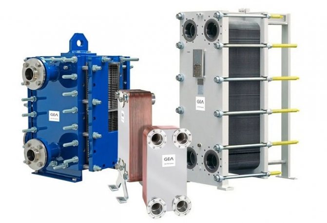
The article will discuss in detail the design, scope and principle of operation of the plate heat exchanger. Particular attention will be paid to the design features of various models, operating rules and maintenance features. In addition, a list of leading domestic and foreign manufacturers of plate TO will be presented, whose products are in high demand among Russian consumers.
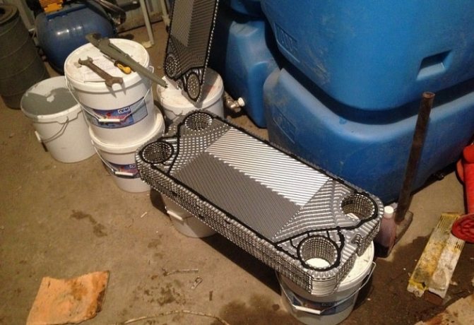
Device and principle of operation
Gasketed plate heat exchanger design includes:
- a stationary front plate on which the inlet and outlet pipes are mounted;
- fixed pressure plate;
- movable pressure plate;
- package of heat transfer plates;
- seals made of heat-resistant and resistant to aggressive media material;
- upper supporting base;
- bottom guide base;
- bed;
- set of tie bolts;
- A set of support legs.
This arrangement of the unit ensures the maximum intensity of heat exchange between the working media and the compact dimensions of the device.
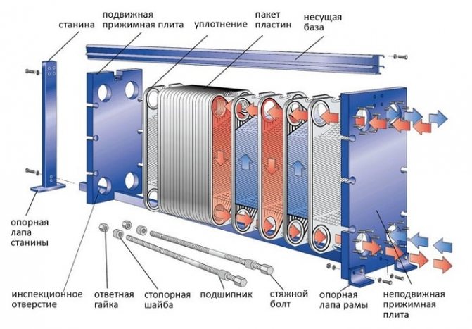
Gasketed plate heat exchanger design
Most often, heat exchange plates are made by cold stamping from stainless steel with a thickness of 0.5 to 1 mm, however, when using chemically active compounds as a working medium, titanium or nickel plates can be used.
All plates included in the working set have the same shape and are installed sequentially, in a mirror image. This method of installing heat transfer plates provides not only the formation of slotted channels, but also the alternation of the primary and secondary circuits.
Each plate has 4 holes, two of which ensure the circulation of the primary working medium, and the other two are insulated with additional contour gaskets, excluding the possibility of mixing the working media. The tightness of the connection of the plates is ensured by special contour gaskets made of a material that is heat-resistant and resistant to the effects of active chemical compounds. Gaskets are installed in the profile grooves and fixed with a clip lock.
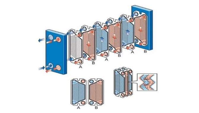
The principle of operation of the plate heat exchanger
Evaluation of the effectiveness of any plate maintenance is carried out according to the following criteria:
- power;
- the maximum temperature of the working environment;
- bandwidth;
- hydraulic resistance.
Based on these parameters, the required heat exchanger model is selected. In gasketed plate heat exchangers, it is possible to adjust the throughput and hydraulic resistance by changing the number and type of plate elements.
The intensity of heat exchange is due to the flow regime of the working medium:
- with a laminar flow of the coolant, the intensity of heat transfer is minimal;
- the transient mode is characterized by an increase in the intensity of heat transfer due to the appearance of vortices in the working environment;
- the maximum intensity of heat transfer is achieved with turbulent movement of the coolant.
The performance of the plate heat exchanger is calculated for a turbulent flow of the working medium.
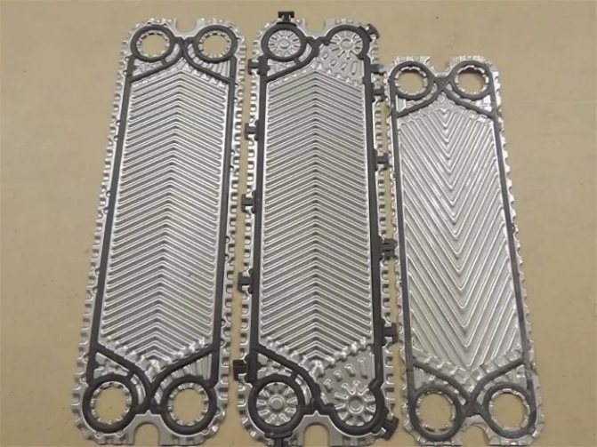
Depending on the location of the grooves, there are three types of heat transfer plates:
- with "Soft"
channels (grooves are located at an angle of 600). Such plates are characterized by insignificant turbulence and low intensity of heat transfer, however, "soft" plates have minimal hydraulic resistance; - with "Average"
channels (corrugation angle from 60 to 300). The plates are transitional and differ in average turbulence and heat transfer rates; - with "Tough"
channels (corrugation angle 300). Such plates are characterized by maximum turbulence, intense heat transfer and a significant increase in hydraulic resistance.
To increase the efficiency of heat exchange, the movement of the primary and secondary working medium is carried out in the opposite direction. The process of heat exchange between the primary and secondary working media is as follows:
- The coolant is supplied to the inlet pipes of the heat exchanger;
- When working media move along the corresponding circuits formed from heat exchange plate elements, intense heat transfer occurs from the heated medium being heated;
- Through the outlet pipes of the heat exchanger, the heated coolant is directed to its intended purpose (to heating, ventilation, water supply systems), and the cooled coolant again enters the working area of the heat generator.
The principle of operation of the plate heat exchanger
To ensure efficient operation of the system, complete tightness of the heat exchange channels is required, which is provided by gaskets.
Plate arrangement
The design and principle of operation of the plate heat exchanger will depend on the modification of the equipment, which may contain a different number of plates with fixed gaskets. These gaskets cover the channels with the flowing thermal carrier. To achieve the required tightness of the adhesion of pairs of interconnected gaskets, it is sufficient to attach these plates to a movable plate.
The loads that act on this device are distributed, as a rule, on the plates and seals. The frame and fasteners are, by and large, the body of the equipment.
The embossed surface of the plates during compression guarantees a strong attachment and allows the entire heat exchanger system to gain the necessary strength and rigidity.
The gaskets are fixed to the plates with a clip-on connection. It must be said that the gaskets are self-centered relative to their axis during clamping. Leakage of the thermal medium is prevented by the cuff edging, which additionally creates a barrier.
For the device of the plate heat exchanger, several types of seals are made: with hard and soft corrugations.
More about heat exchange equipment:
In soft plates, the channels are at an angle of 30 degrees. This type of device is characterized by high thermal conductivity, but insignificant resistance to the pressure of the heat carrier.
In rigid elements, an angle of 60 degrees is made during the manufacture of grooves. These devices are not characterized by increased thermal conductivity; their main advantage is the ability to withstand significant pressure of the coolant.
To achieve the best heat transfer mode, you can combine the plates. Moreover, it should be borne in mind that for optimal operation of the device, it is necessary that it function in the turbulence mode - the heat carrier must move through the channels without any delays. By the way, a shell-and-tube heat exchanger, where the structure has a pipe-in-pipe scheme, has a laminar flow of the coolant.
What is the advantage? During the same heat engineering characteristics, the plate equipment has significantly smaller dimensions.
Requirements for gaskets
To ensure complete tightness of the profile channels and prevent leakage of working fluids, the sealing gaskets must have the necessary temperature resistance and sufficient resistance to the effects of an aggressive working environment.
The following types of gaskets are used in modern plate heat exchangers:
- ethylene propylene (EPDM). They are used when working with hot water and steam in the temperature range from -35 to + 1600С, unsuitable for fatty and oily media;
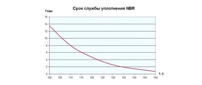
- NITRIL gaskets (NBR) are used to work with oily working media, the temperature of which does not exceed 1350C;
- VITOR gaskets are designed to work with aggressive media at temperatures no more than 1800C.
The graphs show the dependence of the service life of the seals on the operating conditions:
With regard to attaching the gaskets, there are two ways:
- on glue;
- with a clip.
The first method, due to the laboriousness and duration of laying, is rarely used, in addition, when using glue, the maintenance of the unit and the replacement of seals are significantly complicated.
The clip lock provides quick installation of plates and easy replacement of broken seals.
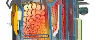
Cast iron heat exchanger
The heat exchanger is made of cast iron, does not corrode, but requires careful maintenance and careful operation. These features result from their properties of cast iron and the main thing is the fragility of cast iron. Uneven heating, which most often occurs due to scale, leads to cracks in the heat exchanger.
Information: Flushing the coolant is an obligatory and basic element of the technical operation of a gas boiler. The coolant is being flushed
- Once a year, if used as a heat carrier - running water (not recommended),
- Once every 2 years, if used - antifreeze,
- Once every 4 years, if purified water is used.
Specifications
Generally, the technical characteristics of a plate heat exchanger are determined by the number of plates and the way they are connected. Below are the technical characteristics of gasketed, brazed, semi-welded and welded plate heat exchangers:
| Working parameters | Units | Collapsible | Brazed | Semi-welded | Welded |
| Efficiency | % | 95 | 90 | 85 | 85 |
| Maximum working medium temperature | 0C | 200 | 220 | 350 | 900 |
| Maximum pressure of the working medium | bar | 25 | 25 | 55 | 100 |
| Maximum power | MW | 75 | 5 | 75 | 100 |
| Average period of operation | years old | 20 | 20 | 10 — 15 | 10 — 15 |
Based on the parameters given in the table, the required heat exchanger model is determined. In addition to these characteristics, one should take into account the fact that semi-welded and welded heat exchangers are more adapted to work with aggressive working media.
Selection of plate heat exchangers by technical characteristics
When choosing a heat exchanger, pay attention to:
- the desired temperature for heating the liquid;
- the maximum temperature of the coolant;
- pressure;
- coolant consumption;
- the required flow rate of the heated liquid.
Manufacturers produce equipment with various technical characteristics. For example, the products of the popular Alfa Laval brand have the following parameters.
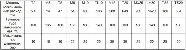
Dedicated software and specialist services simplify the search task. Typically, the units are configured to leave a liquid with a temperature of 70 ° C.
Applications
Reliable and efficient plate heat exchangers are used in various fields.
- Oil industry. The equipment is used to cool recyclable energy resources.
- Heating and hot water systems. The units heat the liquids supplied to consumers.
- Mechanical engineering and metallurgy.The equipment is used to cool machines and equipment.
- Food industry. Heat exchangers, for example, are part of pasteurization plants.
- Shipbuilding. Appliances cool various equipment and heat seawater on ships.
This is only a small part of the scope of application of heat exchangers. The equipment is also used in the automotive industry, in the production of acids and alkalis, and in other industries.
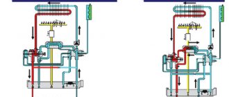
What is a heat exchanger in a heating system for?
Explaining the presence of a heat exchanger in a heating system is quite simple. Most heat supply systems in our country are designed in such a way that the temperature of the coolant is regulated in the boiler room and the heated working medium is supplied directly to the radiators installed in the apartment.
In the presence of a heat exchanger, the working medium from the boiler room is dispensed with clearly defined parameters, for example, 1000C. Getting into the primary circuit, the heated coolant does not enter the heating devices, but heats the secondary working medium, which enters the radiators.
The advantage of such a scheme is that the temperature of the coolant is regulated at intermediate individual thermal stations, from where it is supplied to consumers.
Advantages and disadvantages
The widespread use of plate heat exchangers is due to the following advantages:
- compact dimensions. Due to the use of plates, the heat exchange area is significantly increased, which reduces the overall dimensions of the structure;
- ease of installation, operation and maintenance. The modular design of the unit makes it easy to disassemble and wash the elements requiring cleaning;
- high efficiency. The productivity of the PHE is from 85 to 90%;
- affordable cost. Shell-and-tube, spiral and block installations, with similar technical characteristics, are much more expensive.
The disadvantages of the plate design can be considered:
- the need for grounding. Under the influence of stray currents in thin stamped plates, fistulas and other defects can form;
- the need to use quality working environments. Since the cross-section of the working channels is small, the use of hard water or poor-quality heat carrier can lead to blockages, which reduces the rate of heat transfer.
Features and characteristics of the plates
As already mentioned many times, only stainless steel is used for the manufacture of plates - a material that is resistant to corrosion and high temperatures. The manufacturing technology of plate heat exchanger elements is stamping, which allows the manufacture of slabs of complex configuration. Plus, this allows you to preserve the basic characteristics of the material.
It is also important to consider that not all stainless steel is suitable for making plates. Only certain brands are used. The slabs themselves have an unusual shape. Special grooves are made on top of the flat surface, located in both symmetrical and chaotic order. Thanks to such a corrugated surface, the heat removal area increases and a more even distribution of heat transfer fluids is ensured.
The fastening of rubber gaskets is carried out directly on the plates using special clips. Plus, the gaskets have a self-centering design, which is very convenient, and thanks to the cuffs, an additional barrier is created that helps to keep the coolant. If we consider the types of plates produced by manufacturers, then there are only two of them.
- Element with thermally rigid corrugation... The grooves on such a plate are made at an angle of 30 degrees. They have high heat-conducting characteristics, but do not withstand too much pressure when circulating the coolant.
- Thermally soft corrugation plate, executed at an angle of 60 degrees. Such an element has a low thermal conductivity, but easily resists the high pressure of the coolant circulating inside the unit.
Thanks to the combination of different types of plates inside the main body of the device, it is possible to achieve an optimal heat transfer option for the entire structure as a whole. However, for the efficient operation of the plate heat exchanger, it is important that the coolant circulates in a turbulent state. Simply put, the liquid inside the unit with maximum heat transfer should flow unhindered.
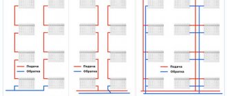
Plate heat exchanger piping diagrams
There are several ways to connect the PHE to the heating system. The simplest is considered to be parallel connection with a control valve, the schematic diagram of which is shown below:
Parallel connection diagram of PHE
The disadvantages of such a connection include an increased load on the heating circuit and a low efficiency of water heating with a significant temperature difference.
Parallel connection of two heat exchangers in a two-stage scheme will ensure more efficient and reliable operation of the system:
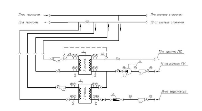
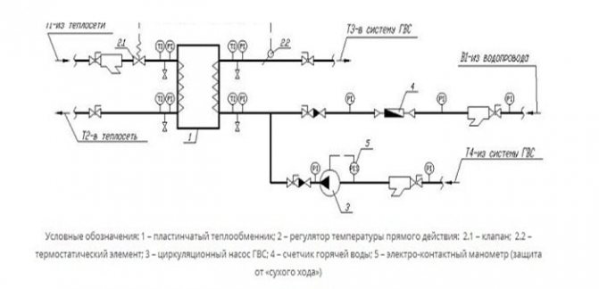
Two-stage parallel connection diagram
1 - plate heat exchanger; 2 - temperature regulator; 2.1 - valve; 2.2 - thermostat; 3 - circulation pump; 4 - hot water consumption meter; 5 - manometer.
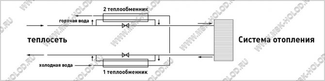
The heating medium for the first stage is the return circuit of the heating system, and cold water is used as the medium to be heated. In the second circuit, the heating medium is the heat carrier from the direct line of the heating system, and the preheated heat carrier from the first stage is used as the heated medium.
DHW heat exchanger connection diagrams
The water-water heat exchanger has several connection options. The primary circuit is always connected to the distribution pipe of the heating network (urban or private), and the secondary circuit to the water supply pipes. Depending on the design, a parallel single-stage DHW (standard), two-stage mixed or two-stage series DHW can be used.
The connection diagram is determined in accordance with the norms of "Designing of heat points" SP41-101-95. In the case when the ratio of the maximum heat flow to DHW to the maximum heat flow to heating (QHWMax / QTEPLmax) is determined within the limits of ≤0.2 and ≥1, a single-stage connection scheme is taken as a basis, if the ratio is determined within 0.2≤ QHWSmax / QTEPLmax ≤1, then the project uses a two-stage connection scheme.
Standard
The parallel connection scheme is considered to be the simplest and most economical to implement. The heat exchanger is installed in series with respect to the control valves (shut-off valve) and parallel to the heating network. To achieve high heat transfer, the system requires a large flow rate of the heat carrier.

Two-stage
When using a two-stage heat exchanger connection scheme, water heating for hot water supply is carried out either in two independent devices, or in a monoblock installation. Regardless of the network configuration, the installation scheme becomes much more complicated, but the system efficiency increases significantly and the coolant consumption decreases (up to 40%).
Water preparation is carried out in two stages: the first uses the heat energy of the return flow, which heats the water to about 40 ° C. At the second stage, the water is heated up to the normalized values of 60 ° C.
The two-stage mixed connection system is as follows:

Two-stage serial connection diagram:
A serial connection scheme can be implemented in one DHW heat exchanger.This type of heat exchanger is a more complex device in comparison with standard ones and its cost is much higher.
User's manual
Each factory-made plate heat exchanger must be accompanied by a detailed operating manual containing all the necessary information. Below are some basic provisions for all types of VET.
Installation of PHE
- The location of the unit must provide free access to the main components for maintenance.
- The fastening of the supply and discharge lines must be rigid and tight.
- The heat exchanger should be installed on a strictly horizontal concrete or metal base with sufficient bearing capacity.
Commissioning works
- Before starting the unit, it is necessary to check its tightness according to the recommendations given in the technical data sheet of the product.
- At the initial start-up of the installation, the rate of temperature rise should not exceed 250C / h, and the pressure in the system should not exceed 10 MPa / min.
- The procedure and scope of commissioning work must clearly correspond to the list given in the unit's passport.
Operation of the unit
- In the process of using the PHE, the temperature and pressure of the working medium must not be exceeded. Overheating or increased pressure can lead to serious damage or complete failure of the unit.
- To ensure intensive heat exchange between the working media and increase the efficiency of the installation, it is necessary to provide for the possibility of cleaning the working media from mechanical impurities and harmful chemical compounds.
- Significantly extending the service life of the device and increasing its productivity will allow regular maintenance and timely replacement of damaged elements.
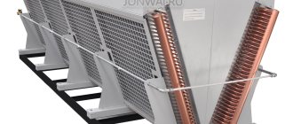
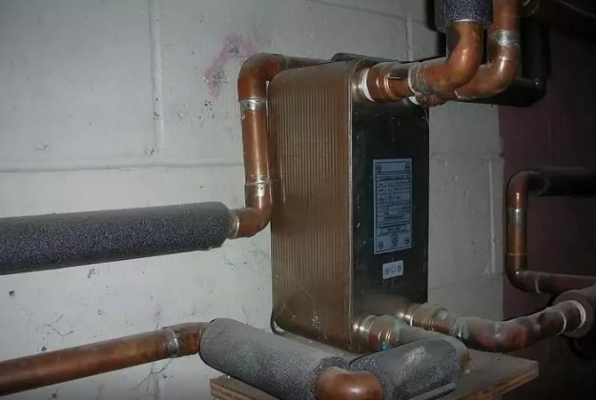
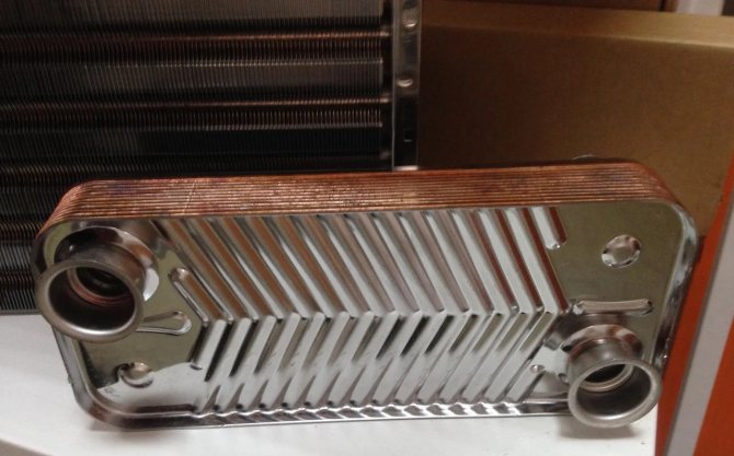
Secondary heat exchanger for gas boiler
It is also called a heat exchanger for hot water supply (DHW). This is a rectangular device with interconnected food-grade stainless steel inner plates. The more there are, the higher the performance of the unit. Inside, they form 8 to 30 layers. The high thermal conductivity of the materials and the large interaction area provide the necessary heat transfer during the rapid movement of water.
Each of the layers is a channel isolated within the heat exchanger. The plates have a relief from which these passages are formed. The thickness of the baffles is usually 1 mm. The channels have corners, and the sharper they are, the higher the fluid velocity and vice versa. The pattern of water movement can be single- and multi-way - with a change in direction. In the second case, higher efficiency is achieved.
The secondary exchanger should be washed annually with poor water quality and once every three years if you use a softener filter for it.
After opening the hot water valve on the mixer, the three-way valve directs part of the heated coolant to the secondary exchanger. Then the hot liquid gives off heat to the cold tap water in the unit, after which the heated water comes out of the heat exchanger for supply through the faucets in the kitchen and bathroom.
The cooled coolant then goes into the pipe, where it mixes with the return flow - the spent coolant from the heating system, and again enters the primary exchanger.
The secondary heat exchanger is usually located below the combustion chamber. In different boilers, it is mounted vertically or horizontally on its side.
Combined heat exchangers - bithermal - are also used in boilers. In them, communication with hot water is surrounded by channels with a heat carrier for the heating system. First, the gas transfers energy to the coolant, and then the latter directs part of it to the hot water supply. Since gas boilers with such heat exchangers are simpler, a three-way valve is not needed.
Secondary heat exchanger repair
Secondary heaters are often clogged, especially models with narrow channels.Without cleaning, they break down over time and finally fail. The scale layer inside the unit reduces heat transfer, which is why the boiler consumes more gas.
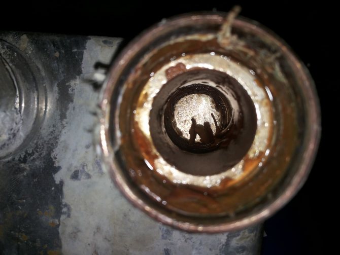
Salt deposits, scale and rust form the bulk of the pollution: in addition to the secondary heat exchanger, it does not hurt to also check the heating and DHW circuits
Problems with heat exchangers will be reported by codes on the boiler display. In this case, there is a plan of action.
Let's take a closer look at the problem with the secondary heater:
- We take out the secondary heat exchanger.
- We look at the joints, internal and external threads. After the last cleaning, their condition may have worsened. This happens due to aggressive acids. We replace the worn-out removable elements.
- We check the integrity. A water hammer could have occurred with the heat exchanger. A very small fistula (hole) can only be found by a specialist.
- We examine the exchanger better, and for this we call the wizard. We replace a badly damaged unit.
- At the very beginning, pollution can be found. We look for plaque visually in the entrance holes. We blow air into the part and also orient ourselves by sound. We clean if the exchanger is clogged. Lumps of limescale can fall out even after a light knock.
- You need to choose 1 of 3 cleaning options: home remedies such as detergents and citric acid solutions, special mixtures, or professional cleaning.
First of all, flush the exchanger with a cold tap water. Then pour citric acid into the device and place in a bucket of water. Then - take out the heat exchanger and fill it with water to check the patency.
If it comes in slowly or does not move, then prepare a saturated solution of vinegar in water and pour in there. Then rinse with hot water and blow. Use an air pump whenever possible. Repeat the vinegar cycle.
Among the arguments for professional cleaning, it is worth noting the inconvenience of the design for cleaning, the difficulty in assessing contamination, the risk of damage due to independent mechanical action.
If the steps above do not work, try a special cleaning solution, such as a cleaning gel or a low percent adipic acid solution. If this method did not work either, then call the master or order a professional cleaning.
How to replace a part?
No special knowledge is needed for this. To remove the old exchanger for inspection or replacement, follow these steps:
- Disconnect the power supply and turn off the gas.
- Remove the front cover of the boiler.
- Shut off the cold water supply for the DHW circuit. Close the valves on the flow and return pipes of the heating circuit.
- Remove the drain plug. Drain all water from the boiler.
- Reduce the pressure in the system, if necessary, and remove the air.
- Pull out the electronic board. Remove the necessary fasteners for this.
- Remove the terminals from the gas valve.
- Get out the boiler elements that prevent easy removal of the secondary heat exchanger: cold water inlet, water fittings, etc. Remove the corresponding brackets, nuts and clamps.
- Insulate all electrical assemblies and wires with waterproof material.
- Unscrew the fasteners holding the secondary heat exchanger. Use a handy tool. Sometimes this can be done with a hexagon. Manufacturers try to place the exchanger in a convenient place so that the boiler elements do not suffer during its removal.
- Remove secondary heat exchanger, remove water from there.
At the time of removal, it is worth remembering the location of the exchanger in order to install it back in the same way or put a new one.
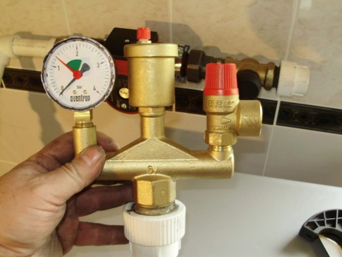
Heating system safety group: navigate by the pressure gauge (left) and in the case of readings, so-called. red zone, bleed air through the vent (in the middle)
Apply copper grease to the connections that secure the unit to the inside of the boiler. This will protect it from oxidation.
Also, replace worn seals before putting the part back in place.
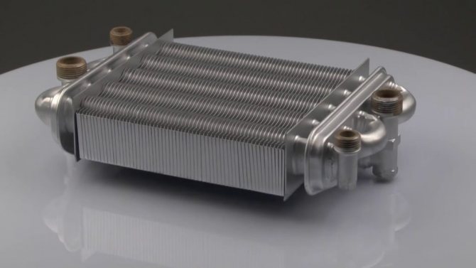
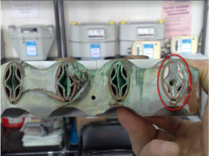
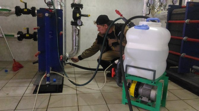
Plate heat exchanger flushing
The functionality and performance of the unit largely depends on high-quality and timely flushing. The frequency of flushing is determined by the intensity of work and the characteristics of technological processes.
Treatment methodology
Scale formation in heat exchange channels is the most common type of PHE contamination, leading to a decrease in the intensity of heat exchange and a decrease in the overall efficiency of the installation. Descaling is carried out using chemical rinsing. If other types of contamination are present besides scale, it is necessary to mechanically clean the heat exchanger plates.
Chemical washing
The method is used for cleaning all types of PHE, and is effective when the working area of the heat exchanger is slightly contaminated. For chemical cleaning, disassembly of the unit is not required, which significantly reduces the time of work. In addition, no other methods are used to clean brazed and welded heat exchangers.
Chemical flushing of heat exchange equipment is carried out in the following sequence:
- a special cleaning solution is introduced into the working area of the heat exchanger, where, under the influence of chemically active reagents, intensive destruction of scale and other deposits occurs;
- ensuring the circulation of the detergent through the primary and secondary circuits of the TO;
- flushing of heat exchange channels with water;
- draining cleaning agents from the heat exchanger.
During the chemical cleaning process, special attention should be paid to the final flushing of the unit, since the chemically active components of the detergents can destroy the seals.
The most common types of contamination and cleaning methods
Depending on the operating media used, temperature conditions and pressure in the system, the nature of the contamination can be different, therefore, for effective cleaning, it is necessary to choose the right detergent:
- descaling and metal deposits using solutions of phosphoric, nitric or citric acid;
- inhibited mineral acid is suitable for removing iron oxide;
- organic deposits are intensively destroyed by sodium hydroxide, and mineral deposits by nitric acid;
- grease contamination is removed using special organic solvents.
Since the thickness of the heat transfer plates is only 0.4 - 1 mm, special attention should be paid to the concentration of active elements in the detergent composition. Exceeding the permissible concentration of aggressive components can lead to destruction of the plates and gaskets.
The widespread use of plate heat exchangers in various branches of modern industry and utilities is due to their high performance, compact dimensions, ease of installation and maintenance. Another advantage of the PHE is the optimal price / quality ratio.
Principle of operation
If we consider how a plate heat exchanger works, then its principle of operation cannot be called very simple. The plates are turned to each other at an angle of 180 degrees. Most often, one package contains two pairs of plates, which create 2 collector circuits: the inlet and outlet of the heat carrier. Moreover, it must be borne in mind that the steam that is on the edge is not involved during heat exchange.
Today, several different types of heat exchangers are manufactured, which, depending on the mechanism of operation and design, are divided into:
- two-way;
- multi-circuit;
- single-circuit.
The principle of operation of a single-circuit apparatus is as follows.The circulation of the coolant in the device along the entire circuit is carried out permanently in one direction. In addition, a countercurrent flow of heat carriers is also produced.
Multi-circuit devices are used only during a slight difference between the return temperature and the incoming heat carrier temperature. In this case, the movement of water is carried out in different directions.
More about the plate heat exchanger:
https://youtu.be/DRd3TR4DvpI
Two-way devices have two independent circuits. With the condition of constant adjustment of the heat supply, the use of these devices is most expedient.