In this article, we will discuss the different types of temperature sensors and how they can be used on a case-by-case basis. Temperature is a physical parameter that is measured in degrees. It is an essential part of any measurement process. Areas requiring accurate temperature measurements include medicine, biological research, electronics, materials research, and thermal performance of electrical products. A device used to measure the amount of heat energy that allows us to detect physical changes in temperature is known as a temperature sensor. They are digital and analog.
Main types of sensors
In general, there are two methods for obtaining data:
1. Contact... Contact temperature sensors are in physical contact with an object or substance. They can be used to measure the temperature of solids, liquids or gases.
2. Contactless... Non-contact temperature sensors detect temperature by intercepting some of the infrared energy emitted by an object or substance and sensing its intensity. They can only be used to measure temperature in solids and liquids. They are unable to measure the temperature of gases due to their colorlessness (transparency).
Sensor selection rules
The temperature sensor for underfloor heating is selected taking into account characteristics such as power, type of top covering, installation method and equipment with additional functionality.
Power
The value must certainly meet the requirements and load of the warm floor. Otherwise, the sensor will not work correctly. When the power of the heating element is greater than that of the regulator itself, it becomes necessary to additionally install a magnetic starter between them - to prevent damage to the device due to increased load.
Feature set
The warm floor is controlled by an electric unit, which allows you to adjust the operation of the heating elements. Modern controllers have such functionality as starting and de-energizing the system, adjusting temperature conditions, as well as setting the frequency of connecting and disconnecting the heating element.
Ease of use
If you think that you will not understand programming, then you should not purchase a complex device. Even taking into account all its functionality. For example, older people find it quite problematic to deal with programmable devices. They'd better choose the mechanical option.
Easy to connect
The accompanying documentation for the thermostat always indicates how to connect the underfloor heating sensor. The terminals are located at the edge on one side of the control unit. Having connected the electrical wires according to the scheme, it will be necessary to check the performance of the heating system. To do this, measure the resistance at the terminals of the temperature sensor and the heating electric cable, or connect a warm floor and increase the temperature values from zero to the indicator recommended by SNIP, that is, up to 30 ° C.
Appearance
A thermal sensor should not only be functionally understandable, but also attractive in design. Modern knobs come in a variety of colors and shapes. You can choose an option that is in harmony with the interior of the room.
Types of temperature sensors
There are many different types of temperature sensors.From simple on / off control of a thermostatic device to complex control systems of water supply, with the function of heating it, used in the processes of growing plants. The two main types of sensors, contact and non-contact, are further subdivided into resistive, voltage and electromechanical sensors. The three most commonly used temperature sensors are:
- Thermistors
- Resistance thermocouples
- Thermocouple
These temperature sensors differ from each other in terms of performance.
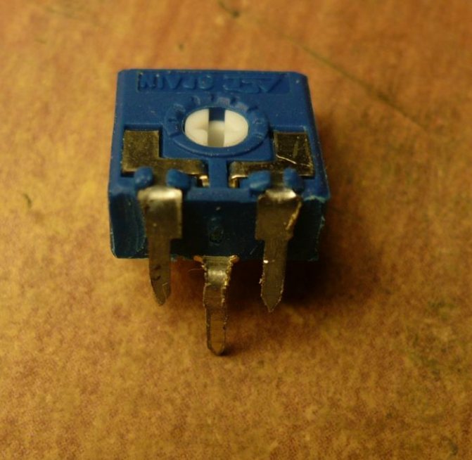
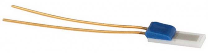
Device
This is a thermocouple (plate or rod) consisting of wires that are connected to the terminals of the sensing element.
Depending on the temperature information, the resistance of the sensitive part changes, respectively, the electrical signal supplied to the thermostat changes. Thus, the absolute value of the medium temperature is determined.

External (external temperature sensor for underfloor heating), as a rule, is located under the finishing floor covering and measures its temperature indicators. Internal (built-in), located inside the regulator and determines the level of air heating.
The design of temperature sensors is selected depending on the features of the system:
Thermistor
A thermistor is a sensitive resistor that changes its physical resistance with temperature. Typically, thermistors are made of a ceramic semiconductor material such as cobalt, manganese, or nickel oxide and are coated with glass. They are small flat sealed discs that react relatively quickly to any temperature change.
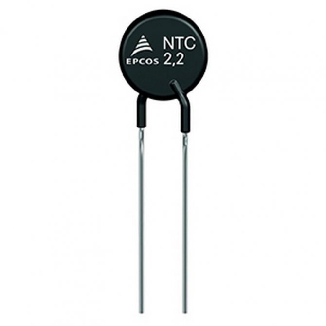
Due to the semiconducting properties of the material, thermistors have a negative temperature coefficient (NTC), i.e. resistance decreases with increasing temperature. However, there are also PTC thermistors whose resistance increases with increasing temperature.
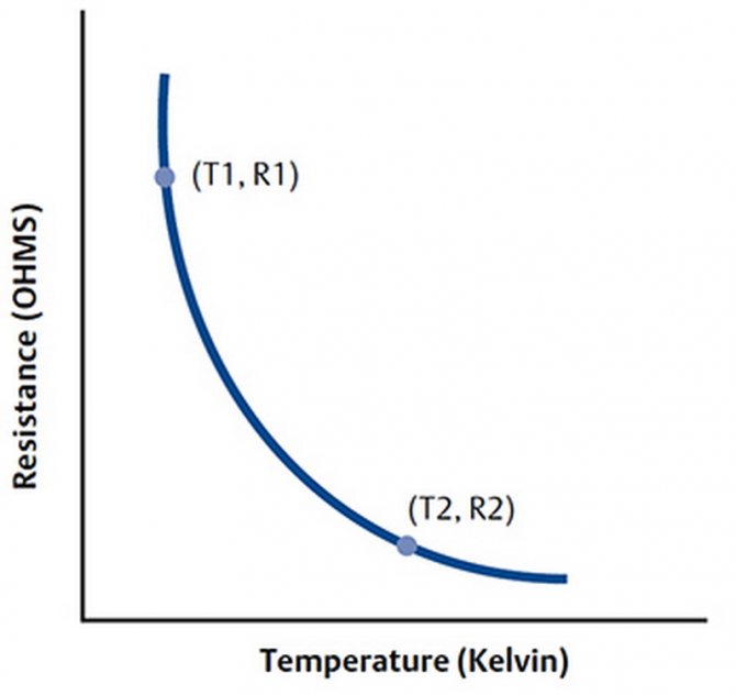
Thermistor schedule
Advantages of thermistors
- High speed of response to temperature changes, accuracy.
- Low cost.
- Higher resistance in the range of 2,000 to 10,000 ohms.
- Much higher sensitivity (~ 200 ohm / ° C) within a limited temperature range of up to 300 ° C.
Temperature dependences of resistance
The dependence of resistance on temperature is expressed by the following equation:
Where A, B, C - these are constants (provided by the terms of calculation), R - resistance in Ohms, T - temperature in Kelvin. You can easily calculate the change in temperature from a change in resistance or vice versa.
How to use a thermistor?
Thermistors are rated for their resistive value at room temperature (25 ° C). A thermistor is a passive resistive device, therefore it requires the production of monitoring the current output voltage. As a rule, they are connected in series with suitable stabilizers forming a mains voltage divider.
Example: Consider a thermistor with a resistance value of 2.2K at 25 ° C and 50 ohms at 80 ° C. The thermistor is connected in series with a 1 kΩ resistor through a 5 V supply.
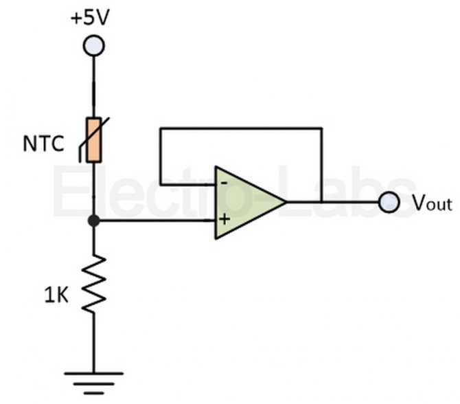
Therefore, its output voltage can be calculated as follows:
At 25 ° C, RNTC = 2200 ohms;
At 80 ° C, RNTC = 50 ohms;
However, it is important to note that at room temperature, the standard resistance values are different for different thermistors, as they are non-linear. A thermistor has an exponential temperature change, and therefore a beta constant, which is used to calculate its resistance for a given temperature. The resistor output voltage and temperature are linearly related.
Features of the two-wire current interface in LMT01 temperature sensors
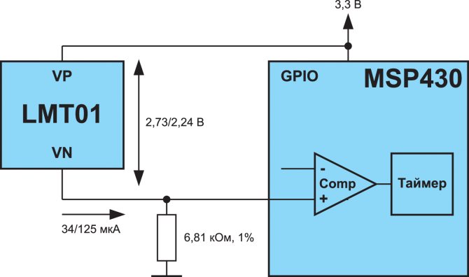
Fig. 4. Organization of the current interface with LMT01
As mentioned above, to transmit the measurement result, the LMT01 generates a bit sequence in the form of current counting pulses. For this, the sensor requires only two leads (Figure 4). To convert current pulses into the form familiar to digital microcircuits, in some cases you can use a single resistor (but not always - more on that below).
After power-up, the LMT01 starts a measurement cycle that takes up to 54 ms (Figure 5). During this time, a low level current of 28 ... 39 μA is formed at the sensor output. This is followed by a cycle of transferring the measurement result in the form of current pulses with an amplitude of 112 ... 143 μA. The receiving microcontroller must count these pulses, for example using the built-in counter / timer. Since the frequency of the signals is about 82 ... 94 kHz, then with the maximum number of pulses (4095), the transmission duration can reach 50 ms.
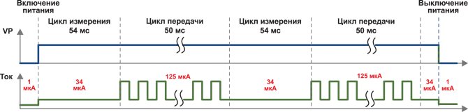
Fig. 5. Timing diagrams of LMT01 sensor operation
By the number of counted pulses (PC), the temperature value can be determined according to formula 1:
, (1)
Thus, at 0 ° C, the sensor will generate about 800 pulses.
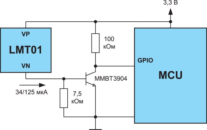
Unfortunately, using one external resistor is not always possible due to the limitation on the minimum voltage drop across the LMT01 sensor. During the measurement cycle, the drop across the sensor must be at least 2.15 V. During the data transmission cycle, the voltage drop can be reduced to 2 V. It is not difficult to make some rough calculations.
Consider a device with a supply voltage Vdd = 3.3 V. If we take the minimum allowable drop across the sensor equal to 2.15 V during the measurement cycle, then a signal of no more than 1.15 V will be observed across the resistor. For most digital controllers, the logical unit is 0 , 7 ∙ Vdd, which for our case will be 2.31 V. As a result, the use of a simple resistor turns out to be impossible, since the microcontroller simply will not "see" the signal of a logical unit. The way out of this situation can be the use of a microcontroller with a built-in comparator or level conversion circuits.
Resistive temperature sensors
Temperature-resistance sensors (RTDs) are made of rare metals, such as platinum, whose electrical resistance varies with temperature.
Resistive temperature detectors have a positive temperature coefficient and, unlike thermistors, provide high temperature measurement accuracy. However, they have poor sensitivity. Pt100 is the most widely available sensor with a standard resistance value of 100 ohms at 0 ° C. The main disadvantage is the high cost.
The advantages of such sensors
- Wide temperature range from -200 to 650 ° C
- Provide high drop current output
- More linear compared to thermocouples and RTDs
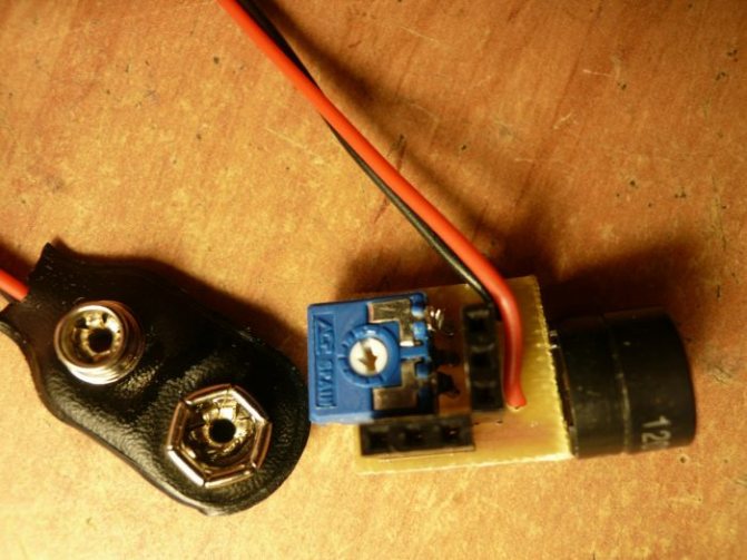
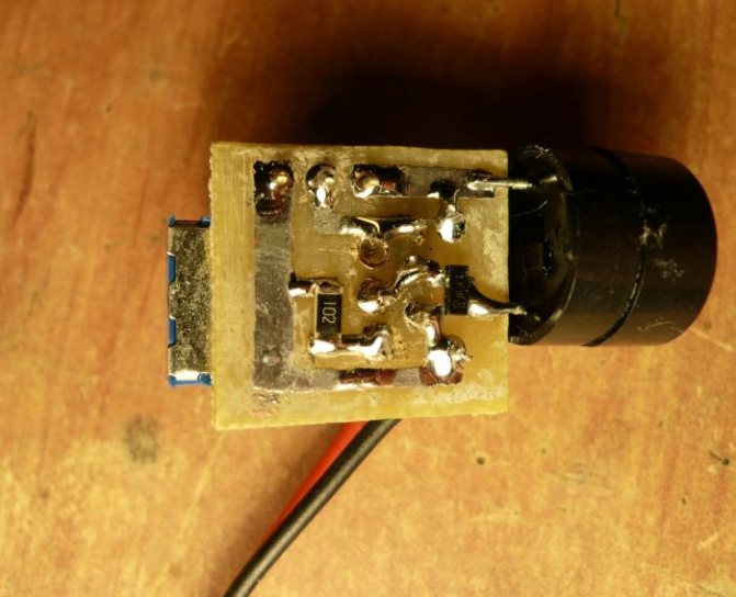
Additional components and sensor circuit
In addition to the main diode devices, the temperature sensor circuit includes a number of additional elements. First of all, it is a capacitor that protects the device from extraneous influences. The fact is that the operational amplifier is highly sensitive to the effects of alternating electromagnetic fields. The capacitor removes this dependence by inducing negative feedback.
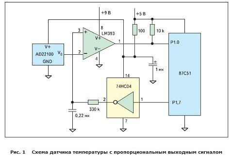
With the participation of a transistor and a zener diode, a stabilized reference voltage is formed. Here, resistors with a higher accuracy class are used with a low value of the temperature coefficient of resistance. Thereby, the whole scheme gains additional stability. In case of possible significant changes in temperature conditions, precision resistors can be omitted. They are only used to control small overheating.
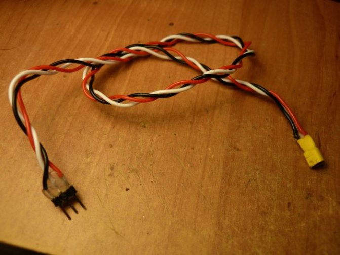
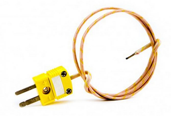
Thermocouple
Thermocouple temperature sensors are most commonly used because they are accurate, operate over a wide temperature range from -200 ° C to 2000 ° C, and are relatively inexpensive. A thermocouple with a wire and a plug in the photo below:
Thermocouple operation
A thermocouple is made of two dissimilar metals welded together to produce a potential difference over temperature. From the temperature difference between the two junctions, a voltage is generated that is used to measure the temperature. The voltage difference between the two junctions is called the Seebeck effect.
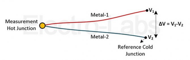
If both compounds are at the same temperature, the potential for difference in different compounds is zero, i.e. V1 = V2. However, if the junctions are at different temperatures, the output voltage relative to the temperature difference between the two junctions will be equal to their V1 - V2 difference.
Types of temperature sensors
Electronic-mechanical
The simplest and most inexpensive type of regulator. Its main working part is a special metal plate that responds to an increase or decrease in temperature. The system is switched on and off by changing the curvature of the plate during heating and cooling. Setting the exact temperature value on such a regulator will not work.
Electronic
The device has a special element that generates a special signal. The power depends directly on the values of the ambient temperature. On such devices, you can set accurate heating temperature readings up to a fraction of a degree. The system is controlled by buttons and a small screen.
Programmable
The most expensive of the thermoelements. On it, you can set certain values, upon reaching which the entire system is turned on or off by the regulator. Thanks to the device, a microclimate is created in the room that suits a particular person. It is possible to configure the thermostat so that the system is turned on at a specific time. That is, the floors are heated before the owner arrives home, and at the same time, electricity is not consumed when the owner is not.
Many models feature bright and stylish designs and LCD screens that display information and facilitate fine tuning.
Working with ready-made libraries
So, to work with DS18B20 temperature sensors on the network, you can find a huge number of libraries, but as a rule, two of the most popular are used. It is a library and a library. Moreover, the second library is a more convenient add-on over the first and cannot be used without it. In other words, before connecting the DallasTemperature.h library, you must also connect OneWire.h. How to install certain libraries in the Arduino IDE is possible.
Library OneWire.h
Let's first consider working with the OneWire.h library. Below is a list of its functions with a brief description.
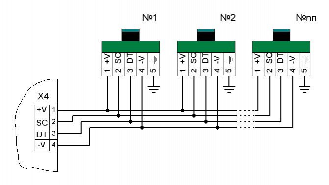
- OneWire temperatureSensor (uint8_t pinNumber)
This function is a constructor of the OneWire class and creates a temperatureSensor object, i.e. opens a communication channel with a sensor or a group of sensors on the pinNumber pin. In our examples (Figures 3-5) this is the “D2” pin of the Arduino Nano. It was to it that we connected the DQ DS18B20 data bus.
Example:
OneWire temperatureSensor
(
D2
);
// A sensor or a group of sensors is connected to pin D2
- uint8_t search (addrArray)
The function searches for the next device on the 1-Wire bus and, when it is found, enters the address value into the addrArray array, returning true. Since the unique address of each sensor is 64-bit, the addrArray must be 8 bytes in size. If the search fails, the function returns false. It should be noted that when several temperature sensors are connected to one bus, each call to the search function will be addressed to the next sensor, then the next, etc., until all devices on the bus are enumerated. The peculiarity of this function is to remember already processed addresses. To reset the queue, you need to call the reset_search () function, which will be discussed below.
Example:
byte addrArray
[
8
];
// Array for storing a 64-bit address // If the device is not present on the bus at all or all devices are enumerated // display the corresponding information in the port monitor
if(!
temperatureSensor
.
search
(
addrArray
))
Serial
.
println
(
"No more addresses."
);
// Otherwise, if the next device responded to the presence request, // display its 64-bit address in the port monitor
else{for(
i
=
0
;
i
<
8
;
i
++)
Serial
.
print
(
addrArray
[
i
],
HEX
);
}
- voidreset_search ()
As mentioned above, this function resets the polling queue of devices on the 1-Wire bus to the very beginning. It should always be used in conjunction with the search function when the latter returns false. For example, in our case with 5 sensors on the bus, by calling the search function 5 times, we can get 5 addresses. For the sixth time, the search function will return false to us and will do this with each next poll until the queue is flushed. You should pay attention to this in order to avoid incomprehensible situations.
Example:
byte addrArray
[
8
];
// Array for storing a 64-bit address // If the device is absent at all on the bus or all devices are enumerated // reset the polling queue to repeat the search cycle
if(!
temperatureSensor
.
search
(
addrArray
))
temperatureSensor
.
reset_search
();
- uint8_treset ()
The 1-Wire reset function initiates the communication process. It is called every time we want to communicate with the temperature sensor. Return values can be true or false. We will get the true value if at least one sensor on the bus responds to reset with a presence pulse. Otherwise, we get false;
Example:
if(!
temperatureSensor
.
reset
())
Serial
.
println
(
"No sensors on bus"
);else
Serial
.
println
(
"Sensor is detected"
);
- voidselect (addrArray)
The function allows you to select a specific device with which we want to work at the moment. The choice is made by explicitly specifying the 64-bit address entered in the addrArray array. The address can be set explicitly by writing it in the array or using the previously read by the search function. It should be noted that the reset function must be called before calling the select function. With the next reset, the connection with the selected sensor is broken until the next call to select.
Example:
byte addrArray
[
8
];
// Array for storing a 64-bit address // If the device is absent at all on the bus or all devices are enumerated // output the corresponding information to the port monitor
if(!
temperatureSensor
.
search
(
addrArray
))
Serial
.
println
(
"No more addresses."
);
// Otherwise, if the next device responded to the presence request, // select it for subsequent work
else{
temperatureSensor
.
reset ()
;
// Do not forget to issue the temperatureSensor reset command
.
select (addrArray)
;
// Specify an array with the read address
}
- voidskip ()
The function is relevant only when working with one sensor on the bus and simply skips the selection of the device. In other words, you can avoid using the search function, and therefore quickly get access with your only sensor.
Example:
temperatureSensor.
reset
();
// Reset the temperatureSensor tire
.
skip
();
// Select the only sensor for further work with it
- voidwrite (uint8_tbyte, uint8_t powerType = 0)
The function sends a byte of data to the selected device on the bus. The powerType argument indicates the type of power supply for the sensors (0 - sensors are powered directly from an external source; 1 - a parasitic powered connection is used). The second parameter can be omitted if external power is used, since it is 0 by default.
Example:
temperatureSensor
.
reset
();
// Reset the temperatureSensor tire
.
skip
();
// Select the only sensor for further work with it // Send a command to convert the temperature, // using a connection with parasitic power from the temperatureSensor data bus
.
write
(
0x44
,
1
);
- uint8_tread ()
This function reads one byte of data sent by the slave device (sensor) to the 1-Wire bus.
Example:
// Read 9 bytes of data from the 1-Wire bus and put the result into array byte array
[
9
];for(
uint8_t i
=
0
;
i
<
9
;
i
++){
array
[
i
]=
temperatureSensor
.
read
();}
- static uint8_t crc8 (const uint8_t * addr, uint8_t len);
The function is designed to calculate the checksum. Designed to check the correct communication with the temperature sensor. Here addr is a pointer to the data array, and len is the number of bytes.
Example:
byte addrArray
[
8
];
// Array for storing a 64-bit address // If the device is absent at all on the bus or all devices are enumerated // output the corresponding information to the port monitor
if(!
temperatureSensor
.
search
(
addrArray
))
Serial
.
println
(
"No more addresses."
);
// Otherwise, if the next device responded to the presence request, // check the checksum of its address
else{
// If the checksum does not match, display an error message
if(
OneWire
::
crc8
(
addrArray
,
7
)!=
addrArray
[
7
]){
Serial
.
println
(
"CRC is not valid!"
);}}
We examined each function of the OneWire.h library separately and in order to fix the material, below I will give a sketch for reading the temperature from a group of DS18B20 temperature sensors, which will be connected to pin D2 using a parasitic power circuit. The sketch will contain detailed comments on all the necessary points.
#include // We connect the library for working with DS18B20OneWire ds thermal sensors
(
2
);
// A sensor or group of sensors is connected to the D2 pin of the Arduino // PRESET FUNCTION void setup
(
void
){
Serial
.
begin
(
9600
);
// Initialization of work with Serial-port} // MAIN CYCLE void loop
(
void
){
byte i
;
// Auxiliary variable for byte present loops
=
0
;
// Variable for determining the readiness of the sensor for communication byte type_s
;
// Variable for defining the type of thermal sensor on the byte data bus
[
12
];
// Array for storing information received from the sensor byte addr
[
8
];
// Array for storing the 64-bit address of the float celsius sensor
,
fahrenheit
;
// Variables for calculating the temperature // If devices on the bus are not found or all devices on the bus are enumerated // display the corresponding information in the port monitor, reset the queue // and perform a search again, waiting 250ms
if(!
ds
.
search
(
addr
)){
Serial
.
println
(
"No more addresses."
);
Serial
.
println
();
ds
.
reset_search
();
delay
(
250
);return;}
// If the next device on the bus is found, display its unique address // in the port monitor in hex Serial
.
print
(
"ROM ="
);for(
i
=
0
;
i
<
8
;
i
++){
Serial
.
write
(
‘ ‘
);
Serial
.
print
(
addr
[
i
],
HEX
);}
// Check the checksum of the address of the found device // and if it does not match, display the corresponding information
if(
OneWire
::
crc8
(
addr
,
7
)!=
addr
[
7
]){
Serial
.
println
(
"CRC is not valid!"
);return;}
Serial
.
println
();
// Check the zero byte of the address, which contains information // about a specific type of temperature sensor. Depending on the value of the zero // byte, we display the series of the chip in the port monitor. If the zero byte contains an unknown // value, we display a message about the unknown family of the temperature sensor.
switch(
addr
[
0
]){case
0x10
:
Serial
.
println
(
"Chip = DS18S20"
);
type_s
=
1
;break;case
0x28
:
Serial
.
println
(
"Chip = DS18B20"
);
type_s
=
0
;break;case
0x22
:
Serial
.
println
(
"Chip = DS1822"
);
type_s
=
0
;break;default:
Serial
.
println
(
"Device is not a DS18x20 family device."
);return;}
ds
.
reset
();
// Reset the bus to initialize data exchange ds
.
select
(
addr
);
// Select the sensor with the current address to work with it // Send the command to convert the temperature (according to the documentation 0x44) // Do not forget about the second parameter "1", since we are transmitting data via the // line with parasitic power supply. ds
.
write
(
0x44
,
1
);
// The sensor starts conversion, which according to the documentation takes max. 750ms // To be on the safe side, we will organize a pause of ё second delay
(
1000
);
// Reset the bus again to read information from the sensor // save the response of the reset () function to the present variable for further work with it present
=
ds
.
reset
();
ds
.
select
(
addr
);
// Re-select the sensor by its address, since there was a reset pulse // The 0xBE command, according to the technical documentation, allows reading the internal memory // of the temperature sensor (Scratchpad), which consists of 9 bytes. ds
.
write
(
0xBE
);
// Read and display 9 bytes from the internal memory of the temperature sensor Serial to the port monitor
.
print
(
"Data ="
);
Serial
.
print
(
present
,
HEX
);
Serial
.
print
(
» «
);for(
i
=
0
;
i
<
9
;
i
++){
data
[
i
]=
ds
.
read
();
Serial
.
print
(
data
[
i
],
HEX
);
Serial
.
print
(
» «
);}
// Check and display the checksum of the received data in the port monitor Serial
.
print
(
"CRC ="
);
Serial
.
print
(
OneWire
::
crc8
(
data
,
8
),
HEX
);
Serial
.
println
();
// Start the process of converting the received data into the actual temperature, // which is stored in 0 and 1 bytes of read memory. To do this, we combine these two // bytes into one 16-bit number int16_t raw
=(
data
[
1
]<<
8
)|
data
[
0
];
// Before further conversion, you need to define the family to which // this sensor belongs (earlier we saved the result in the type_s variable). // Depending on the family, the temperature will be calculated differently, // since the DS18B20 and DS1822 return a 12-bit value, while the DS18S20 returns a 9-bit value
if(
type_s
){
// If the sensor belongs to the DS18S20 raw family
=
raw
<<
3
;
// default resolution is 9 bits
if(
data
[
7
]==
0x10
){
raw
=(
raw
&
0xFFF0
)+
12
—
data
[
6
];}}else{
// Determine to what measurement accuracy this sensor is configured byte cfg
=(
data
[
4
]&
0x60
);
// At lower resolutions, you can zero the least significant bits, // since they are not defined early
if(
cfg
==
0x00
)
raw
=
raw
&~
7
;
// 9 bits (conversion takes 93.75 ms)
elseif(
cfg
==
0x20
)
raw
=
raw
&~
3
;
// 10 bits (conversion takes 187.5 ms)
elseif(
cfg
==
0x40
)
raw
=
raw
&~
1
;
// 11 bits (conversion takes 375 ms) // The default precision is 12 bits (conversion takes 750 ms)
}
// Calculate and output temperature values to the celsius port monitor
=(
float
)
raw
/
16.0
;
fahrenheit
=
celsius
*
1.8
+
32.0
;
Serial
.
print
(
"Temperature ="
);
Serial
.
print
(
celsius
);
Serial
.
print
(
"Celsius,"
);
Serial
.
print
(
fahrenheit
);
Serial
.
println
(
"Fahrenheit"
);}
If everything is done correctly, then in the port monitor window we should see something like the following (Figure 6):
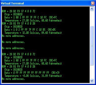
Figure 6 - the result of working with the OneWire.h library
DallasTemperature.h Library
This library is based on the previous one and simplifies the programming process a little due to more understandable functions. After installation, you will have access to 14 examples of well-documented code for all occasions. Within the framework of this article, an example of operation with one sensor will be considered.
The result of the program is shown in Figure 7
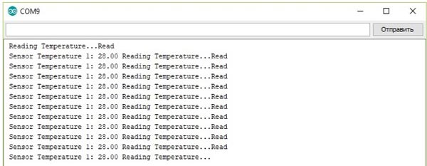
Figure №7 - the result of reading the temperature using the DallasTemperature.h library
// We connect the necessary libraries # include #include // We connect the data bus to pin # 2 of Arduino # define ONE_WIRE_BUS 2 // Create an instance of the class for our bus and a link to it OneWire oneWire
(
ONE_WIRE_BUS
);
DallasTemperature sensors
(&
oneWire
);
// PRESET FUNCTION void setup
(
void
){
Serial
.
begin
(
9600
);
// Initialize the serial port sensors
.
begin
();
// Initialize the bus
}
// MAIN CYCLE
(
void
){
Serial
.
print
(
"Reading Temperature ..."
);
// Send the command to read sensors
.
requestTemperatures
();
Serial
.
println
(
"Read"
);
Serial
.
print
(
"Sensor Temperature 1:"
);
// Display the temperature value Serial
.
print
(
sensors
.
getTempCByIndex
(
0
));}
Temperature sensor KY-001 with 1-Wire interface
This sensor is used for accurate temperature measurement. Communication with the sensor is carried out via the 1-Wire interface [1-2], which allows you to connect several similar devices to the Arduino board using one microcontroller pin [3-4]. The module is based on the ds18b20 microcircuit [5].
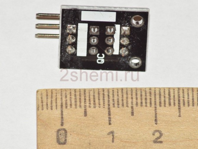
Module size 24 x 15 x 10 mm, weight 1.3 g. A three-pin connector is used for connection. Central contact - power supply + 5V, contact "-" - common, contact "S" - informational.
The board has a red LED that lights up when information is being exchanged.
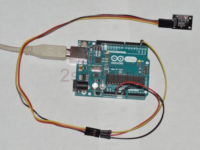
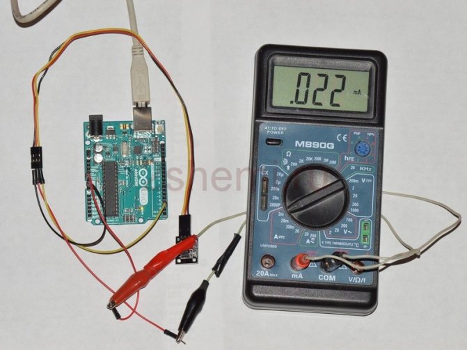
Current consumption 0.6 mA during information exchange and 20 μA in standby mode.
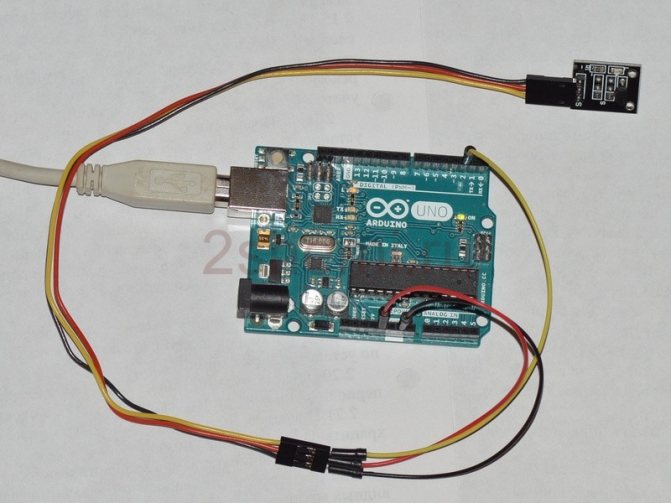
Connecting this type of sensors to Arduino is well described in many sources [6-8]. In this case, the main advantages of the Arduino are again manifested - versatility and the presence of a huge amount of reference information. To work with the sensor, you will need the OneWire Library [9]. Having loaded the program from [8] (there is an error in the first version of the program - there is no #include library connection in the code header), the following information can be observed in the serial port monitor.

The author also tested the code from [7], everything worked right away, in the serial port monitor you can read information about the type of the connected sensor and the actual temperature data.

In general, a very useful sensor that makes it possible to get acquainted with the 1-Wire interface in practice. The sensor gives the correct temperature data immediately, the user does not need to calibrate.