Calculation of the heating system make-up deaerator.
fig. 2.6. Calculation diagram of the vacuum deaerator.
opodpvd
2.10. Calculation of the HDPE system.
424dr4525dr5626dr6727dr7't
Figure 2.7. Design diagram of the HDPE system.
6t5tpsouupltdvut'prtnevozvtt7oetktoo
2.11. Determination of steam flow rate for the turbine and verification of its power.3. Thermal calculation of HDPE and optimization of its characteristics on a computer.Initial data for IPA 4:
- consumption of heated water Gw = 0.84102 = 85.7 kg / s;
- inlet water temperature tv1 = 136 ° C;
- heating steam pressure P = 0.52 MPa;
- heating steam saturation temperature tн = 153 оС;
- temperature head of the heater t = 2 оС
- latent heat of vaporization r = 2102 kJ / kg;
- average heat capacity of water av = 4.19 kJ / kg oC;
- inner diameter of pipes dvn = 0.018 m;
- pipe thickness = 0.001m;
- thermal conductivity of brass st = 85 W / m K;
- distance between partitions H = 1 m;
- water speed c = 2 m / s;
- the price of a ton of fuel equivalent, central fuel = $ 60 / ton of fuel equivalent;
- specific cost of the heater surface kF = 220 $ / m2;
- the coefficients of the heat extraction value j + 1 = 0.4 and j = 0.267;
- the number of hours of using the installed power hsp = 6000 h;
- Boiler efficiency ka = 0.92;
- Heat flow efficiency tp = 0.98.
LtdPhysical properties of water at tвf.
322
Physical properties of the condensate film at tn.
3222ooo2ntr
4. Determination of the coefficients of the value of heat.Calculation of power change factors.The coefficients of the heat extraction value are calculated by the formula:Analysis of technical solutions using CCT selections.
- Decrease of the temperature head in LDPE 6 by 1 ° C.
- Superheated steam cooler installation.
- Installation of a drainage pump on HDPE 2.
- Installing the expander.
- Increase of pressure losses in the selection pipeline to LPH 4 by 2 times.
Ltd
- Have
Installation of a drainage cooler on a high pressure pump 6.
5. Calculation of technical and economic indicators.6. Choice of auxiliary equipment of the turbine plant.
- We select feed pumps to supply feed water at the maximum power of the installation with a margin of 5%:
pnpv
- We select condensate pumps according to the maximum steam flow into the condenser with a margin:
cnc
- We select drainage pumps without a reserve (reserve - cascade drain) of the KS-32-150 type (PND 6).
- We select low pressure heaters of PN-200-16-7 I type in the amount of 4 pieces.
- High pressure heaters in the amount of three pieces of type PV-425-230-35-I.
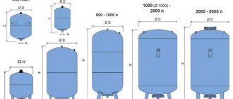
- Deaerators are selected with a DP-500M2 type deaerator column and a BD-65-1 type deaerator tank.
Conclusion.
o2
Literature.
2
Read online "Rules for the technical operation of thermal power plants" - RuLit - Page 27
6.2.53. The heating network is replenished with softened deaerated water, the quality indicators of which correspond to the quality requirements for the network and makeup water of hot-water boilers, depending on the type of heat source and heat supply system.
6.2.54. Recharge of heat consumption systems connected according to an independent scheme is carried out with water from the heating network.
6.2.55. The water pressure at any point in the supply line of water heating networks, heat points and at the top points of directly connected heat consumption systems during operation of network pumps must be higher than the saturated steam pressure of water at its maximum temperature by at least 0.5 kgf / cm2.
6.2.56. Excessive water pressure in the return line of water heating networks during operation of network pumps must be at least 0.5 kgf / cm2. The water pressure in the return line should not be higher than the permissible one for heating networks, heating points and for directly connected heat consumption systems.
6.2.57. The non-working heating network is filled only with deaerated water and must be under an excess pressure of at least 0.5 kgf / cm2 at the upper points of the pipelines.
6.2.58. For two-pipe water heating networks, the heat supply mode is based on a schedule of central quality control.
If there is a load of hot water supply, the minimum water temperature in the supply pipeline of the network is provided for closed heat supply systems not lower than 70 ° C; for open heating systems for hot water supply - not lower than 60 ° C.
6.2.59. The temperature of the water in the supply line of the water heating network in accordance with the schedule approved for the heat supply system is set according to the average outside air temperature for a period of time within 12-24 hours, determined by the heating network manager depending on the length of the networks, climatic conditions and other factors.
Deviations from the specified mode at the heat source are provided for no more than:
by the temperature of the water entering the heating network ± 3%;
by pressure in the supply pipeline ± 5%;
by pressure in the return pipeline ± 0.2 kgf / cm2.
The deviation of the actual average daily temperature of the return water from the heating network can exceed the one set by the schedule by no more than + 5%. The decrease in the actual return water temperature compared to the schedule is not limited.
6.2.60. Hydraulic regimes of water heating networks are developed annually for heating and summer seasons; for open heat supply systems during the heating season, the modes are developed with maximum water intake from the supply and return pipelines and in the absence of water intake.
Measures to regulate the consumption of water at consumers are drawn up for each heating season.
The sequence of construction of new highways and pumping stations, provided for by the heat supply scheme, is determined taking into account the real growth of the connected heat load, for which the organization operating the heat network is developing hydraulic modes of the heat supply system for the next 3-5 years.
6.2.61. For each control point of the heating network and at the make-up nodes in the form of a regime map, the permissible values of the flow rates and pressures of water in the supply, return (and make-up) pipelines are set, corresponding to normal hydraulic modes for heating and summer periods.
6.2.62. In the event of an emergency power outage of the network and transfer pumps, the organization operating the heating network ensures the pressure in the heating networks and heat consumption systems within the permissible level. If it is possible to exceed this level, it is planned to install special devices that protect the heat supply system from water hammer.
6.2.63. Repair of heating networks is carried out in accordance with the approved schedule (plan) based on the results of the analysis of identified defects, damages, periodic inspections, tests, diagnostics and annual tests for strength and density.
The repair work schedule is drawn up on the basis of the conditions for the simultaneous repair of pipelines of the heating network and heating points.
Before carrying out repairs of heating networks, the pipelines are freed from the network water, the canals must be drained. The temperature of the water pumped out of the waste wells should not exceed 40 ° C. Draining water from the chamber of heating networks to the surface of the earth is not allowed.
6.2.64. In each organization operating heating networks (in each operational area, section), an instruction is drawn up, approved by the technical manager of the organization, with a clearly developed operational plan of action in case of an accident on any of the heating mains or pumping station in relation to local conditions and network communications.
The instruction should provide for the procedure for disconnecting highways, distribution networks and branches to consumers, the procedure for bypassing chambers and heating points, possible switchings for supplying heat to consumers from other highways and have schemes for possible emergency switching between highways.
Plans for the elimination of technological disruptions in the heating networks of cities and large settlements are coordinated with local authorities.
6.2.65. According to the developed switching schemes with the operational and operational-repair personnel of heating networks, trainings are carried out regularly according to the approved schedule (but at least once a quarter) to improve the clarity, sequence and speed of emergency operations with their reflection on the operational scheme.
6.2.66. To quickly carry out work to limit the spread of accidents in heating networks and eliminate damage, each operational area of the heating network provides the necessary supply of fittings and materials. Fittings installed on pipelines are provided of the same type in length and flanges.
The emergency stock of materials is stored in two places: the main part is stored in the pantry, and a certain amount of emergency stock (consumable) is in a special cabinet at the disposal of the responsible person from the operational personnel. Consumables used by operational personnel are replenished within 24 hours from the main part of the stock.
The stock of fittings and materials for each operational area of the heating network is determined depending on the length of the pipelines and the number of installed fittings in accordance with the emergency stock standards, a list of necessary fittings and materials is drawn up, which is approved by the person responsible for the good condition and safe operation of the organization's heating networks.
7. CONDENSATE COLLECTION AND RETURN SYSTEMS
7.1. Technical requirements
7.1.1. The systems for collecting and returning condensate to the heat source are closed. The excess pressure in the condensate collecting tanks is provided for at least 0.005 MPa (0.05 kgf / cm2). Open condensate collection and return systems are allowed when the amount of returned condensate is less than 10 t / h and the distance from the heat source is up to 0.5 km. Refusal to fully return the condensate must be justified.
7.1.2. Condensate collection and return systems use condensate heat for the organization's own needs. The refusal to use the heat of condensate must be justified.
7.1.3. The capacity of the collection tanks for condensate must be at least 10 minutes of maximum condensate flow. The number of tanks for year-round operation must be at least two, the capacity of each must be at least half of the maximum condensate flow rate. During seasonal operation, as well as at a maximum condensate flow rate of no more than 5 t / h, one tank may be installed.
2.6. Main and auxiliary equipment of cogeneration plants
The water supplied to the heating network for the needs of consumers at the CHPP is heated in the network heaters of the turbine plants, in the peak heaters and in the peak hot water boilers, which are the main heating equipment of the CHPP. The auxiliary heating equipment includes: a heating system make-up unit, network pumps, storage tanks, recirculation pumps for hot water boilers, etc.
Peak hot water boilers (PVK) are intended for installation at CHPPs in order to cover the peaks of heating loads.
Peak hot water boilers are usually installed in separate rooms at large CHP plants or in the main building at small CHP plants. The fuel for these boilers is mostly fuel oil or gas. Due to the low use during the year, peak boilers are simple in design and inexpensive. The building can be made only for the lower part of the boilers, while the upper part of them remains in the open air. Before the CHP plant is put into operation, hot water boilers can be used for temporary district heating supply to the district. The mains water is heated sequentially in the mains heaters up to 110 ÷ 120C, and then in the PVK up to 150C maximum.
In order to avoid corrosion of the boiler metal, the temperature at the inlet to it should not be lower than 50 ÷ 60C, which is achieved by recirculation and mixing of hot and cold water. The calculated efficiency of hot water boilers for gas and fuel oil reaches 91 ÷ 93%. Coal-fired PVCLs are produced and used. They have their own dust preparation, smoke exhausters and other equipment.
Steam-water heaters of heat treatment plants
are intended for heating the heating system with steam from turbines or from boilers through reduction-cooling units (abbreviated as PRU).
Network pumps
serve to supply hot water through heating networks and, depending on the place of installation, are used as pumps of the first rise, supplying water from the return pipeline to the network heaters; the second rise to supply water after the network heaters to the heating network; recirculation, installed after peak hot water boilers.
Network pumps must have increased reliability, since interruptions or malfunctions in the operation of the pumps affect the operating mode of the CHP and consumers.
The main feature of the operation of network pumps is fluctuations in the temperature of the supplied water over a wide range, which in turn causes a change in pressure inside the pump. Network pumps must operate reliably over a wide flow range.
Typically, network pumps are centrifugal, horizontal, driven by an electric motor.
Advantages and disadvantages
Each type of TP has its own advantages and disadvantages. Pros of TSC:
- coolant parameters - temperature, pressure, are maintained and controlled automatically;
- the point serves a large number of consumers.
There are many more disadvantages of this solution:
- Each consumer receives a strictly metered amount of heat. However, these shares are equal only at the TSC level. Due to the different length of the pipeline, the residents of the buildings receive water at different temperatures.
- The longer the piping, the greater the heat loss. Because of this, it is necessary to increase the temperature at the central heating station, which leads to an increase in the cost of heating and hot water.
- During the renovation, a large number of residents remain without heat.
- Hot water circulation is uneven. In houses located far from the central heating station, it takes a long time to drain cold water before getting heated. The meter counts this entire volume as hot flow.
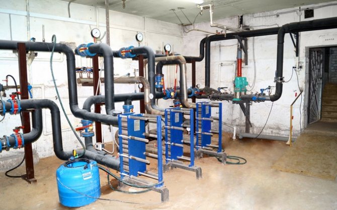
IHP in the basement of the house saves up to 30% on hot water costs
ITP is much more profitable:
- Less heat loss during heat transfer. Installing an ITP in a building saves 15 to 30% of costs.
- All apartments receive the same amount of heat, taking into account the area.
- From the tap, the water comes really hot and immediately.
- Since the heating unit operates without a high load, the probability of breakdowns is lower. Installation and repair of equipment takes less time.
- If the TP fails, fewer tenants suffer.
The disadvantages of an individual complex are associated only with its limited capabilities. TP serve 1 house, sometimes even a part of it. It will take a lot of money to modify an entire neighborhood.
The advantages and disadvantages of the MTP are determined by its purpose. However, such a system has its advantages:
- The finished module takes up a minimum of space. Even if it is a central heating station, it can be installed in the basement.
- Installation is extremely simple - you just need to connect it to the heating main and the power grid.
The higher the degree of automation of the heating unit, the lower the cost of its maintenance and service.