Why do you need a collector
In fact, the collector is a pipe with holes for the inlet and outlet of the coolant, it is also called a distribution and mixing unit. The function of the device is to maintain the required temperature level in the system and control the water flow.
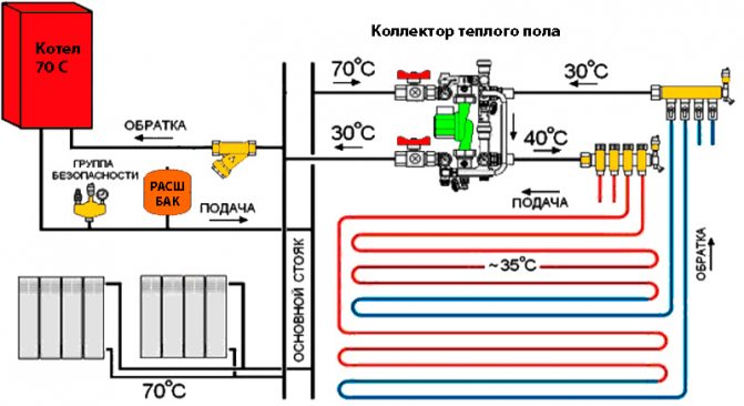
The device is designed to mix the water coming from the boiler, where it is heated, with the cooled liquid coming from the return, to the required level for underfloor heating. Indeed, in a boiler, the coolant usually warms up to +90 degrees, and for a heated floor it is a high temperature.
It requires +40 - 45 degrees, so you can't do without a collector. If water flows directly from the heat source into the circuits, this will lead to overheating of the system and its failure.
In addition, the circuits have different lengths, and they have different heat energy requirements. Therefore, a special unit is needed between the boiler and the pipeline, which will distribute the flows of hot water along the loops.
How can water floors be installed?
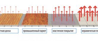
Warm water floors can be laid in different ways - flooring and using concreting. Let's take a closer look at each of them.
- Concreting Pipes through which the coolant circulates are laid in the required way on the prepared base and poured with a concrete screed. The main disadvantages: labor-intensive "wet" work, the large weight of the system and the complexity of its dismantling.
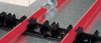
- Laying method involves laying pipes in a specially assembled flooring.
It can consist of plastic modules or wooden blocks with grooves prepared in them for mounting pipes. You can also find wooden mounting modules on sale. The main disadvantage is that the system takes longer to warm up than concrete.
Types and principle of work
Collector devices differ in the material from which they are made - brass, plastic or stainless steel. And also by the type of valve:
- With two-way - the design feature is continuous heating of the coolant. The heated water is supplied constantly, and the shut-off valves regulate its volume. As a result, the surface heats up evenly, while overheating of the system is not possible. But this model is not suitable for rooms with an area of more than 200 m2.
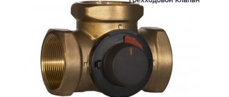
- With three-way - universal equipment, recommended for large rooms. The technology allows installation with a servo drive and various automation. The valve is capable of creating optimal operating pressure, adjusting the temperature level and the amount of the supplied coolant.
Views
In addition, there are 4 types of collectors:
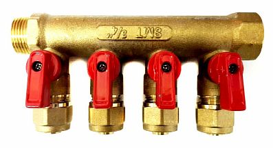
- Simple - a pipe with shut-off valves having an internal and external thread. The model is cheap, but there is no function for configuring the system. To install such a collector on warm floors, additional elements are required.
- Equipped with outlets from a valve for regulation, and valves for connecting circuits - a Chinese device. It is not uncommon for the structure to leak, but the repair is not difficult, it is enough to change the gasket. The distance between the flow and return pipes does not correspond to European standards, therefore different fixtures are required.
- With control valves and Euro-cones - an expensive model. It does not have ball valves, but there are fittings and adjustment valves, a servo can be installed on them, which will regulate the temperature in the line.
- With flow meters - they are located on the supply pipe of the collector, and sockets for servo drives are located on the back.Such a device is designed for underfloor heating with different lengths of circuits, the presence of flow meters allows you to adjust the volume of the coolant in each circuit.
Any model is equipped with outlets for the release of water and air.
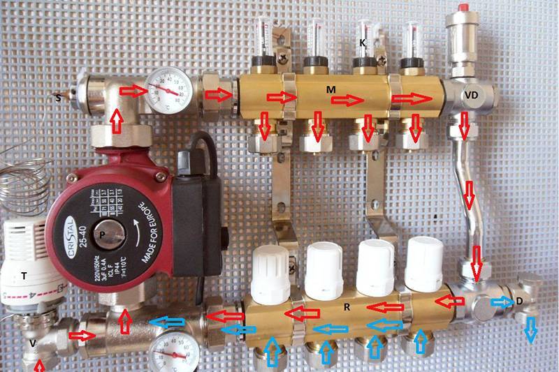
Principle of operation
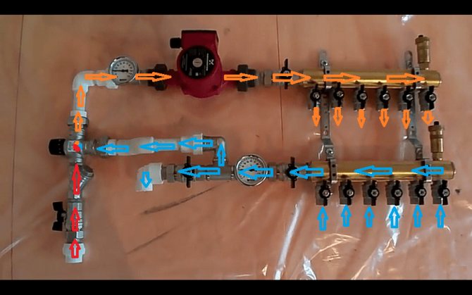
The general principle of the unit functioning, regardless of the type of valve (two or three-way), is to distribute the water flow along the loops of the heating floor, which circulates under the influence of the pump. The amount of coolant entering each branch is regulated mechanically or automatically - by a servo drive.
The work process looks like this:
- The heat carrier heated to 60 - 80 degrees is supplied from the source to the comb through the thermostatic valve;
- The chilled water flow from the return flow comes from the distributor;
- The shut-off valve has a head that regulates the temperature of the liquid;
- The mixed two streams are fed to the mixing pump, then the water is distributed through the pipelines.
When the degree of heating of the coolant in the line decreases to the required level, heated water from the source is mixed in, a two or three-way valve is responsible for this.
How are the collection departments located?
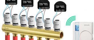
For the underfloor heating system, you can install one common collector or mount an individual device in front of each heating circuit. In this case, each manifold must be equipped with thermostats, a flow meter and three main elements:
- A mixing valve that determines the degree of heating of the heat carrier in the heating circuit.
- A radiator balancing shut-off valve connecting the manifold to the heating system. Opens and, if necessary, closes the water supply to the circuit.
- Overflow valve. It is responsible for constant pressure in the pipes, for which it directs the excess coolant into the bypass.
Assembly schemes can be very different. For a system with one radiator pipe, for example, a bypass is required. Moreover, it should always be open, so the excess of hot coolant will be discharged directly into the radiator.
If there is a return loop, bypass is not necessary. If the heated area is small, the collector compartment can be placed in the secondary circuit.
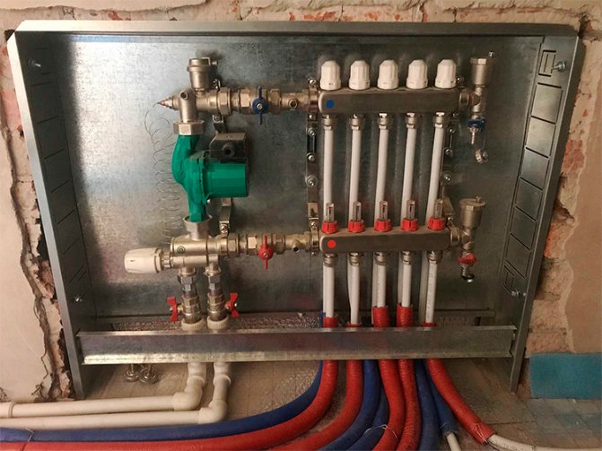
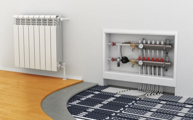
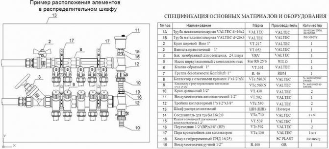
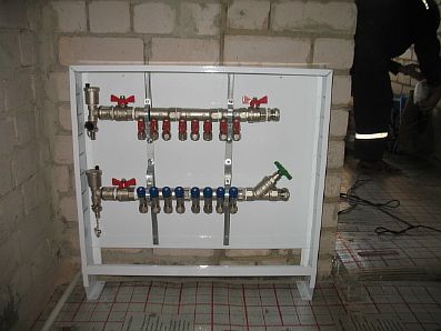
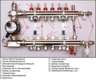
Manifold cabinet device
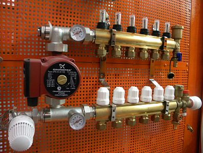
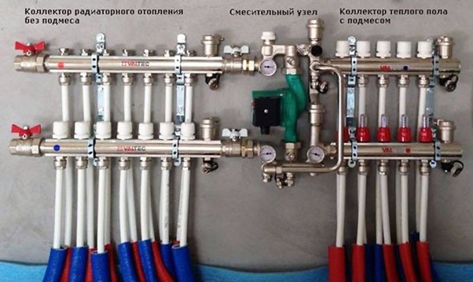
A manifold cabinet is a structure that includes a pump-mixing unit and a manifold block.
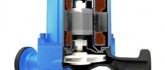
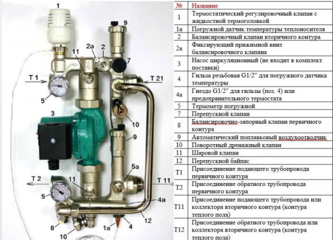
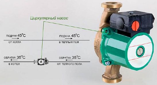
Pump-mixing unit
This unit is designed to dilute the heated water flowing into the water floor line, with the spent, cooled heat carrier. The impellers of the pump are responsible for the mixing process.
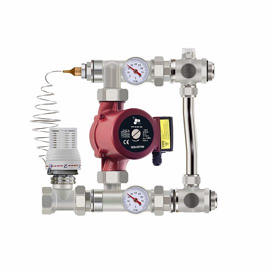
It is the pump that supplies the liquid diluted to the required degree to the system. It, moving through the pipes, gives off heat to the room and the cooling returns to the mixing unit.
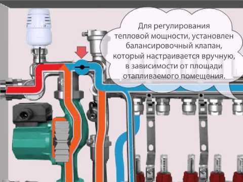
The temperature regime is adjusted using balancing valves, with their help, the flow of waste water in the pipes is also regulated. To heat a small room, the shut-off valves must be opened, if the room is small, close.
This collector circuit for underfloor heating is equipped with a thermal head, which is responsible for the temperature level in the system. It opens or closes the hot water supply plug. When the flow of the coolant stops, the bypass valve opens and the liquid moves through the free bypass.
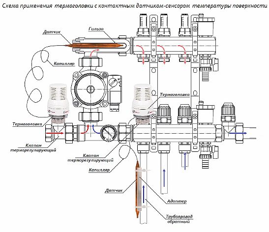
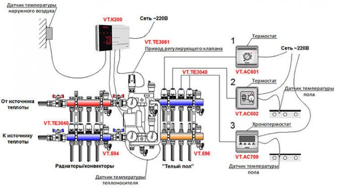
With a simple method of strapping the collector, manual temperature control is done. A servo drive with a thermostat is used to automate the process. The servo drive receives a signal from the thermostat about the temperature level in the room, and based on this indicator, it opens or closes the return manifold flap, thereby regulating the circulation of water in the floor.
The main indicators characterizing the pumping and mixing unit:
- operating pressure - maximum value 10 bar;
- temperature level - +90 degrees (maximum);
- temperature range - from 20 to 60 degrees.
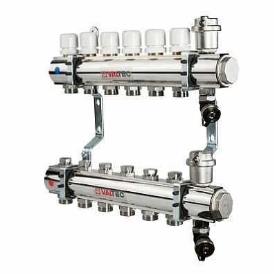
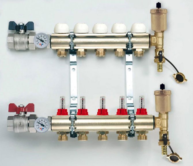
Manifold block
The manifold cabinet is equipped with a block responsible for regulating the water flow, which enters the floor line and returns back.
Technical indicators:
- product diameter - 1 or 1.25 inches;
- number of taps - from 3 to 12;
- pressure (operating value) - 10 bar;
- the maximum level of heating of the coolant is +100 degrees.
In the manifold block there are two rows of bypasses... One, the so-called straight row, is responsible for adjusting the volume of the hot coolant, the other (reverse) regulates the cooled water.
What should be done before starting installation?
A competent arrangement of a warm water floor requires careful preparatory work. In their course, all the little things must be taken into account, on which the effective functioning of the structure will subsequently depend:
It is best to entrust the project of the future system to specialists, since it is quite difficult to make independent calculations.
It will be necessary to determine the length of the pipe, the step of its installation and the power of the heating circuit, if there are several of them, then for each separately. This takes into account many nuances and parameters. There are special calculation programs that many people use.
However, you need to understand that a flaw in the calculations will lead to a decrease in efficiency or simply the impossibility of functioning of the entire system. Equipment for underfloor heating must be of high quality, manufactured and purchased from a reliable company that gives good guarantees.
It will be cheaper to pay for a quality product than to spend a lot of money for expensive and time-consuming repairs later. To minimize the heat load on the screed and prevent its cracking, the system should be divided into sections of no more than 40 square meters. m. The base for underfloor heating must be carefully prepared.
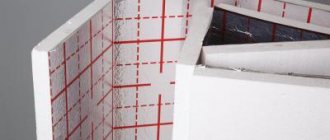
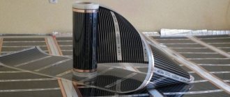
It must be clean and leveled, differences of more than 5 mm are not allowed.To prevent heat loss, a heat-insulating layer must be spread on the prepared base, with a height of 3 to 15 cm, depending on the operating temperature of the coolant. These can be special heat-insulating materials or mats designed for a warm water floor. The latter can be equipped with pipe fittings, the so-called bosses, which is very convenient.
A damper tape is laid around the perimeter of the room and between the installation areas, which can compensate for the temperature fluctuations of the screed.
Boss mats designed for water floor heating are very comfortable. They not only function as a heat insulator, but also secure the pipes in place.
When drawing up a laying scheme, a large number of pipe joints should be avoided, which carry the potential danger of leaks under the floor. It is best to equip the most secure option, where connections are present only at the outlet and inlet of the collector. In this case, the length of the one-piece pipe should not be more than 90 m, otherwise the temperature of the circulating heat carrier may drop.
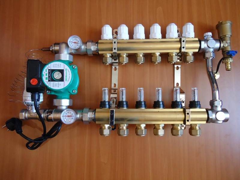
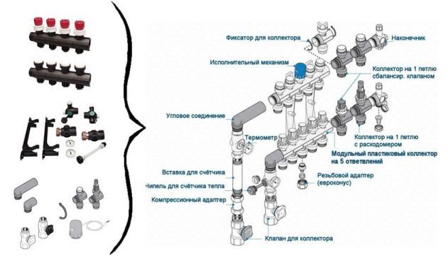
Correct assembly of the collector for underfloor heating
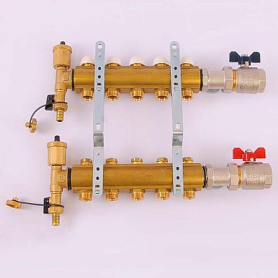
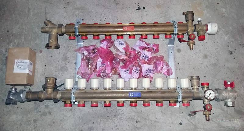
Collecting a purchased factory-made collector is a simple process. Included:
- a distributor with rotameters, it is connected to the flow - it has 2 or more outlets for circuits;
- return manifold with thermal valves instead of flow meters;
- automatic air vents;
- taps with plugs for supplying and draining water from the underfloor heating main;
- inlet and outlet temperature thermometers;
- shut-off ball valves and brackets.
When purchasing the device, its completeness can be changed, starting from the budget and the method of connection with the boiler. It is permissible to install a distributor without rotameters or 1 thermometer, not 2.
Build process
The factory device is made so that everyone could mount it with their own hands. That is, more often the distribution parts are sold already assembled, only the contours of the underfloor heating need to be connected to them, and parts that are of secondary importance must be connected.
The equipment should be assembled in stages:
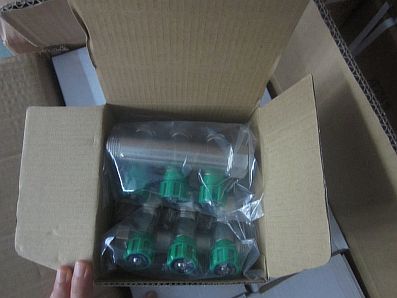
- The device is removed from the packaging. In the factory models, the flow and return pipes already have flow meters and valves. If the knot is divided into several parts, then they should be twisted together.
- The collector is fixed on a bracket, this will allow for further assembly with great convenience.
- The rest of the parts are connected - an air vent, valves, plugs and control devices.
- Ball valves are mounted on the return manifold.
The circulation pump and valves must be fixed after fixing the unit to the wall.


What is required to assemble the main distributor for TP?
The varieties, equipment and purpose of individual node elements of the collectors have already been described in the article "Choosing a collector for a warm floor: types, equipment". Therefore, here we will briefly recall that for assemblies of its various types you will need:
- a pair of basic combs (monoblock or composite) for the supply and return of the coolant;
- two-way ball valves. Two of them will be required to cut off the supply and return from the primary (radiator) heating circuit. The rest can be used as shut-off valves at the inlet / outlet of the underfloor heating circuits to the corresponding comb;
- manual valves - rotameters for balancing the flow rate of the heating agent in each branch. They are usually mounted on the supply manifold for each TP circuit;
- thermostatic valves, manual or controlled by a controller with servo drives;
- a circulating pump, which is advisable to purchase in a set of a ready-made mixing group, together with taps for connection, a bypass, a mud filter, etc. It should be noted that when installing a manifold for a warm floor with your own hands according to a simplified scheme, you can do without a pump, using only an automatic three-way valve or two-way Unibox type;
- control devices - manometers, thermometers;
- security groups;
- fittings and various connecting elements for fastening underfloor heating pipes to collectors, etc.
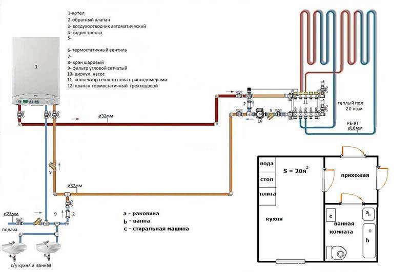
Installation of the underfloor heating collector
Having collected the main elements, you can proceed to the installation and connection of the underfloor heating collector. The process consists of several steps:
- Location and location of installation. The standard height of the collector attachment on the wall from the base of the floor is 500 - 1000 mm, it should not be installed below, since it will be difficult to connect the floor pipes to it. In addition, it should be placed so that the length of all loops is the same, and there should be free access to it, preferably in the middle of the room.
- Installing a manifold cabinet. At the planned site, a collector cabinet is being installed, usually its size is 1 by 1 m, with a wall thickness of 12 cm. It can be placed in an equipped niche or fixed directly on the wall. The surface of the wall must be flat, otherwise the structure may malfunction.
- Fastening the comb in the box. The cabinet is equipped with special guides, they can be moved to the required distance, it depends on the length of the collector. They have fasteners - bolts, with the help of which the device is fixed in the box.
- Installation of the pump and valves (two or three-way) is carried out according to the planned scheme. On the supply pipe that goes from the boiler, a valve with a thermal head is first mounted, then the pump is installed on flanges with union nuts, it must be placed between the valve and the manifold. It is impossible to install the pump in front of the shut-off valves, then the valve will not function, and the water will not flow correctly.
Connecting the TP to the collector
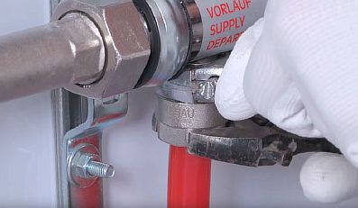
It is necessary to connect the contours of the underfloor heating to the taps of the comb using a threaded connection under the Eurocone. More often, the Eurocone has a diameter of 17 mm, while the floor hose is 16 mm.Therefore, you will need to calibrate it for this size. Then:
- it is necessary to put the union nut on the tube, insert the compression ring and the thrust sleeve;
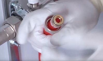
- manually connect the end of the hose to the comb fitting;
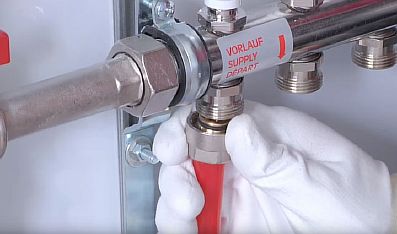
- finally tighten with two wrenches - one fixes the hexagon on the fitting, the other tightens the connection.
Collector setup
The process of setting up a collector for a water underfloor heating is done according to the following instructions:
- removing the cap from the valves;
- fixing the valve with a hexagon;
- determination of the number of revolutions for a specific loop;
- scrolling the valve by the calculated number of times.
The rest of the contours of the underfloor heating can be adjusted as well.
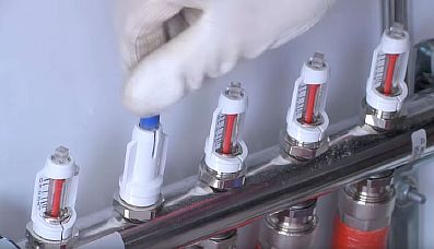
The service life and quality of the floor depends on how accurately the setting is made.
Mixing valves
Depending on the desired effect, there are various connection methods. Each of them without fail implies the installation of mixing valves. These devices are required to connect hot and cold water. The latter is supplied from the heating circuit, the first from the boiler. The system can be adjusted automatically or manually, which requires additional installation of the control servo. There are two types of mixing valves.
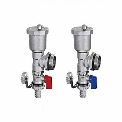
Two way servo
This servo is also called feed servo. Its main difference from conventional valves is the ability to conduct water in only one direction. If the valve is incorrectly reassembled, it begins to malfunction and quickly fails.
"Feeding" - conducts water only in one direction
A ball or a special rod is used as a shut-off part for it. Adjustment is made either by turning the ball or by moving the stem. To carry out these manipulations, electric drives are used.
The most popular way is a thermostatic head equipped with a water sensor, which regularly monitors the temperature of the heat carrier. Taking into account the received data, the head turns on or off the valve. So, from the return, the coolant is supplied regularly, and from the boiler only as needed.
The principle of operation of the device explains the main advantage of the manifold, which is equipped with a supply valve. The floors with this equipment do not overheat, which significantly increases their service life. The low flow capacity of the valve creates a smooth regulation of the coolant temperature, significant jumps in this case are excluded.
The supply valves are characterized by ease of installation and subsequent operation. They are quite often found in the scheme of self-made collectors for underfloor heating, but they have some limitations in their application. Two-way devices are not advised to be installed in systems that operate in rooms larger than 250 square meters.
Three-way systems
Three-way elements are arranged differently. This equipment integrates the operation of a bypass supply valve and a bypass valve. The valve consists of a body with one inlet and two outlets. For regulation, either a rotating ball or a special stem is used.
The peculiarity of this type of device is that the regulating part shuts off the flow completely, and distributes the incoming water, mixing it. The temperature is adjusted automatically, for this the valve has a drive system that receives signals from different sensors.
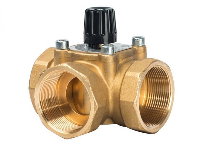
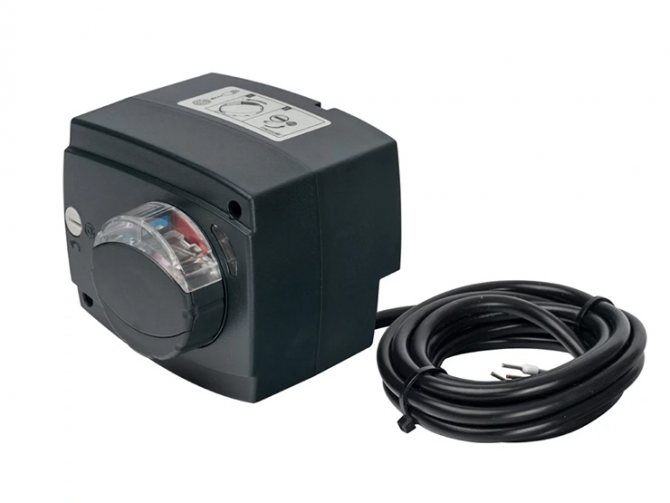
Such valves have servo drives
As a rule, 3-way valves are equipped with servo drives, which are controlled by thermostatic sensors or weather-compensated controllers.The servo drive activates the locking mechanism, which is set to the required position to obtain the required indicator of the heated coolant and return flow.
Weather-compensated controllers are required to adjust the system's power to the weather. For example, during a severe cold snap, the room will begin to cool down much faster, that is, it will be much more difficult for the heating system to do the job.
To facilitate the task, it is necessary to increase the costs of the heat carrier and increase the temperature. The main disadvantages of three-way elements include a significant throughput. Under these conditions, even a slight shift in regulation can lead to a sharp change in water temperature.
Three-way elements are used for collectors installed in rooms larger than 250 sq. m and systems with a large number of circuits. Moreover, they are used for structures that are equipped with weather-dependent sensors that determine the required floor temperature taking into account atmospheric conditions.
Can a collector be installed below the level of the warm floor - for example, in the basement?
There are times when the distribution and mixing unit has to be installed not on the floor of the warm floor, but below, for example, if the boiler room is in the basement, or you simply do not want to spoil the interior of the apartment.
Such a wiring is permissible, the installation of the collector is carried out in the same sequence as usual. There is only one problem - automatic bleeding of air masses from the line is not possible if the air vent is located on the comb.
Output - installation of an air vent on the return pipe between the comb and the floor hinges, and in front of it, a locking device with a shut-off valve is installed. Access to the air vent is mandatory.
For your information! Since an air vent is required for each branch of the floor, it is worth considering the advisability of installing the collector below the level of the warm floor.
Warm water floor refers to a modern heating system, perfect for furnishing in private houses. With proper installation of the "pie" of the floor and the collector, the structure is able to provide comfortable conditions in the room.
Device with 2-way supply valves
The two-valve manifold assembly has the following features:
Double Valve Manifold Kit
- cold and hot coolant mixes constantly. This prevents overheating of the device and prolongs its service life;
- the temperature changes are smooth, since the 2-way valves have a small flow capacity;
- are not used in small rooms, the area of which is less than 200 sq. m.
Advantages of using collectors in underfloor heating
Devices that are installed assembled with all additional elements provide the following benefits:
How to assemble a collector for a warm floor
- energy savings in comparison with traditional heating systems (on average by 30-50%);
- high safety due to the absence of open-type elements, which can become a source of a fire hazardous situation;
- the service life of the collector group is several tens of years. Only pipelines are subject to periodic replacement;
- the optimal parameters of the microclimate in the heated room are provided.