Purpose of pressure regulators
The devices are capable of performing a number of important functions simultaneously. The first is to prevent pressure build-up. Almost all household plumbing fixtures are capable of operating in a mode up to 3 atm. Exceeding this parameter is fraught with overloads for the water supply system at home. As a result, the service life of functional units on washing machines and dishwashers is noticeably reduced, and the reliability of connecting adapters and gaskets decreases.
Pressure regulators prevent water hammer. We are talking about sudden changes in water pressure arising from malfunctions of pumping equipment or improper use of valves. Water hammers can lead to very disastrous consequences, including pipeline ruptures and breakdowns of boiler units. Sometimes the pressure surges are so large that the boiler explodes.
Another useful feature is economical water consumption. By adjusting the water pressure, you can significantly reduce its consumption. For example, if the pressure is reduced from 6 to 3 atm, the savings can reach 20-25% (while opening the tap, a smaller jet will be released).
Hydraulic controllers help reduce noise when using mixers and taps. The reason for the annoying hum of the fittings lies in the increased pressure, due to which the water pressure after opening the valve acquires a boundary force. Thanks to the regulator, the water pressure becomes stable and decreases to optimal values.
In the event of a pipeline rupture, water losses will decrease, since the device reacts to a drop in pressure by reducing the water supply. Basically, water supply systems of private houses are equipped with regulators (reducers), where they, together with a hydraulic accumulator, are switched to a circulation pump.
Features of devices
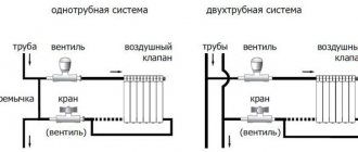
Water pressure regulators are presented in the plumbing market in several varieties. At the place of installation, the devices are divided into two groups:
- "To yourself." The flow voltage is stabilized in front of the reducer;
- "after myself". The water pressure is stabilized downstream of the installation point.
Regardless of the principle of operation, any pressure switch consists of the following structural elements:
- valve (piston). Serves as the core of the device;
- springs (membranes);
- housing. It can be cast iron, brass or steel.
In addition to the standard set of parts, some models are additionally equipped with a pressure gauge, a coarse filter, an air valve and a ball valve.
In terms of throughput, the regulators are divided into household (0.5-3 m3), commercial (3-15 m3) and industrial (over 15 m3).
Types of regulators
According to the principle of operation, RVD are piston, diaphragm, flow-through, automatic and electronic.
Reciprocating
The simplest design water pressure valves (also called mechanical). Pressure adjustment is carried out by a compact spring-loaded piston by reducing or increasing the bore. To adjust the outlet water pressure, the device has a special valve: by rotating it, you can loosen or compress the spring.
The weaknesses of piston regulators include their sensitivity to the presence of debris in the water: piston clogging is the main cause of damage. To prevent such phenomena, a special filter is usually included in the gearbox kit. Another disadvantage is the large number of movable mechanical assemblies, which affects the degree of reliability of the gearbox. The piston device is capable of regulating the pressure in the mode of 1-5 atm.
Membrane
Very reliable and unpretentious devices that make it possible to adjust the water pressure over a wide range (0.5-3 m3 / h). For living conditions, this is a very decent indicator.
The core of the device is a spring-loaded diaphragm: a self-contained sealed chamber is used for its installation to avoid clogging. The recoil from the compressing or expanding spring is transferred to a small valve, which is responsible for the size of the cross-section of the outlet channel. The cost of diaphragm restraints is quite high. Due to the complexity of replacement, this procedure is usually performed by experienced plumbers.
Flowing
A feature of this model of water pressure regulators is that there are no moving elements in it. This has a beneficial effect on the reliability and durability of the devices.
The pressure is reduced due to the intricacies of narrow channels. When passing through numerous turns, water is divided into separate branches, at the end again merging into one, but not so fast. In domestic applications, flow reducers can be found in irrigation systems. The disadvantage of the device is the need for an additional regulator at the output.
Automatic
Small unit consisting of a diaphragm and a pair of springs. Special nuts are used to change the compression force. When the inlet water has a weak head, this leads to a weakening of the membrane. The increase in pressure in the pipe provokes an increase in compression.
A spring forces the contacts on the automatic pressure reducer to open and close again. This, in turn, turns on and off the circulation pump of the forced water supply system. The design of automatic high pressure hoses basically duplicates membrane devices, differing only in the presence of two adjustment screws for setting the operating pressure range.
Electronic
A special mechanism monitors the water pressure in the pipe, for which a motion sensor is used. After processing the received data, a decision is made to turn on the pumping station. The electronic regulator will block the activation of the pump if the pipeline is not filled with water. The structure includes the main body, sensors, an electronic circuit board, a switching bushing (thanks to it, the supply wire is switched on) and threaded nipples for connecting to the system.
The stabilizer has a convenient display for displaying water flow characteristics. Mechanical regulators are sometimes not able to effectively protect the system from dry running, which is why it is necessary to constantly monitor it for the presence of water. In contrast, electronic models with a controller are able to constantly monitor the filling of water. Reducers of this type operate almost silently, reliably protecting all units from hydraulic shocks.
Customization and maintenance
Special standards for the operation of domestic water supply systems recommend the outlet water pressure in the range of 2-3.5 kg / cm2. This mode can only be obtained by adjusting the water pressure reducer. The speed of action of different models of RVD is different. The flow of the system provokes a decrease in the pressure force by about 1.5 atm (the exact indicator depends on the specifics of the circuit). After a few seconds, an increase in pressure is observed to a value below average. The ideal parameter of the output value should be inferior to the input value by at least 1.5 kg / cm2, otherwise this will lead to a noticeable deceleration of the speed of fluid movement through the pipes.
It is important to take these norms into account when adjusting water pressure reducers. To determine that the reducer is not working correctly, pair pressure gauges or a control fluid intake in front of the pressure regulator will help. It is possible to adjust the RVD only if the system is in working order and it has the required fluid pressure.Having created such conditions, in the course of rotation of the adjusting screws, you can easily determine all the changes in indicators that occur (this will be displayed on the pressure gauge). It is not recommended to carry out such manipulations without a measuring device, as this can lead to a violation of the factory settings.
During the operation of the high pressure hose, it is necessary to control the pressure in the system. If the output parameters of the device cannot be adjusted, the diaphragm is most likely damaged. Sometimes water starts to seep through the joints on the case. Any signs of breakage serve as a signal to dismantle and disassemble the device. Most often, the membrane is injured by a rusty spring or stem. These assemblies, along with seals, can be found in repair kits available from your plumbing store.
When installing a modern heating system, you cannot do without shut-off and control valves. The taps are installed in the places of boiler piping, water drainage, air bleeding, bypass installation, circulation pump, heating radiators, etc. They are designed to regulate water flows and shut off in case of breakdown or replacement of some devices or elements in the heating system. Even the most balanced, perfect and reliable home heating scheme requires at least one tap installation - to drain the coolant. In reality, there should be much more locking elements. And what functional responsibilities each tap will have depends on its location in the heating system; structurally, they can also differ from one another.
The main types of valves for the heating system
The basic principle of any faucet is to shut off and regulate the flow of fluid. This can be done with the help of several types of mechanisms that were used in the construction of cranes and gave them names. Each type of locking and adjusting device has its own advantages and disadvantages, which make it possible to better match them to a specific place in the heating system.
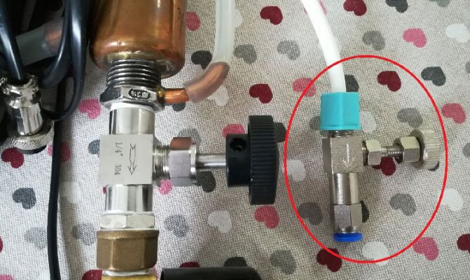
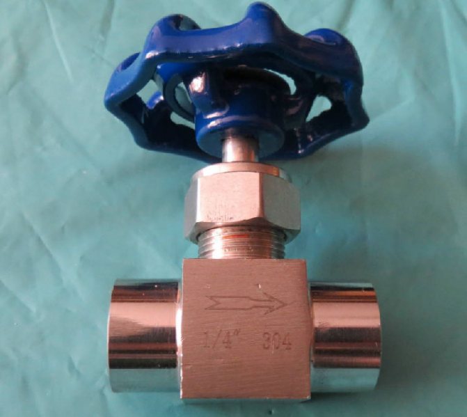
Important! Many valves are marked with an arrow on the body, which indicates the direction of fluid movement. Incorrect connection to the pointer can lead to breakage or malfunction of the locking device.
Each tap, even fully open, is an additional resistance in the path of the water flow, which reduces the head and pressure of the coolant, and also requires an increase in the power of the circulation pump.
The most popular types of valves for the heating system by design and purpose:
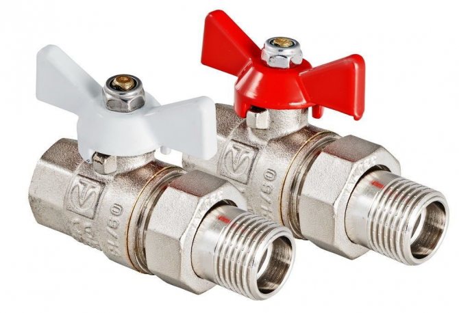
Ball - the name determines the type of construction. Inside there is a ball with a hole that can be rotated 90 °. This universal valve is used in those places where it is necessary to shut off the flow of liquid or gas in one motion. The features of this device are simplicity of design, low resistance to water flow, fast closing, not intended for adjustment. The shut-off ball is rotated using a butterfly valve or a lever;
What ball valves can you regulate the flow
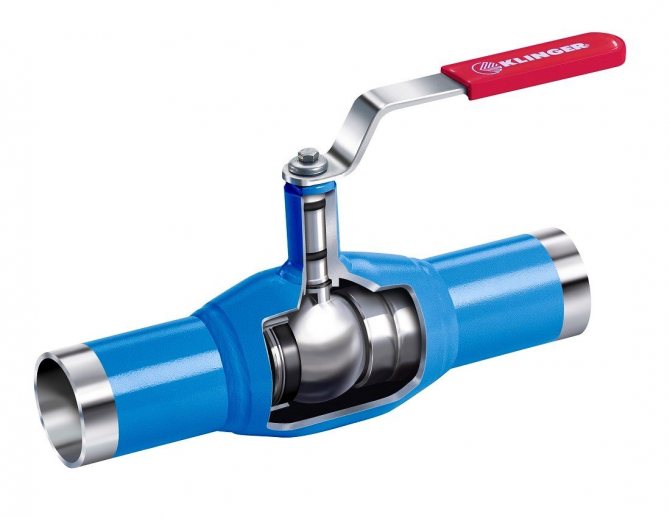
Some companies produce ball valves with which you can regulate the water supply, but they are rarely used in homes, since they have a large capacity, some design features and a rather high price.
The design of such cranes is mainly welded, that is, the entire mechanism is located in the pipe and is equipped with a valve.
The peculiarity of such valves is in their wear-resistant O-rings. The service life of these rings is significantly longer, although the water flow will wear them out too. Usually, positions are indicated next to the control valve in which the shut-off mechanism can be opened.
There are ball valves where O-rings are not used at all. Such designs are mainly applicable in industries and waterways, where the main position of the crane will almost always be in the open position.Liquids with temperatures ranging from -30 to +200 degrees can be delivered via such lines.
Features of "American" cranes
The scheme of connecting pipes using a threaded fitting, a gasket and a union nut, which received the slang name "American", in many issues of connecting shut-off valves is better than using a squeegee with a number of additional components (threads, couplings, locknuts and counter threads). Also, with the old method of connection, very often it was necessary to rotate a pipe or a crane. This problem is not present now. The "American" is especially effective during the installation or replacement of radiators, heated towel rails, meters, expansion tanks and other units of the heating system. And you cannot do without it in hard-to-reach, inconvenient places where it is impossible to make a welding connection. To replace, dismantle or install any device included in the heating system, just turn the handle or valve to the “closed” position to shut off the coolant flow, and you can unscrew the union nut with a wrench, freeing any unit. From all of the above, we can conclude that the "American" is not so much a crane as a diagram of the connection of pipe parts and elements. This scheme can be used in any kind of shut-off valves, but most often the "American" is connected to a ball structure. Also, you can often find an American woman with a three-way valve equipped with a valve and equipped with an electric drive.
Important! There is an angular version of the "American", which has the same principle of action as the usual - straight.
Features of thermocontrol valves
The principle of operation of mechanical, electronic and electric thermostats is the same. They operate a valve that regulates the flow of the heating medium through the radiator. Thermal sensors of electronic taps are placed far outside the body, and measure the air temperature in those places in the room that are of interest to the consumer. In this way, they are better than mechanical and electrical ones, which determine the ambient temperature in the immediate vicinity of the heater. Also, the electronic system allows the temperature to be controlled remotely using a server.
In each system, consisting of pipes connected in series, there are sections where it is periodically necessary to shut off the flow of the working medium. For this, different types of shut-off and control valves are used. In high pressure systems, a needle valve is used as this mechanism.
Application area
Needle valves are not as popular as ball and balancing valves and should not be confused.
Main areas of application:
- Placement on auxiliary pipelines with a pressure of up to 10 MPa (with the exception of high pressure taps) to control the flow of liquid, steam, gases. The tapered plug head is more reliable than the straight seats of conventional valves. This prevents the O-rings from scuffing.
- High pressure pipelines. Needle rods allow flow control without interruption to the system.
- For connecting pressure gauges;
- In cooling water injection systems;
- In heating for air release;
- In carburetors of cars and motor vehicles (in the form of a needle valve);
- For home brewing. Here, needle valves are used to control the rate of exit of the product from the selection of the membrane (or any other) reflux condenser from the distillation still into the cooling system.
Purpose and application
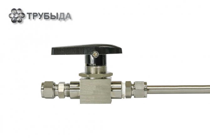
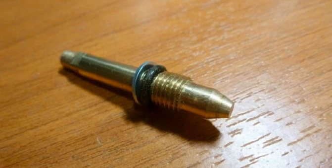
The needle valve is part of the shut-off and control valves. Such valves are installed on pipelines with a liquid, viscous or gaseous internal medium. They are distinguished from other types of valves by the structure of the lower part of the stem, which directly blocks the lumen.A needle valve has a stem that is tapered downward to make it look like a needle.
The valve consists of the following parts:
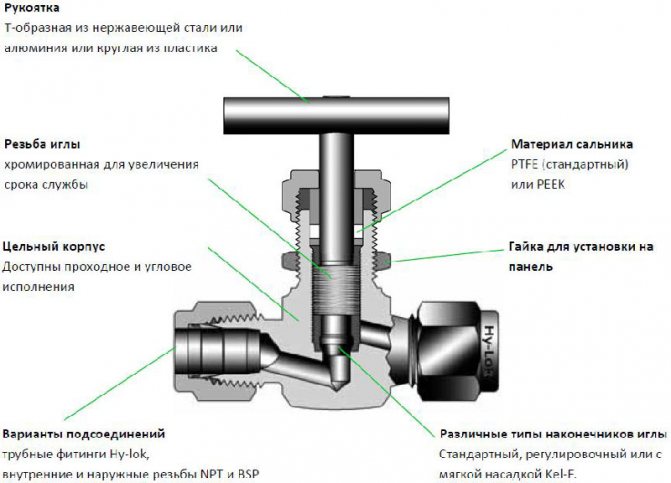
The principle of operation of the needle valve is simple: when the handle is rotated clockwise, the stem with the spindle is set in motion, while the spindle is screwed into the thread of the body and blocks the lumen. When rotating in the opposite direction, the stem rises and the gap is cleared. Such parts are installed on pipelines of both small and large diameters.
It is interesting! A distinctive feature of the needle valve is the structure of its spindle, which tapers conically downward. Its lower part is sharp and resembles a needle. Another feature of this mechanism is the ability to withstand significant pressure from the working environment.
The needle valve is used in systems for any purpose. It is irreplaceable in two cases.
- The first is to regulate the flow upstream of the pressure gauge. A pressure gauge is a device designed to measure the pressure in a system. It needs periodic maintenance. In addition, sometimes pressure gauges fail and lead to depressurization of the system. A needle valve is installed in front of the pressure gauge, which smoothly shuts off the flow if necessary. This ensures tightness in the system, even if the pressure gauge is faulty or during maintenance.
- The second case when a needle valve is irreplaceable is pipelines with high internal pressure. This device is capable of withstanding high pressure. Some types of needle valves are designed to operate at pressures up to 40 MPa. The device allows you to smoothly shut off the flow, preventing large pressure fluctuations in the system.
Device and principle of operation
A needle valve structurally consists of the following parts:
- cast body;
- stem with a cone-shaped tip;
- a handle fixed to the rod with a nut;
- screw cap on the body;
- seals;
- adjustment screw.
Design and principle of operation: when the handle is turned counterclockwise, the stem is displaced along its axis along the thread cut inside the body, upward, opening the through hole. In reverse rotation, the flow is blocked. Due to the conical end of the stem, a large contact area with the seat is provided, the flow is smoothly and precisely regulated.
The main difference between a needle valve and other types of shut-off valves is withstanding high pressure, ease of adjustment, and no reverse flow.
Inside the zigzag channel, inside the body, there is a saddle, into which the end piece of the stem enters when the spindle is turned clockwise. A needle faucet can have not only a hard tip, but also a soft one.
To increase the service life of the stem thread, a special chrome coating is applied to its surface.
The crane can be operated manually or mechanically. To automate control, it is enough to connect the stem to the electric drive.
Types of needle valves
Valves of this type differ in several parameters. By design, there are three types of devices:
Shut-off valves are capable of completely shutting off the flow. They are the most resistant to high pressure and temperature, but their service life is short. These valves often contain liquids and gases, which can corrode the metal. Shut-off valves are used on large highways.
Regulating needle valves are used when it is necessary to change the properties of the internal working environment.For example, reduce pressure or volume. The area of their application is pipelines of small diameter with a liquid medium.
Balancing valves are designed to regulate hydraulic resistance. In other words, they redirect the flow of fluids from one pipe to another, keeping the balance of volume, pressure, velocity or temperature at a given level. They are often installed on heating systems.
By design features, valves are distinguished:
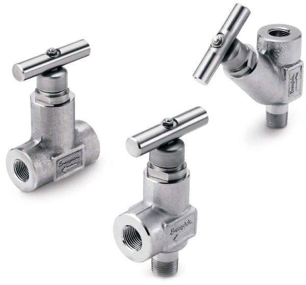
Straight-through valves are installed on pipelines in places where pipes are directly connected. They are relatively large compared to the pipe size. Due to the design features, stagnation often occurs in such mechanisms, they must be periodically cleaned.
Angle valves are used where pipes are at an angle to each other. For example, if the pipeline turns to form an elbow. An angle-type needle valve is installed at the turning point. They come in different diameters and are designed for systems with any interior environment.
Direct-flow structures are distinguished by their relatively large length and weight. In everyday life, they have not found widespread use, despite a number of advantages, including the less possibility of stagnation inside the mechanism. They are used as control valves in oil pipelines.
By the method of ensuring the tightness of the system:
One of the elements of the stuffing box valve is a seal, which prevents the working medium from escaping to the outside, regardless of the position of the stem. This option is not always reliable from the point of view of tightness.
Bellows valves use vacuum as the sealing medium. Vacuum spacers are often used in high pressure systems. They are more reliable and less likely to leak.
General information about the nomenclature.
According to GOST R 52720-2007. “Pipe fittings. Terms and definitions ", clause 4.3, a valve is" a type of valve in which a locking or regulating element, which has the shape of a body of revolution or its part, rotates around its own axis, arbitrarily located in relation to the direction of flow of the working medium. A ball valve according to clause 5.49 in GOST R 52720-2007 is "a valve, the locking or regulating element of which has a spherical shape." The ball valves presented in this section can be divided into two types based on the principle of shut-off.
The first type, floating ball valves, is the most common in the world. The method of shutting off the flow for this type of valves is as follows - the flow presses on the ball in the closed position and due to the pressure difference between the inlet and outlet, the ball is pressed against the O-ring located on the outlet side, ensuring a tight shutoff of the pipeline. Accordingly, the greater the pressure drop, the greater the force with which the ball is pressed against the seat. In this case, the seal located on the side of higher pressure does not ensure tightness and allows the flow to penetrate into the cavity between the seal, the ball and the ball valve body. In the absence of a pressure drop between the inlet and outlet, the tightness is ensured by the tight fit of the seals to the ball. The tightness of the stem, with the help of which the ball rotates, can be ensured by various types of seals, depending on pressure, chemical compatibility with the controlled medium, temperature, etc. Ball valves of this type make it possible to shut off the flow of product moving in two directions.
The second type is trunnion ball valves, also called TRUNION ball valves. In these products, the ball is not displaced relative to the axis of rotation, and the tightness is ensured by forced pressing of the spring-loaded seals to the surface of the ball due to the pressure of the controlled medium.Ball valves of this type allow you to shut off the flow in either one or two directions, depending on how many spring-loaded saddle seals are included in the ball valve. Such ball valves are manufactured with nominal diameters ranging from 50 millimeters and up to values exceeding 1000 mm, they can operate in high pressure drops over a wide temperature range. A large number of options are also available for them, such as leak control, nozzles for injection of sealant, etc. As a rule, such products are made individually, taking into account all the requirements of the Customer and various nuances of flow characteristics, such as speed, pressure, temperature, etc.
In terms of functionality, ball valves can be divided into shut-off, control and distribution-mixing. According to GOST R 52720-2007, shut-off valves are valves designed to shut off the flow of the working medium with a certain tightness ", control valves are" valves designed to regulate the parameters of the working medium by changing the flow rate ", and distribution and mixing valves are" valves designed for distribution flow of the working medium in certain directions or for mixing flows. "
Shut-off ball ball valves operate according to the 2/2 scheme and are designed to completely open and close the flow. It is not recommended to leave such ball valves in an intermediate position, as this can lead to erosion of the ball seal and rapid failure of the ball valve.
Distribution and mixing ball valves presented in the nomenclature of our company operate according to the 3/2 scheme and differ in the shape of the channel inside the ball - T-shaped or L-shaped. Designed for both flow switching and mixing (only ball valves with a T-channel in the ball). When selecting three-way ball valves, special attention should be paid not only to the flow distribution scheme, but also to the flow direction, since not all models can work in two directions.
Control ball valves are designed to accurately control the flow of liquids and gases passing through the valve. Such devices are specially designed to be able to continuously operate in the intermediate position of the ball. They use special seals that are resistant to erosion. Regulating ball valves are available in two types in our range - V-notch ball (standard products) and ball valves with regulating grate. The latter are used for difficult media with high pressure and flow rate, as well as for pipeline diameters above 50 mm and are calculated individually for the specific needs of the customer.
Advantages and disadvantages
Despite the large number of varieties, all needle valves have common positive and negative characteristics.
Note! Needle valves are always made of metal, sometimes they have a plastic handle. The valves are capable of withstanding temperature conditions from -20 to + 200 ° С. Depending on the type of valve, the maximum pressure at which they can operate reaches 15 to 45 MPa.
The advantages of needle valves include:
- the ability to withstand large temperature drops;
- the ability to function under conditions of increased pressure;
- simplicity of design, the possibility of self-installation and maintenance;
- resistance to corrosion with the appropriate quality of metal parts;
- durability - the service life reaches 15 years;
- smooth flow shutoff, which is important for high pressure systems, where a sharp shutdown can provoke a breakthrough;
- the tightness of the device in relation to the external and internal environments with the complete lowering of the stem;
- work with a viscous internal environment in a free-flow pipeline.
The disadvantages of needle taps include:
- high hydraulic resistance, which leads to hydraulic losses of kinetic energy, in other words, it is more difficult for a working medium to pass through a section with a needle valve than through a smooth pipe;
- inability to work with a viscous internal medium under high pressure conditions;
- a relatively large section of pipe replacement (a large indicator of the face-to-face length), which affects the physical properties of the working environment;
- the need for periodic cleaning of some types of products from liquids that get inside;
- work only with one-way flow, impossibility to redirect the flow in the other direction;
- the difficulty of replacing the valve when it fails, since this part is non-removable.
Types of needle valves for high pressure heating. Click!
A needle valve, or, in other words, a valve, is a reinforcement structure that is installed on a pipeline and used to supply gas and various liquids, including water.
This article will consider the advantages and disadvantages of this device, its varieties, the principle of operation, the purpose of the needle crane.
Benefits
The needle valve has several advantages:
- The device is characterized by smooth gas regulation for a certain liquid.
- The material from which the needle faucet is made does not lend itself to rusting (anti-corrosion material), due to which the structure will last a long time.
- According to the second point, the needle valve has a long service life (the period of operation is 12 years).
- The needle valve can be disassembled to replace obsolete parts.
- Has great pressure resistance. The valve is capable of withstanding a pressure of 230 bar.
- Resistance to the temperature of the medium flow (from -25 degrees Celsius to 210 degrees Celsius).
- The needle valve has a simple design and is easy to use in a variety of applications (most often in industry).
- It is possible to repair a small breakage of the needle valve.
disadvantages
If there are advantages, then there are disadvantages:
- The needle valve cannot be installed on the section of the pipeline where the dirty water is supplied.
- The installation takes up a huge area.
- If the needle valve is severely damaged, the device cannot be restored. Therefore, in this case, it is not worth saving, since soon the structure will become unusable.
There are many more advantages than disadvantages, therefore, the needle valve is widely used in various fields.
A needle faucet is made from different materials: cast iron (if the pipeline flow is water), and stainless materials (bronze, nickel, brass and other stainless metals) - they are used in an industrial environment. And where there is a huge load, a steel needle crane is used.
Views
Cranes are divided into several types:
- Shut-off. This type can withstand high pressure and temperature. Has ease of assembly of parts. Mainly used in industrial environments. The downside is the accumulation of liquid residues, which leads to material corrosion.
- Regulating needle valve. Has a diameter of 20 mm. The material of this type is steel. It is installed on pipeline sections where the medium is water, steam or liquids that contain oil.
- Balancing needle valve. Has little resistance. The material of this type is brass. The flow in the pipeline is water.
- Straight through needle valve. This type of crane has its own parameters: the diameter starts from 6 mm and ends with 25 mm, the body consists of steel material, it is installed for liquid and gaseous media. The temperature can withstand up to 310 degrees Celsius. The weight of the straight-through crane reaches half a kilogram.
- Corner needle faucet. This type is most often used to supply water from a pipeline. It can withstand pressures up to 300 bar and temperatures up to 630 degrees Celsius. The corner faucet reaches a diameter of 8 mm.The material of this type of needle valve is also steel (there may be others).
- Direct flow needle valve. It is mainly used in the oil industry. The material of this type is steel. Installed on pipelines that are designed for the processing of petroleum products. If necessary, the straight-through valve can simply be replaced with another.
- Poppet valve. This type is used to supply gaseous mixtures.
- Stuffing box needle valve. The temperature can withstand up to 60 degrees Celsius, and the pressure up to 340 bar. This look is made of steel material. The stuffing box valve can be found in the chemical industry.
- Bellows or, in other words, vacuum needle valve. Replacement of parts of this type is impossible, because this structure cannot be disassembled.
The vacuum valve has a tightness and reliability that is distinctive from all others. Made of stainless steel metal. It has a long service life (about 15 years).
The bellows needle valve is subdivided into several types. Resistant to temperatures up to 350 degrees Celsius.
These are the main types of needle faucet, which have their own distinctive features. Each needle valve has its own thread.
Note: the valve must be installed in the place where the manometer is connected and disconnected (measuring the pressure of the medium in the pipeline installation).
The valve is self-controlled for self-regulation of the medium flow. The needle valve also has two functions: distillation and rectification. Rectification is a procedure for separating various mixtures of vapor and liquid using heat exchange (evaporation, condensation). Distillation is the evaporation of a certain liquid and the condensation of steam.
The smallest selection is one drop in 6.5 seconds. This construction is used for the selection of alcohol, that is, it is a rectified alcohol. It can be homemade.
The best is the Camozzi needle tap.
It is used in water supply or heating, because this device smoothly stops the liquid, so that unpleasant situations can be avoided. The needle valve is used because of its long service life.
Principle of operation
Needle valve device. (Click to enlarge)
The composition of the needle valve: body (different material), spindle, valve and cover are the four components of the structure.
The needle valve can be operated in two ways: manually and using motorized control.
With the help of the actuator, the shutter is set in motion, after which the valve opens and closes. Most needle valves have fine and precise adjustment of the regulation of any medium.
Its useful to note: it is important to choose a needle faucet that is right for your environment.
Needle valves are needed in order to set up the reliable operation of the pipelines. They will help you avoid dangerous and unpleasant situations. Before buying, be sure to familiarize yourself with all the parameters of the device.
Watch a video in which a specialist explains the advantages of a Camozzi needle crane with a specific example:
What to consider when choosing a device?
Before purchasing a needle valve, it is necessary to determine on which section of the pipe it will be located, what is its diameter and the physical characteristics of the internal environment... The size of the valve must correspond to the diameter of the pipe, it is desirable that they are made of materials of the same name.
In addition, an important characteristic to consider is the pressure under which the liquid or gas moves through the pipe. At pressures up to 15 MPa, any needle valves can be installed. In the event that the pressure of the working medium exceeds this indicator, only two types of needle valves can be used. They are produced under the markings VI and VT-5. These types can withstand pressures up to 45 MPa.
The direction of the valve must be indicated, allowing you to determine which part of it is in contact with the leading section of the pipe, and which with the outlet. When properly installed, the valve shuts off the flow during clockwise rotation of the handle, and opens counterclockwise.
All parts of the device must be intact. Sites of minor scratches, coating chips or cracks in the future may cause a reduction in service life.
When purchasing a valve, you should check how the handles rotate, how the stem and spindle behave. Rotation should be carried out with little resistance, the stem only move up and down. There should be no extraneous movements to the sides. In a working mechanism, when the spindle reaches the maximum lowering, the handle does not scroll.
Control methods
8.1 Control of conformity of geometric dimensions (4.3, 5.2.6) is carried out using universal or special measuring instruments. The threads are checked with thread gauges.
The appearance of the valves (5.2.3), completeness and markings are checked visually.
8.2 Testing of valves for tightness is carried out on a stand with water pressure of 1.5 MPa (15 kgf / cm2).
The stand should be equipped with devices that provide water supply with a pressure of at least 1.5 MPa (15 kgf / cm2), shut-off valves, indicating pressure gauges.
The tests are carried out at steady-state pressure during the time required for the valve inspection, but not less than 30 s.
Water is supplied to one of the coupling ends with the other end plugged. The position of the shutter must ensure the flow of water into the internal cavities of the valve.
Water skipping is not allowed. Visual control.
8.3 Passage of water through a closed control device (4.4) is checked at an excess water pressure of 1 kPa (0.01 kgf / cm2) using a measuring container and a stopwatch.
8.4 Pressure measurement error during testing shall not exceed + 2.5% of the measured value.
8.5 Checking the regulating device for changing the thermal power (5.2.5) of heating devices is carried out in three positions: the regulating device of the valve is open by 1/4, 1/2, by 3/4 and a fully open valve installed on the stand at a pressure of up to 1, 0 MPa. The turning should be smooth, without jamming. The flow rate of the coolant through the tap is determined using a measuring container and a stopwatch, and it should be proportional to the indicated values from the flow rate with the tap fully open.
8.6 The magnitude of the torque (5.2.2) is checked using a dynamometer or a special device that ensures the creation of a given value of the torque.
8.7 The service life (5.2.7) is determined on a test bench (8.2). If there is a stuffing box seal in the valves, it is allowed to tighten them in the process of determining the technical resource and is not allowed when determining the MTBF.
8.8 A list of equipment and measuring instruments required for product control is given in Appendix A.