The design and thermal calculation of a heating system is an obligatory stage in the arrangement of heating a house. The main task of computing activities is to determine the optimal parameters of the boiler and the radiator system.
You must admit that at first glance it may seem that only an engineer can do a heat engineering calculation. However, not everything is so complicated. Knowing the algorithm of actions, it will turn out to independently perform the necessary calculations.
The article describes in detail the calculation procedure and provides all the necessary formulas. For a better understanding, we have prepared an example of thermal calculation for a private house.
Norms of temperature regimes of premises
Before carrying out any calculations of the parameters of the system, it is necessary, at a minimum, to know the order of the expected results, as well as to have available standardized characteristics of some tabular values that must be substituted in the formulas or be guided by them.
Having performed calculations of parameters with such constants, one can be sure of the reliability of the sought dynamic or constant parameter of the system.

For premises for various purposes, there are reference standards for the temperature regimes of residential and non-residential premises. These norms are enshrined in the so-called GOSTs.
For a heating system, one of these global parameters is the room temperature, which must be constant regardless of the season and ambient conditions.
According to the regulation of sanitary standards and rules, there are differences in temperature relative to the summer and winter seasons. The air conditioning system is responsible for the temperature regime of the room in the summer season, the principle of its calculation is described in detail in this article.
But the room temperature in winter is provided by the heating system. Therefore, we are interested in the temperature ranges and their tolerances for the deviations for the winter season.
Most regulatory documents stipulate the following temperature ranges that allow a person to be comfortable in a room.
For non-residential office premises with an area of up to 100 m2:
- 22-24 ° C - optimal air temperature;
- 1 ° C - permissible fluctuation.
For office-type premises with an area of more than 100 m2, the temperature is 21-23 ° C. For non-residential premises of an industrial type, the temperature ranges differ greatly depending on the purpose of the premises and the established labor protection standards.

Each person has their own comfortable room temperature. Someone likes it to be very warm in the room, someone is comfortable when the room is cool - this is all quite individual
As for residential premises: apartments, private houses, estates, etc., there are certain temperature ranges that can be adjusted depending on the wishes of the residents.
And yet, for specific premises of an apartment and a house, we have:
- 20-22 ° C - living room, including children's room, tolerance ± 2 ° С -
- 19-21 ° C - kitchen, toilet, tolerance ± 2 ° С;
- 24-26 ° C - bathroom, shower, swimming pool, tolerance ± 1 ° С;
- 16-18 ° C - corridors, hallways, staircases, storerooms, tolerance + 3 ° С
It is important to note that there are several more basic parameters that affect the temperature in the room and which you need to focus on when calculating the heating system: humidity (40-60%), the concentration of oxygen and carbon dioxide in the air (250: 1), the speed of movement of air mass (0.13-0.25 m / s), etc.
Heat transfer mechanisms in the calculation of heat exchangers
Heat transfer is carried out through three main types of heat transfer. These are convection, heat conduction and radiation.
In heat exchange processes that proceed according to the principles of the mechanism of heat conduction, heat transfer occurs as a transfer of the energy of elastic vibrations of molecules and atoms. This energy is transferred from one atom to another in the direction of decreasing.
When calculating the parameters of heat transfer according to the principle of thermal conductivity, Fourier's law is used:
To calculate the amount of heat, data on the time of passage of the flow, surface area, temperature gradient, and also on the coefficient of thermal conductivity are used. The temperature gradient is understood as its change in the direction of heat transfer per one unit of length.
The coefficient of thermal conductivity is understood as the rate of heat transfer, that is, the amount of heat that passes through one unit of surface per unit of time.
Any thermal calculations take into account that metals have the highest thermal conductivity coefficient. Various solids have a much lower ratio. And for liquids, this figure is, as a rule, lower than that of any of the solids.
When calculating heat exchangers, where heat transfer from one medium to another goes through the wall, the Fourier equation is also used to obtain data on the amount of heat transferred. It is calculated as the amount of heat that passes through a plane with an infinitesimal thickness:.
If we integrate the indicators of temperature changes along the wall thickness, we get
Based on this, it turns out that the temperature inside the wall falls according to the law of a straight line.
Convection heat transfer mechanism: calculations
Another heat transfer mechanism is convection. This is the transfer of heat by volumes of the medium through their mutual movement. In this case, the transfer of heat from the medium to the wall and vice versa, from the wall to the working medium is called heat transfer. To determine the amount of heat that is transferred, Newton's law is used
In this formula, a is the heat transfer coefficient. With turbulent movement of the working medium, this coefficient depends on many additional quantities:
- physical parameters of the fluid, in particular heat capacity, thermal conductivity, density, viscosity;
- the conditions for washing the heat-transfer surface with gas or liquid, in particular the speed of the fluid, its direction;
- spatial conditions that limit the flow (length, diameter, surface shape, its roughness).
Consequently, the heat transfer coefficient is a function of many quantities, which is shown in the formula
The dimensional analysis method allows one to derive a functional relationship between similarity criteria that characterize heat transfer with a turbulent flow in smooth, straight and long pipes.
This is calculated using the formula.
Heat transfer coefficient in the calculation of heat exchangers
In chemical technology, there are often cases of exchange of thermal energy between two fluids through a dividing wall. The heat exchange process goes through three stages. The heat flux for a steady-state process remains unchanged.
The calculation of the heat flux passing from the first working medium to the wall, then through the wall of the heat transfer surface and then from the wall to the second working medium is carried out.
Accordingly, three formulas are used for calculations:
As a result of the joint solution of the equations, we obtain
The quantity
and there is the heat transfer coefficient.
Calculation of the average temperature difference
When the required amount of heat has been determined using the heat balance, it is necessary to calculate the heat exchange surface (F).
When calculating the required heat exchange surface, the same equation is used as in previous calculations:
In most cases, the temperature of the working media will change during the course of heat exchange processes. This means that the temperature difference will change along the heat exchange surface. Therefore, the average temperature difference is calculated.And due to the fact that the temperature change is not linear, the logarithmic difference is calculated. In contrast to a straight-through flow, with a counter-flow of working media, the required area of the heat exchange surface should be less. If both direct flow and countercurrent flows are used in the same heat exchanger stroke, the temperature difference is determined based on the ratio.
Calculation of heat loss in the house
According to the second law of thermodynamics (school physics), there is no spontaneous transfer of energy from less heated to more heated mini- or macro-objects. A special case of this law is the “striving” to create a temperature equilibrium between two thermodynamic systems.
For example, the first system is an environment with a temperature of -20 ° C, the second system is a building with an internal temperature of + 20 ° C. According to the above law, these two systems will strive to balance through the exchange of energy. This will happen with the help of heat losses from the second system and cooling in the first one.
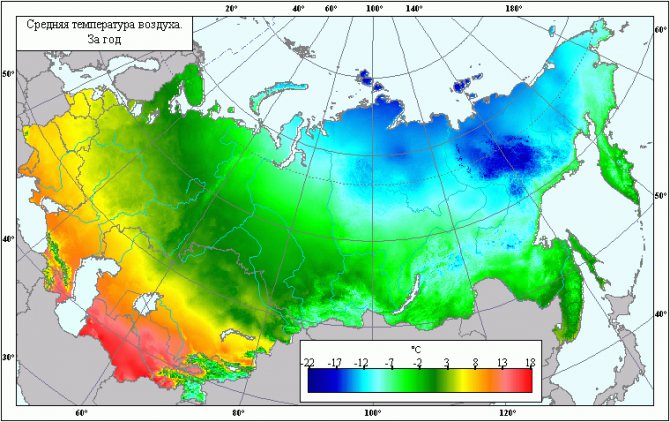
It can be said unambiguously that the ambient temperature depends on the latitude at which the private house is located. And the temperature difference affects the amount of heat leaks from the building (+)
Heat loss means the involuntary release of heat (energy) from some object (house, apartment). For an ordinary apartment, this process is not so "noticeable" in comparison with a private house, since the apartment is located inside the building and is "adjacent" to other apartments.
In a private house, heat “escapes” to one degree or another through the outer walls, floor, roof, windows and doors.
Knowing the amount of heat loss for the most unfavorable weather conditions and the characteristics of these conditions, it is possible to calculate with high accuracy the power of the heating system.
So, the volume of heat leaks from the building is calculated using the following formula:
Q = Qfloor + Qwall + Qwindow + Qroof + Qdoor +… + Qiwhere
Qi - the volume of heat loss from the uniform appearance of the building envelope.
Each component of the formula is calculated by the formula:
Q = S * ∆T / Rwhere
- Q - thermal leaks, V;
- S - area of a specific type of structure, sq. m;
- ∆T - temperature difference between ambient and indoor air, ° C;
- R - thermal resistance of a certain type of structure, m2 * ° C / W.
The very value of thermal resistance for actually existing materials is recommended to be taken from auxiliary tables.
In addition, thermal resistance can be obtained using the following ratio:
R = d / kwhere
- R - thermal resistance, (m2 * K) / W;
- k - coefficient of thermal conductivity of the material, W / (m2 * K);
- d Is the thickness of this material, m.
In older houses with a damp roof structure, heat leakage occurs through the top of the building, namely through the roof and attic. Carrying out measures for warming the ceiling or thermal insulation of the attic roof solve this problem.
If you insulate the attic space and the roof, then the total heat loss from the house can be significantly reduced.
There are several other types of heat loss in the house through cracks in structures, a ventilation system, a kitchen hood, opening windows and doors. But it makes no sense to take into account their volume, since they make up no more than 5% of the total number of main heat leaks.
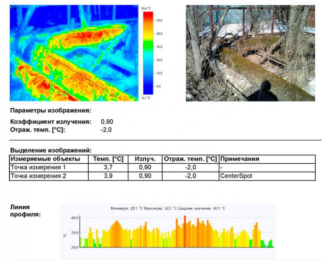
Thermal imaging inspection of the heating network
The calculation of heat losses in heating networks was supplemented with a thermal imaging survey.
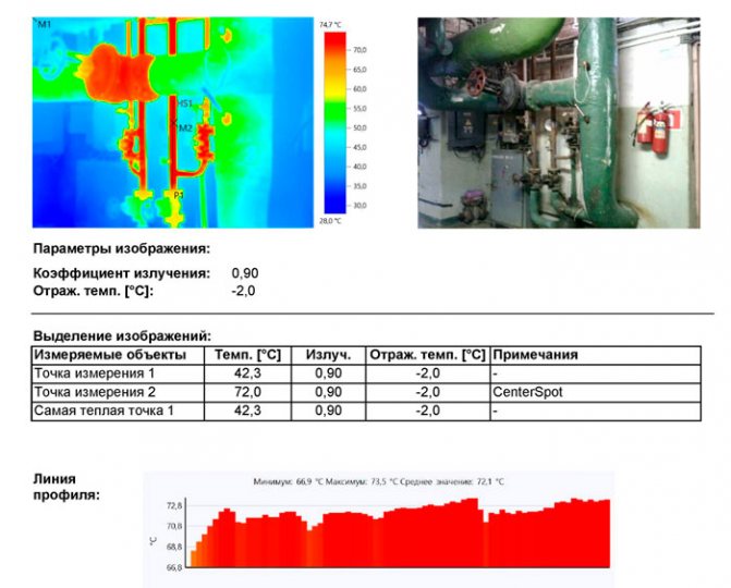
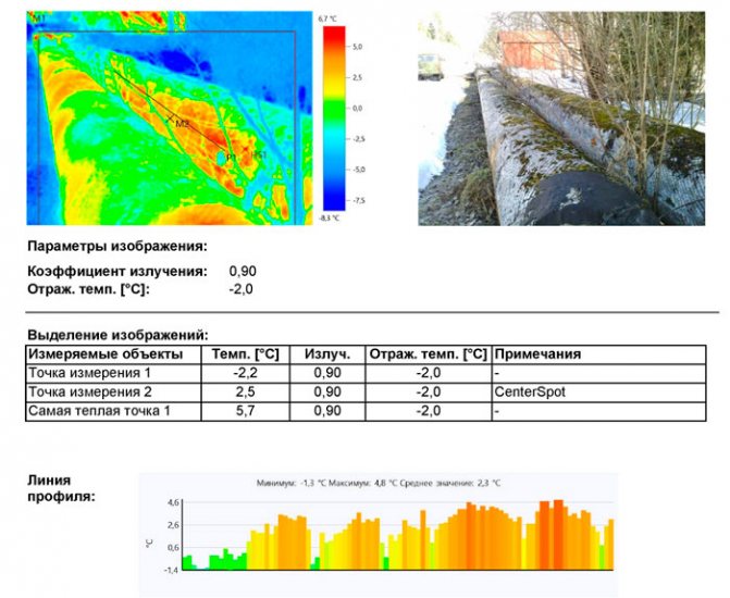
Thermal imaging inspection of the heating network helps to detect local defects in pipelines and thermal insulation for subsequent repair or replacement.
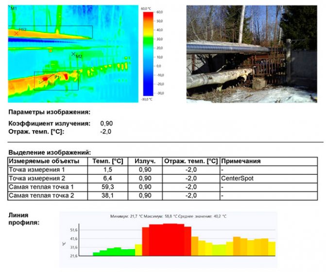
Thermal insulation of pipelines with heat carrier is damaged. The maximum temperature in open areas was 59.3 ° C
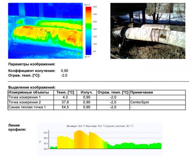
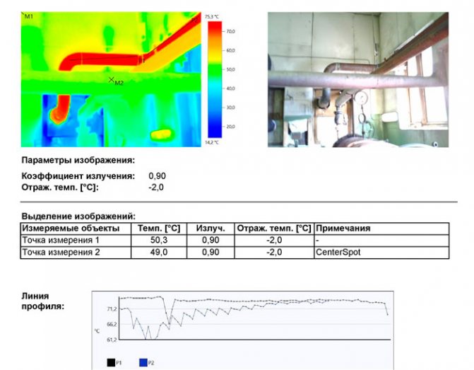
Partial destruction of thermal insulation of pipelines with a coolant. The maximum temperature in open areas was 54.5 ° C
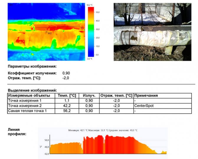
Partial destruction of thermal insulation of pipelines with a coolant. The maximum temperature in open areas was 56.2 ° C
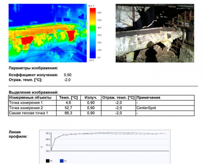
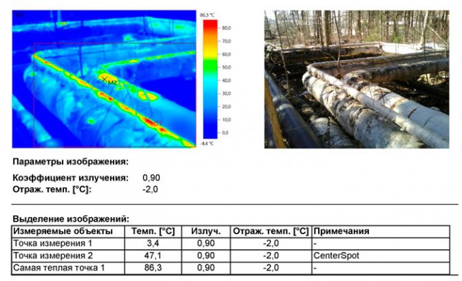
Thermal insulation of pipelines with heat carrier is damaged.The maximum temperature in open areas was 66.3 ° C
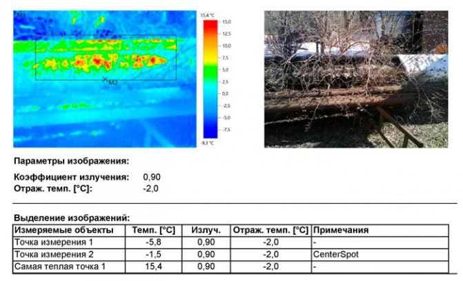
Open sections of pipelines without insulation.
Open sections of pipelines without insulation.
Partial destruction of thermal insulation of pipelines with a coolant.
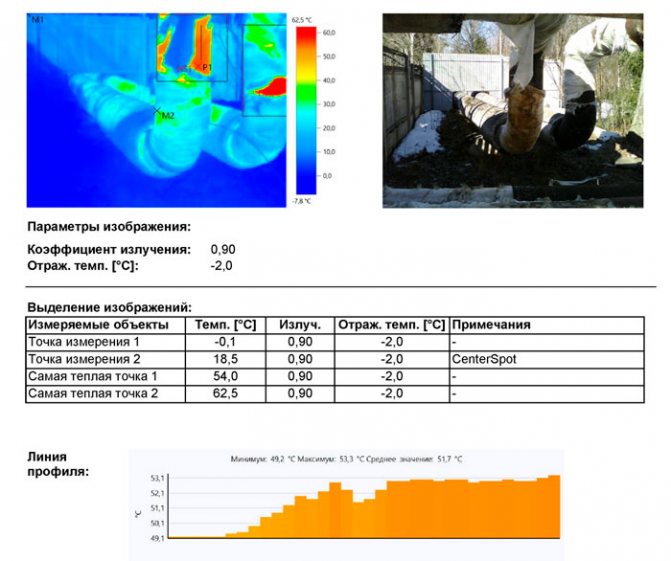
Partial destruction of thermal insulation of pipelines with a coolant. The maximum temperature in open areas was 62.5 ° C
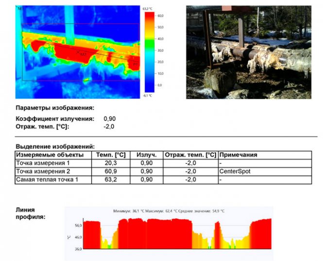
Partial destruction of thermal insulation of pipelines with a coolant. The maximum temperature in open areas was 63.2 ° C
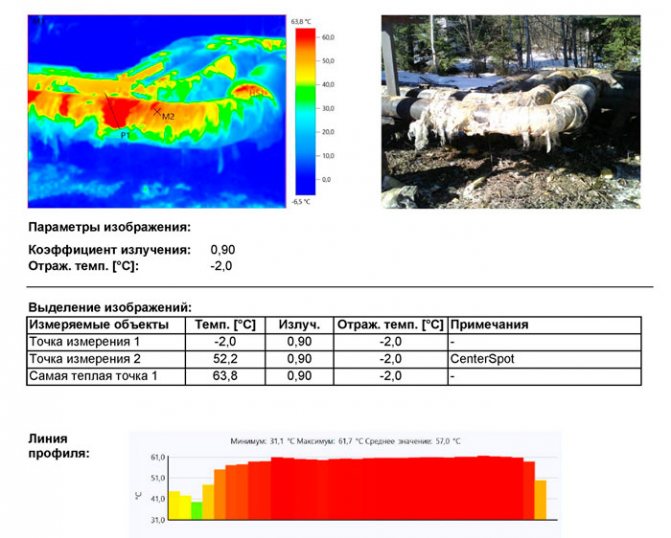
Partial destruction of thermal insulation of pipelines with a coolant. The maximum temperature in open areas was 63.8 ° C
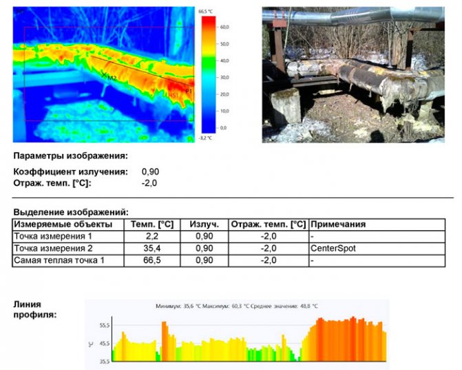
Partial destruction of thermal insulation of pipelines with a coolant. The maximum temperature in open areas was 66.5 ° C
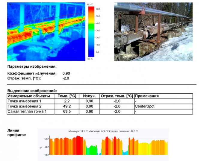
Partial destruction of thermal insulation of pipelines with a coolant. The maximum temperature in open areas was 63.5 ° C
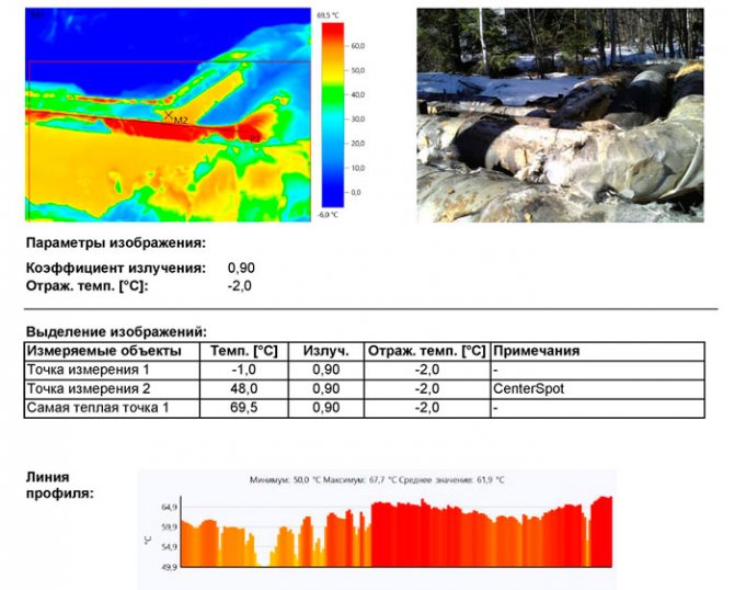
Partial destruction of thermal insulation of pipelines with a coolant. The maximum temperature in open areas was 69.5 ° C
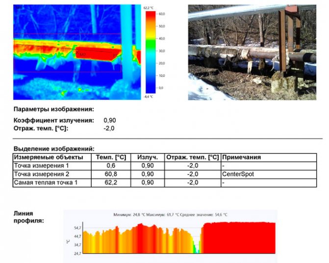
Partial destruction of thermal insulation of pipelines with a coolant. The maximum temperature in open areas was 62.2 ° C
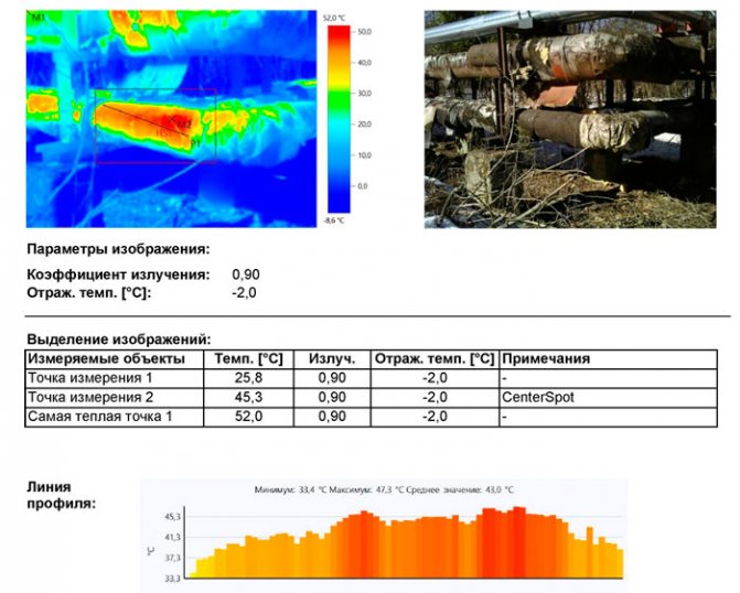
Partial destruction of thermal insulation of pipelines with a coolant. The maximum temperature in open areas was 52.0 ° C
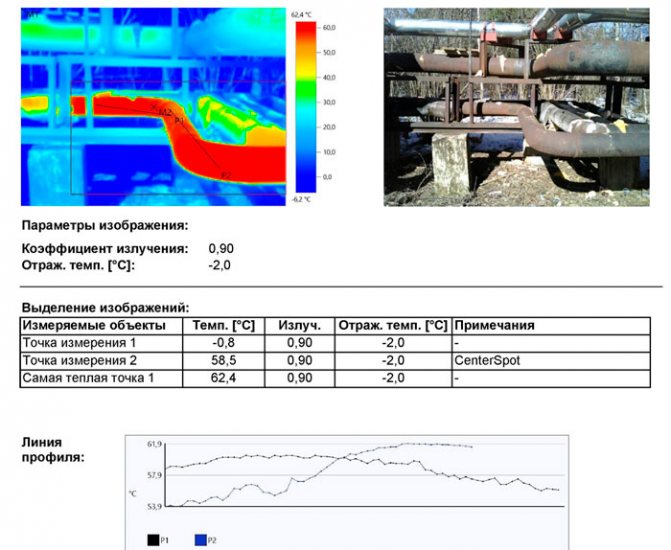
Open sections of pipelines without insulation. The maximum temperature in open areas was 62.4 ° C
Partial destruction of thermal insulation of pipelines with a coolant under the influence of the environment.
Learn about the survey of water supply systems.
Partial destruction of thermal insulation of pipelines with a coolant under the influence of the environment.
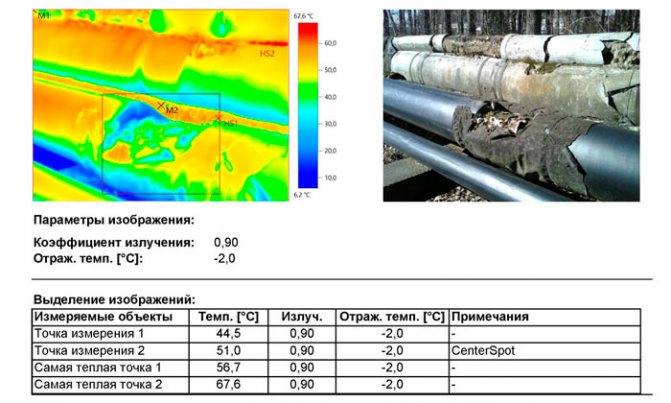
Partial destruction of thermal insulation of pipelines with a coolant. The maximum temperature in open areas was 67.6 ° C
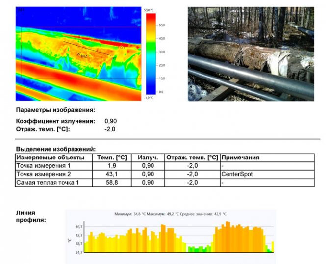
Partial destruction of thermal insulation of pipelines with a coolant. The maximum temperature in open areas was 58.8 ° C
Partial destruction of thermal insulation of pipelines with a coolant under the influence of the environment.
Determination of boiler output
To maintain the temperature difference between the environment and the temperature inside the house, an autonomous heating system is needed that maintains the desired temperature in every room of a private house.
The basis of the heating system is different types of boilers: liquid or solid fuel, electric or gas.
The boiler is the central unit of the heating system that generates heat. The main characteristic of the boiler is its power, namely the rate of conversion of the amount of heat per unit of time.
Having made calculations of the heat load for heating, we will obtain the required rated power of the boiler.
For an ordinary multi-room apartment, the boiler power is calculated through the area and specific power:
Рkotla = (Sroom * Rudelnaya) / 10where
- S rooms- the total area of the heated room;
- Rudellnaya- power density relative to climatic conditions.
But this formula does not take into account heat losses, which are sufficient in a private house.
There is another relationship that takes this parameter into account:
Рboiler = (Qloss * S) / 100where
- Rkotla- boiler power;
- Qloss- heat loss;
- S - heated area.
The rated output of the boiler must be increased. The stock is necessary if you plan to use the boiler for heating water for the bathroom and kitchen.

In most heating systems for private houses, it is recommended to use an expansion tank in which a supply of coolant will be stored. Every private house needs hot water supply
In order to provide for the power reserve of the boiler, the safety factor K must be added to the last formula:
Рboiler = (Qloss * S * K) / 100where
TO - will be equal to 1.25, that is, the estimated boiler output will be increased by 25%.
Thus, the power of the boiler makes it possible to maintain the standard air temperature in the rooms of the building, as well as to have an initial and additional volume of hot water in the house.
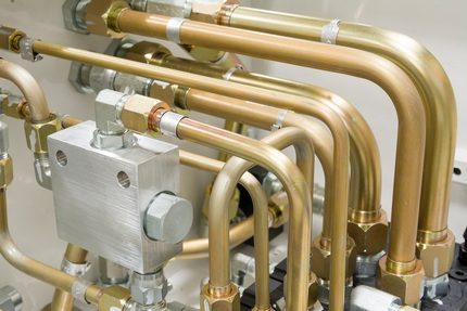
Brief description of the heating network
To cover the heat loads, a production and heating boiler house is used, the main fuel of which is natural gas.
Boiler room generates
- steam for technological needs - year-round
- hot water for heating needs - during the heating season and
- hot water supply - all year round.
- The project provides for the operation of the heating network according to a temperature schedule of 98/60 degrees. WITH.
The heating system connection diagram is dependent.
Heating networks, providing the transfer of heat energy for the needs of heating the entire village and hot water supply of its right-bank part, are installed in the above-ground and underground versions.
The heating network is ramified, dead-end.
The heating networks were commissioned in 1958. Construction continued until 2007.
Thermal insulation done
- mats made of glass wool 50 mm thick, with a cover layer of roll material,
- extruded polystyrene foam type TERMOPLEKS 40 mm thick, with a covering layer of galvanized sheet and expanded polyethylene 50 mm thick.
During the operation, some sections of the heating network were repaired with the replacement of pipelines and thermal insulation.
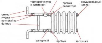
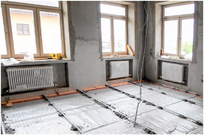
Features of the selection of radiators
Radiators, panels, underfloor heating systems, convectors, etc. are standard components for providing heat in a room. The most common parts of a heating system are radiators.
The heat sink is a special hollow modular type structure made of high heat dissipation alloy. It is made from steel, aluminum, cast iron, ceramics and other alloys. The principle of operation of a heating radiator is reduced to the radiation of energy from the coolant into the space of the room through the “petals”.
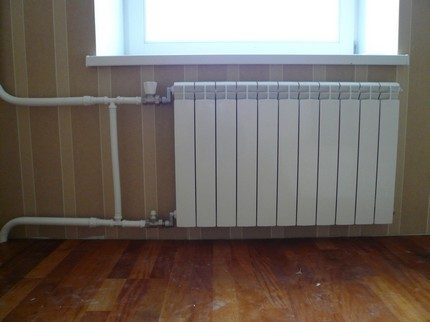
An aluminum and bimetallic heating radiator has replaced massive cast-iron radiators. Ease of production, high heat dissipation, good construction and design have made this product a popular and widespread tool for radiating heat indoors.
There are several methods for calculating heating radiators in a room. The list of methods below is sorted in order of increasing computational accuracy.
Calculation options:
- By area... N = (S * 100) / C, where N is the number of sections, S is the area of the room (m2), C is the heat transfer of one section of the radiator (W, taken from those passport or product certificate), 100 W is the amount of heat flow, which is necessary for heating 1 m2 (empirical value). The question arises: how to take into account the height of the ceiling of the room?
- By volume... N = (S * H * 41) / C, where N, S, C - similarly. H is the height of the room, 41 W is the amount of heat flux required to heat 1 m3 (empirical value).
- By odds... N = (100 * S * k1 * k2 * k3 * k4 * k5 * k6 * k7) / C, where N, S, C and 100 are similar. k1 - taking into account the number of chambers in the glass unit of the window of the room, k2 - thermal insulation of the walls, k3 - the ratio of the area of windows to the area of the room, k4 - the average subzero temperature in the coldest week of winter, k5 - the number of outer walls of the room (which “go out” to the street), k6 - type of room on top, k7 - ceiling height.
This is the most accurate way to calculate the number of sections. Naturally, fractional calculation results are always rounded to the next integer.
General Provisions
Any simple calculation method has a rather large error. However, from a practical point of view, it is important for us to ensure a guaranteed sufficient heat output. If it turns out to be more necessary even at the peak of the winter cold, so what?
In an apartment where heating is paid by area, the heat of the bones does not ache; and regulating throttles and thermostatic temperature regulators are not something very rare and inaccessible.
In the case of a private house and a private boiler, the price of a kilowatt of heat is well known to us, and it would seem that excess heating will hit your pocket. In practice, however, this is not the case. All modern gas and electric boilers for heating a private house are equipped with thermostats that regulate heat transfer depending on the temperature in the room.
The thermostat will prevent the boiler from wasting excess heat.
Even if our calculation of the power of heating radiators gives a significant error in a big way, we risk only the cost of a few additional sections.
By the way: in addition to the average winter temperatures, extreme frosts occur every few years.
There is a suspicion that due to global climatic changes, they will happen more and more often, so when calculating heating radiators, do not be afraid to make a big mistake.
Hydraulic calculation of water supply
Of course, the “picture” of calculating heat for heating cannot be complete without calculating such characteristics as the volume and speed of the heat carrier. In most cases, the coolant is ordinary water in a liquid or gaseous state of aggregation.
It is recommended to calculate the real volume of the heat carrier through the summation of all cavities in the heating system. When using a single-circuit boiler, this is the best option. When using double-circuit boilers in the heating system, it is necessary to take into account the consumption of hot water for hygienic and other domestic purposes.
The calculation of the volume of water heated by a double-circuit boiler to provide residents with hot water and heating the coolant is made by summing the internal volume of the heating circuit and the real needs of users in heated water.
The volume of hot water in the heating system is calculated using the formula:
W = k * Pwhere
- W - the volume of the heat carrier;
- P - heating boiler power;
- k - power factor (the number of liters per unit of power is 13.5, range - 10-15 liters).
As a result, the final formula looks like this:
W = 13.5 * P
The flow rate of the heating medium is the final dynamic assessment of the heating system, which characterizes the rate of circulation of the liquid in the system.
This value helps to estimate the type and diameter of the pipeline:
V = (0.86 * P * μ) / ∆Twhere
- P - boiler power;
- μ - boiler efficiency;
- ∆T - the temperature difference between the supply water and the return water.
Using the above methods of hydraulic calculation, it will be possible to obtain real parameters, which are the “foundation” of the future heating system.
On the selection and thermal calculation of heating devices
A number of issues were discussed at the round table, such as, for example, the creation of a verification system for engineering systems of buildings and structures, compliance by manufacturers, suppliers and retail chains with the requirements for protecting consumer rights, mandatory testing of heating devices with mandatory indication of the conditions for testing devices, development of design rules and the use of heating appliances. During the discussion, again, the unsatisfactory operation of the instruments was noted.
In this regard, I would like to note that the unsatisfactory operation of the heating system can be judged not only by heating devices... The reason is also possible in the lowered heat engineering data (in comparison with the design data) of the outer walls, windows, coatings, and in the supply of water to the heating system with a reduced temperature. All this should be reflected in the materials of a comprehensive assessment of the technical condition of the heating system.
The actual heat transfer of heating devices may be less than the required one for various reasons. Firstly, in reality, heating devices are separated from various types of premises by decorative fences, curtains, and furniture. Secondly, non-compliance with the requirements of the Rules for the technical operation of heating systems [1].
The heat dissipation of devices is influenced, for example, by the composition and color of the paint. Reduced heat transfer and radiators located in niches.
The method of thermal calculation of heating devices, given in the well-known designer's handbook [2], is currently invalid for a number of reasons.
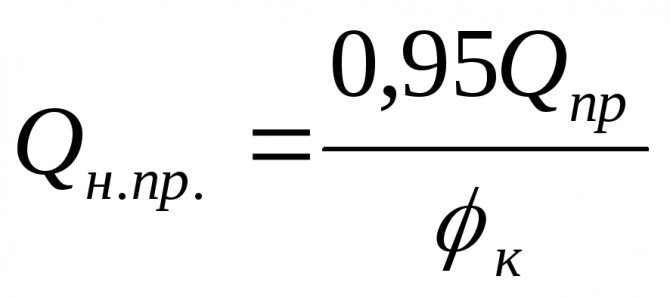
Currently, heating devices are often selected according to the value of its nominal heat flux, that is, without taking into account the complex coefficient of bringing the nominal heat flux to real conditions, depending on the heating system (one-pipe or two-pipe), the temperature of the coolant and air in the room, the value of which, as a rule , less than 1. The work presents the recommended thermal calculation of modern devices [3].
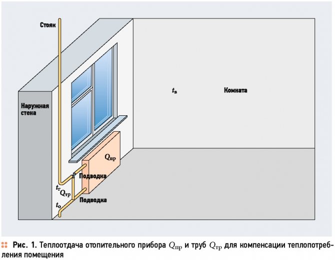
The selection of devices consists in determining the number of sections of a collapsible radiator or the type of a non-collapsible radiator or convector, the external heat-transfer surface of which must ensure the transfer of at least the required heat flux into the room (Fig. 1).
The calculation is carried out at the temperature of the coolant before and after the heater (in residential and public buildings, as a rule, water or non-freezing liquid is used), the heat consumption of the room Qnom, corresponding to the calculated heat deficit in it, referred to one heating device, at the estimated outside air temperature [ four].
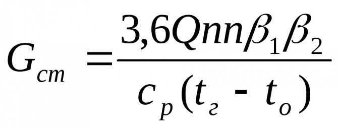
The estimated number of sections of collapsible radiators with sufficient accuracy can be determined by the following formula:
The type, length of non-separable radiators and convectors should be determined from the condition that their nominal heat flux Qpom should be no less than the calculated heat transfer Qopr:
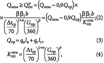
where Qopr is the calculated thermal power of the heater, W; qsecr is the calculated heat flux density of one section of the device, W; Qtr is the total heat transfer of the riser pipes, connections, laid openly within the premises, related to the heating device, W; β is a coefficient that takes into account the installation method, the location of the heater [2, 3] (when installing the device, for example, it is open near the outer wall β = 1, if there is a shield in front of the devices with slots in the upper part β = 1.4, and when located convector in the floor structure, the value of the coefficient reaches 2); β1 - coefficient taking into account the change in heat transfer from the radiator depending on the number of sections or the length of the device, β1 = 0.95-1.05; b - coefficient taking into account atmospheric pressure, b = 0.95-1.015; qв and qr - heat transfer of 1 m of vertical and horizontal openly laid pipes [W / m], taken for non-insulated and insulated pipes according to table. 1 [2, 3]; lw and lg - length of vertical and horizontal pipes within the premises, m; qnom and Qnom - the nominal heat flux density of one section of a collapsible or corresponding type of non-collapsible heating device, given in [3], in the Recommendations of the laboratory of heating devices "NIisantekhniki" (LLC "Vitaterm") and in the catalogs of device manufacturers, with a difference in the average temperature of the coolant and room air Δtav equal to 70 ° C, and with a water flow rate of 360 kg / h in the device; Δtav and Gpr - actual temperature difference 0.5 (tg + to) - tv and coolant flow [kg / h] in the device; n and p are experimental numerical indicators that take into account the change in the heat transfer coefficient of the device at the actual values of the average temperature difference and the flow rate of the coolant, as well as the type and scheme of connecting the device to the pipes of the heating system, adopted according to [3] or according to the Recommendations of the laboratory of heating devices "NIIsantekhniki"; tg, to and tв - the calculated values of the temperatures of the coolant before and after the device and the air in the given room, ° C; Kopotn is a complex coefficient for bringing the nominal heat flux to real conditions.
When choosing the type of heating device [4], it should be borne in mind that its length in buildings with high sanitary requirements should be at least 75%, in residential and other public buildings - at least 50% of the length of the skylight
The estimated flow rate of the heating medium passing through the heater [kg / h] can be determined by the formula:
The value of Qpom here corresponds to the heat load assigned to one heating device (when there are two or more of them in the room).
When choosing the type of heating device [4], it should be borne in mind that its length in buildings with increased sanitary and hygienic requirements (hospitals, preschool institutions, schools, homes for the elderly and disabled) should be at least 75%, in residential and other public buildings - not less than 50% of the length of the light opening.
Examples of the selection of heating devices
Example 1. Determine the required number of sections of the MC-140-M2 radiator, installed without a screen under the window sill of a 1.5 X 1.5 m window, if known: the heating system is two-pipe, vertical, pipe laying is open, nominal diameters of vertical pipes (risers) within the premises 20 mm, horizontal (connections to the radiator) 15 mm, the calculated heat consumption Qpom of the room No. 1 is 1000 W, the calculated supply water temperature tg and return water to are equal to 95 and 70 ° C, the air temperature in the room is tв = 20 ° C, the device is connected by the "top-down" scheme, the length of the vertical lw and horizontal lg pipes is 6 and 3 m, respectively. The nominal heat flux of one section qnom is 160 W.
Decision.
1. We find the flow rate of water Gpr passing through the radiator:
Indicators n and p are 0.3 and 0.02, respectively; β = 1.02, β1 = 1 and b = 1.
2. Find the temperature difference Δtav:
3. We find the heat transfer of pipes Qtr, using the tables of heat transfer of openly laid vertical and horizontal pipes:
4. Determine the number of sections Npr:
Four sections should be accepted for installation. However, the radiator length of 0.38 m is less than half the window size. Therefore, it is more correct to install a convector, for example, "Santekhprom Auto". The indices n and p for the convector are taken equal to 0.3 and 0.18, respectively.
The calculated heat transfer of the convector Qopr is found by the formula:
We accept a convector "Santekhprom Auto" type KSK20-0.918kA with a nominal heat flux Qnom = 918 W. The length of the convector casing is 0.818 m.
Example 2. Determine the required number of MC-140-M2 radiator sections at the calculated supply water temperature tg and return tо equal to 85 and 60 ° C. The rest of the initial data is the same.
Decision.
In this case: Δtav = 52.5 ° C; heat transfer of pipes will be
Six sections are accepted for installation. The increase in the required number of radiator sections in the second example is caused by a decrease in the calculated flow and return temperatures in the heating system.
According to calculations (example 5), one wall-mounted convector "Santechprom Super Auto" with a nominal heat flux of 3070 W can be accepted for installation. As an example - a convector KSK 20-3070k of medium depth with an angular steel valve body KTK-U1 and with a closing section. Convector casing length 1273 mm, total height 419 mm
The radiator length of 0.57 m is less than half the window size. Therefore, you should install a radiator of a lower height, for example, of the MC-140-300 type, the nominal heat flux of one section of which qnom is 0.12 kW (120 W).
We find the number of sections by the following formula:
We accept eight sections for installation. The radiator is 0.83 m long, which is more than half the window size.
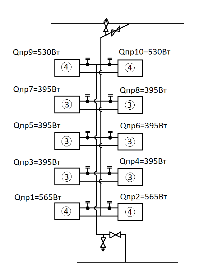
Example 3. Determine the required number of sections of the MC-140-M2 radiator, installed under window sills without a screen of two windows measuring 1.5 X 1.5 m with a wall, if known: the heating system is two-pipe, vertical, open pipe laying, nominal diameters of vertical pipes within the room 20 mm, horizontal (connections before and after the radiator) 15 mm, the calculated heat consumption of the room Qpom is 3000 W, the calculated temperatures of the supply tg and return water are 95 and 70 ° C, the air temperature in the room is tв = 20 ° C, the connection of the device
according to the "top-down" scheme, the length of the vertical lw and horizontal lg pipes is 6 and 4 m, respectively. Nominal heat flux of one section qnom = 0.16 kW (160 W). Decision.
1. Determine the flow rate of water Gpr passing through two radiators:
Indicators n and p are 0.3 and 0.02, respectively; β = 1.02, β1 = 1 and b = 1.
2. Find the temperature difference Δtav:
3. We find the heat transfer of pipes Qtr, using the tables of heat transfer of openly laid vertical and horizontal pipes:
4. Determine the total number of sections Npr:
We will accept for installation two radiators of 9 and 10 sections.
Example 4. Determine the required number of MC-140-M2 radiator sections at the calculated supply water temperature tg, and reverse to, equal to 85 and 60 ° C. The rest of the initial data is the same.
Decision.
In this case: Δtav = 52.5 ° C; heat transfer of pipes will be:
We will accept for installation two radiators of 12 sections.
Example 5. Determine the type of convector at the calculated supply water temperatures tp and return to equal to 85 and 60 ° C, and the calculated heat consumption of the room Qpom, equal to 2000 W. The rest of the initial data are shown in example 3: n = 0.3, p = 0.18.
In this case: Δtav = 52.5 ° C; heat transfer of pipes will be:
Then
It is possible to accept for installation one wall-mounted convector "Santekhprom Super Auto" with a nominal heat flux of 3070 W. Convector KSK 20-3070k of medium depth, as an example, with an angular steel valve body KTK-U1 and with a closing section. The length of the convector casing is 1273 mm, the total height is 419 mm.
It is also possible to install a KS20-3030 convector manufactured by NBBK LLC with a nominal heat flux of 3030 W and a casing length of 1327 mm.
Thermal design example
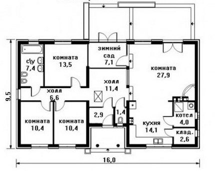
As an example of heat calculation, there is a regular 1-storey house with four living rooms, a kitchen, a bathroom, a “winter garden” and utility rooms.

The foundation is made of a monolithic reinforced concrete slab (20 cm), the outer walls are concrete (25 cm) with plaster, the roof is made of wooden beams, the roof is metal and mineral wool (10 cm)
Let's designate the initial parameters of the house, necessary for the calculations.
Building dimensions:
- floor height - 3 m;
- small window of the front and back of the building 1470 * 1420 mm;
- large facade window 2080 * 1420 mm;
- entrance doors 2000 * 900 mm;
- rear doors (exit to the terrace) 2000 * 1400 (700 + 700) mm.
The total width of the building is 9.5 m2, the length is 16 m2. Only living rooms (4 pcs.), A bathroom and a kitchen will be heated.
To accurately calculate the heat loss on the walls from the area of the external walls, you need to subtract the area of all windows and doors - this is a completely different type of material with its own thermal resistance
We start by calculating the areas of homogeneous materials:
- floor area - 152 m2;
- roof area - 180 m2, taking into account the attic height of 1.3 m and the width of the run - 4 m;
- window area - 3 * 1.47 * 1.42 + 2.08 * 1.42 = 9.22 m2;
- door area - 2 * 0.9 + 2 * 2 * 1.4 = 7.4 m2.
The area of the outer walls will be 51 * 3-9.22-7.4 = 136.38 m2.
Let's move on to calculating heat loss for each material:
- Qpol = S * ∆T * k / d = 152 * 20 * 0.2 / 1.7 = 357.65 W;
- Qroof = 180 * 40 * 0.1 / 0.05 = 14400 W;
- Qwindow = 9.22 * 40 * 0.36 / 0.5 = 265.54 W;
- Qdoor = 7.4 * 40 * 0.15 / 0.75 = 59.2 W;
And also Qwall is equivalent to 136.38 * 40 * 0.25 / 0.3 = 4546. The sum of all heat losses will be 19628.4 W.
As a result, we calculate the boiler power: Рboiler = Qloss * Sheat_room * К / 100 = 19628.4 * (10.4 + 10.4 + 13.5 + 27.9 + 14.1 + 7.4) * 1.25 / 100 = 19628.4 * 83.7 * 1.25 / 100 = 20536.2 = 21 kW.
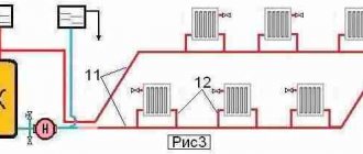
We will calculate the number of radiator sections for one of the rooms. For everyone else, the calculations are the same. For example, a corner room (left, bottom corner of the diagram) is 10.4 m2.
Hence, N = (100 * k1 * k2 * k3 * k4 * k5 * k6 * k7) / C = (100 * 10.4 * 1.0 * 1.0 * 0.9 * 1.3 * 1.2 * 1.0 * 1.05) /180=8.5176=9.
This room requires 9 sections of a heating radiator with a heat output of 180 W.
We proceed to calculating the amount of coolant in the system - W = 13.5 * P = 13.5 * 21 = 283.5 liters. This means that the speed of the coolant will be: V = (0.86 * P * μ) / ∆T = (0.86 * 21000 * 0.9) /20=812.7 liters.
As a result, a complete turnover of the entire volume of the coolant in the system will be equivalent to 2.87 times per hour.
A selection of articles on thermal calculation will help determine the exact parameters of the elements of the heating system:
- Calculation of the heating system of a private house: rules and calculation examples
- Thermal calculation of a building: specifics and formulas for performing calculations + practical examples
Calculation of a finned radiator as an element of a heat exchanger with forced convection.
A technique is presented, using the example of an Intel Pentium4 Willamette 1.9 GHz processor and a B66-1A cooler manufactured by ADDA Corporation, which describes the procedure for calculating finned radiators designed to cool heat-generating elements of electronic equipment with forced convection and flat thermal contact surfaces with a power of up to 100 W. The technique allows for the practical calculation of modern high-performance small-sized devices for heat removal and apply them to the entire spectrum of radioelectronic devices in need of cooling.
Parameters set in the initial data:
P
= 67 W, the power dissipated by the cooled element;
qwith
= 296 ° K, the temperature of the medium (air) in degrees Kelvin;
qbefore
= 348 ° K, the limiting temperature of the crystal;
qR
= nn ° K, average temperature of the heatsink base (calculated during the calculation);
H
= 3 10-2 m, height of the radiator fin in meters;
d
= 0.8 10-3 m, rib thickness in meters;
b
= 1.5 10-3 m, the distance between the ribs;
lm
= 380 W / (m ° K), coefficient of thermal conductivity of the radiator material;
L
= 8.3 10-2 m, the size of the radiator along the edge in meters;
B
= 6.9 10-2 m, the size of the radiator across the fins;
BUT
= 8 10-3 m, the thickness of the radiator base;
V
³ 2 m / s, air speed in the radiator channels;
Z
= 27, the number of radiator fins;
uR
= nn K, the overheating temperature of the heatsink base, is calculated during the calculation;
eR
= 0.7, the degree of blackness of the radiator.
It is assumed that the heat source is located in the center of the radiator.
All linear dimensions are measured in meters, temperature in Kelvin, power in watts, and time in seconds.
The design of the radiator and the parameters required for calculations are shown in Fig. 1.
Picture 1.
Calculation procedure.
1. Determine the total cross-sectional area of the channels between the ribs by the formula:
Sк = (Z - 1) · b · H [1]
For the accepted initial data - Sk = (Z - 1) b H = (27-1) 1.5 10-3 3 10-2 = 1.1 10-3 m2
For a central installation of the fan, the air flow exits through the two end surfaces and the cross-sectional area of the ducts doubles to 2.2 10-3 m2.
2. We set two values for the temperature of the base of the radiator and perform the calculation for each value:
qр = {353 (+ 80 ° С) and 313 (+ 40 ° С)}
From here, the overheating temperature of the radiator base is determined. uR
regarding the environment.
uр = qр - qс [2]
For the first point, uр = 57 ° K, for the second, uр = 17 ° K.
3. Determine the temperature q
required to calculate the Nusselt (Nu) and Reynolds (Re) criteria:
q = qс + P / (2 · V · Sк · r · Cр) [3]
Where: qwith
–
ambient air temperature, environment,
V
- air speed in the channels between the ribs, in m / s;
Sto
- the total cross-sectional area of the channels between the ribs, in m2;
r
- air density at temperature
q
Wed, in kg / m3,
q
cf = 0.5 (
qp +qwith)
;
CR
- heat capacity of air at temperature
q
Wed, in J / (kg x ° K);
P
- the power dissipated by the radiator.
For the accepted initial data - q = qс + P / (2 V Sк r Cр) = 296 K + 67 / (2 2 m / s 1.1 10-3m2 1.21 1005) = 302 , 3 ° C (29.3 ° C)
* The value for a given finned radiator with a central fan installation, V
from calculations 1.5 - 2.5 m / s (See Appendix 2), from publications [L.3] about 2 m / s. For short, expanding channels, such as the Golden Orb cooler, the cooling air speed can reach 5 m / s.
4. Determine the values of the Reynolds and Nusselt criteria required to calculate the heat transfer coefficient of the radiator fins:
Re = V · L / n [4]
Where: n
- coefficient of kinematic viscosity of air at
qwith,m2/with
from Appendix 1, table 1.
For the accepted initial data - Re = VL / n = 2 8.3 10-2 / 15.8 10-6 = 1.05 104
Nu = 0.032 Re 0.8 [5]
For the accepted initial data - Nu = 0.032 Re 0.8 = 0.032 (2.62 104) 0.8 = 52.8
5. Determine the coefficient of convective heat transfer of the radiator fins:
ato
=Nu·lat/
L W / (m
2
K) [6]
Where, l
- coefficient of thermal conductivity of air (W / (m deg)), at
qwith
from Appendix 1, table1.
For the accepted initial data - ak = Nu · lv / L = 52.8 · 2.72 10-2 / 8.3 10-2 = 17.3
6. Determine the auxiliary coefficients:
m = (2 · ak / lm · d) 1/2 [7]
we determine the value of mh and the tangent of the hyperbolic th (mh).
For the accepted initial data - m = (2 ak / lm d) 1/2 = (2 17.3 / (380 0.8 10-3)) 1/2 = 10.6
For the accepted initial data - m · H = 10.6 · 3 10-2 = 0.32; th (m H) = 0.31
7. Determine the amount of heat given off by convection from the radiator fins:
Prc = Z · lm · m · Sр · uр · th (m · H) [8]
Where: Z
- number of ribs;
lm
= coefficient of thermal conductivity of the radiator metal, W / (m
·
° K);
m
- see formula 7;
SR
- cross-sectional area of the radiator fin, m2,
Sр = L · d [9]
uR
- overheating temperature of the radiator base.
Sp = L d = 8.3 10-2 0.8 10-3 = 6.6 10-5 m2
Prk = Z · lm · m · Sр · uр · th (m · H) = 27 · 380 · 10.6 · 6.6 10-5 · 57 · 0.31 = 127 W.
8. Determine the average temperature of the radiator fin:
qср = (qр / 2) [1 + 1 / ch (m · H)] [10]
Where: ch
(mH)
- the cosine is hyperbolic.
For the accepted initial data - qср = (qр / 2) [1 + 1 / ch (m · H)] = (353/2) [1 + 1 / 1.05] = 344 ° K (71 ° С)
* The magnitude of the tangent and cosine of hyperbolic is calculated on an engineering calculator by sequentially performing the "hyp" and "tg" or "cos" operations.
9. Determine the radiant heat transfer coefficient:
al = eр · f (qср, qс) · j [11]
f (qср, qс) = 0.23 [5 10-3 (qср + qс)] 3
For the accepted initial data - f (qcr, qc) = 0.23 [5 10-3 (qcr + qc)] 3 = 0.23 [5 10-3 (335 + 296)] 3 = 7.54
Irradiance coefficient:
j = b / (b + 2h)
j = b / (b + 2H) = 1.5 10-3 / (1.5 10-3 + 3 10-2) = 0.048
al = eрf (qav, qs) j = 0.7 x 7.54 x 0.048 = 0.25 W / m2 K
10. Determine the surface area of the radiating heat flux:
Sl = 2 L [(Z -1) · (b + d) + d] +2 H · L · Z (m2) [12]
For the accepted initial data - Sl = 2 L [(Z -1) · (b + d) + d] +2 H · L · Z = 0.1445 m2
11. Determine the amount of heat given off through radiation:
Pl = al · Sl (qav - qc) [13]
For the accepted initial data - Pl = alSl (qav - qc) = 0.25 0.1445 (344 - 296) = 1.73 W
12. The total amount of heat given off by the radiator at a given radiator temperature qр = 353K:
P = Prk + Pl [14]
For the accepted initial data - P = Prk + Pl = 127 + 1.73 = 128.7 W.
13. We repeat the calculations for the heatsink temperature q
p = 313K, and we plot the thermal characteristic of the calculated radiator at two points. For this point, P = 38W. Here, along the vertical axis, the amount of heat given off by the radiator is deposited
PR
, and the horizontal temperature of the radiator is
qR
.
Figure 2
From the resulting graph, we determine for a given power of 67W, qR
= 328 ° K or 55 ° C.
14. According to the heat characteristic of the radiator, we determine that for a given power PR
= 67W, heatsink temperature
qR
= 328.5 ° C. Radiator overheat temperature
uR
can be determined by formula 2.
It is equal to uр = qр - qс = 328 - 296 = 32 ° K.
15. Determine the temperature of the crystal and compare it with the limit value set by the manufacturer
qto
=q
p + P (
r
pc +
r
pr) ° K = 328 + 67 (0.003 + 0.1) = 335 (62 ° C), [15]
Where:
qR
–
temperature of the base of the radiator for a given design point,
R
- the result of calculation by formula 14,
r
pc - thermal resistance of the processor case - crystal, for this heat source is 0.003 K / W
r
pr - thermal resistance of the case-radiator, for a given heat source is equal to 0.1K / W (with heat-conducting paste).
The result obtained is below the maximum temperature determined by the manufacturer, and is close to the data [L.2] (about 57 ° C). In this case, the temperature of overheating of the crystal relative to the ambient air in the above calculations is 32 ° C, and in [L.2] 34 ° C.
In general terms, the thermal resistance between two flat surfaces when using solders, pastes and adhesives:
r =
d
to
lk-1
·
Scont
-1
[16]
Where: d
k is the thickness of the gap between the radiator and the casing of the cooled unit filled with heat-conducting material in m,
lto
- coefficient of thermal conductivity of a heat-conducting material in the gap W / (m K),
Scont
Is the area of the contact surface in m2.
The approximate value of rcr with sufficient tightening and without gaskets and lubricants is
rcr = 2.2 / Scont
When using pastes, the thermal resistance drops by about 2 times.
16. Compare qto
with
qbefore
, we received a radiator providing
qto
= 325 ° K, less
qbefore=
348 ° K, - the given radiator provides the thermal mode of the unit with a margin.
17. Determine the thermal resistance of the calculated heatsink:
r =
u
R
/ P (° K / W) [17]
r = uр / P (° / W) = 32/67 = 0.47 ° / W
Findings:
The calculated heat exchanger provides heat power removal of 67W at an ambient temperature of up to 23 ° C, while the crystal temperature of 325 ° K (62 ° C) does not exceed 348 ° K (75 ° C) permissible for this processor.
The use of a special surface treatment to increase the output of thermal power through radiation at temperatures up to 50 ° C turned out to be ineffective and cannot be recommended, because does not pay off the costs.
I would like this material to help you not only calculate and manufacture a modern small-sized highly efficient heat exchanger, similar to those that are widely used in computer technology, but also competently make decisions on the use of such devices in relation to your tasks.
Constants for calculating the heat exchanger.
Table 1
| qs, K (° C) | l *10-2 W / (m K) | n * 10 6 m 2 / sec | Avg J / (kg * K) | r , kg / m 2 |
| 273 (0) td> | 2,44 | 13,3 | 1005 | 1,29 |
| 293 (20) | 2,59 | 15,1 | 1005 | 1,21 |
| 333 (60) | 2,9 | 19 | 1005 | 1,06 |
| 373 (100) | 3,21 | 23,1 | 1009 | 0,95 |
The values of the constants for intermediate temperatures, in a first approximation, can be obtained by plotting the graphs of the functions for the temperatures indicated in the first column.
Appendix 2.
Calculation of the speed of movement of air cooling the radiator.
The speed of movement of the coolant during forced convection in gases:
V = Gv / Sк
Where: Gv is the volumetric flow rate of the coolant, (for a 70x70 fan, Sp = 30 cm2, 7 blades, Rem = 2.3 W, w = 3500 rpm, Gv = 0.6-0.8 m3 / min. Or actually 0 , 2-0.3 or V = 2m / sec),
Sк - channel cross-sectional area free for passage.
Considering that the flow area of the fan is 30 cm2, and the area of the radiator channels is 22 cm2, the air blowing speed is determined to be lower, and will be equal to:
V = Gv / S = 0.3 m3
/ min / 2.2 10
-3
m
2
= 136 m / min = 2.2 m / s.
For calculations, we take 2 m / s.
Literature:
- Handbook of the designer REA, under the editorship of RG Varlamov, M, Soviet radio, 1972;
- Handbook of the CEA designer, ed. By RG Varlamov, M, Soviet radio, 1980;
- https://www.ixbt.com/cpu/, Coolers for Socket 478, Spring-Summer 2002, Vitaly Krinitsin
, Published - July 29, 2002;
- https://www.ixbt.com/cpu/, Measuring air velocities behind cooling fans and coolers, Alexander Tsikulin, Alexey Rameykin, Published - August 30, 2002.
prepared in 2003 based on materials L.1 and 2
Sorokin A.D.
This technique can be downloaded in PDF format here.
Precise calculation of heat output
For this, correction factors are used:
- K1 depends on the type of windows. Two-chamber double-glazed windows correspond to 1, ordinary glazing - 1.27, three-chamber windows - 0.85;
- K2 shows the degree of thermal insulation of the walls. It is in the range from 1 (foam concrete) to 1.5 for concrete blocks and masonry in 1.5 bricks;
- K3 reflects the ratio between the area of the windows and the floor. The more window frames there are, the greater the heat loss. At 20% glazing, the coefficient is 1, and at 50% it increases to 1.5;
- K4 depends on the minimum temperature outside the building during the heating season. A temperature of -20 ° C is taken as a unit, and then 0.1 is added or subtracted for every 5 degrees;
- K5 takes into account the number of exterior walls. The coefficient for one wall is 1, if there are two or three, then it is 1.2, when four - 1.33;
- K6 reflects the type of room that is located above a certain room. If there is a residential floor on top, the correction value is 0.82, a warm attic - 0.91, a cold attic - 1.0;
- K7 - depends on the height of the ceilings. For a height of 2.5 meters, this is 1.0, and for 3 meters - 1.05.
When all the correction factors are known, the power of the heating system is calculated for each room using the formula:
Thermal calculation of a room and a building as a whole, heat loss formula
Thermal calculation
So, before calculating the heating system for your own home, you must find out some data that relate to the building itself.
From the project of the house, you will learn the dimensions of the heated premises - the height of the walls, the area, the number of window and door openings, as well as their dimensions. How the house is located in relation to the cardinal points. Be aware of the average winter temperatures in your area. What material is the building itself constructed from?
Particular attention to exterior walls. Be sure to determine the components from the floor to the ground, which includes the foundation of the building. The same applies to the top elements, i.e. the ceiling, roof and slabs.
It is these parameters of the structure that will allow you to proceed to the hydraulic calculation. Let's face it, all of the above information is available, so there shouldn't be any problems with collecting it.
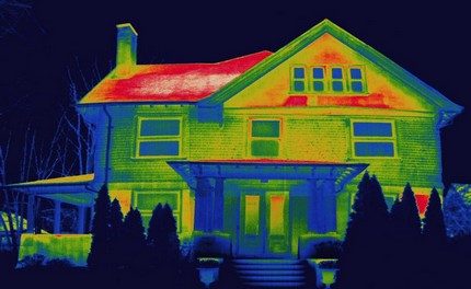
Comprehensive heat load calculation
In addition to the theoretical solution of issues related to thermal loads, a number of practical measures are carried out during the design. Comprehensive heat engineering surveys include thermography of all building structures, including ceilings, walls, doors, windows. Thanks to this work, it is possible to determine and record various factors that affect the heat loss of a house or industrial building.
Thermal surveys provide the most reliable data on heat loads and heat losses for a particular building over a certain period of time. Practical measures make it possible to clearly demonstrate what theoretical calculations cannot show - problem areas of the future structure.
From all of the above, we can conclude that the calculations of heat loads for hot water supply, heating and ventilation, similar to the hydraulic calculation of the heating system, are very important and they should certainly be performed before the start of the arrangement of the heat supply system in your own house or at a facility for another purpose. When the approach to work is done correctly, the trouble-free functioning of the heating structure will be ensured, and at no extra cost.
Video example of calculating the heat load on the heating system of a building: