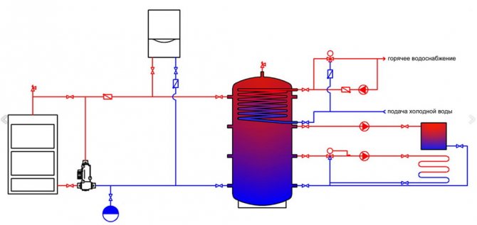
Types of boilers
Types of boiler equipment:
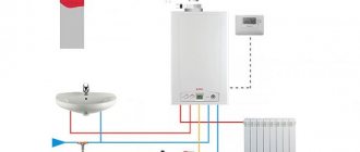
- gas. Highly effective, but not worth making at home. The units are classified as devices of increased hazard level. Creation requires skills, technology;
Gas boiler
- electric boilers. Unpretentious in terms of creation, operation. You can make your own heater. There are no increased safety requirements;
- liquid fuel. The construction is simple. Any man can handle the work. Difficulty in adjusting the nozzles;
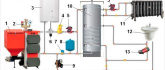
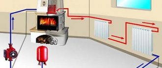
- solid fuel. Effective, versatile. Easy to operate and manufacture. Easily modified, rebuilt for another fuel. The units are also used for heating industrial areas.
It is important to choose the material from which the electric boiler will be made.
Heat-resistant stainless steel has good technical parameters. But she's dear. Equipment is required to process the material. You can choose cast iron.
When making your own, it is better to take sheet steel or a pipe with a thickness of at least 4 mm. Cast iron properties are good. Simple, easy to handle. Ordinary household devices can handle it.
Where to buy thermostats for heating boilers
You can buy thermostats for gas boilers, electric and solid fuel heating equipment at specialized points for the sale of heating equipment, as well as on websites and in online stores for the sale of elements of heating systems. The catalogs contain a huge selection of modern thermostats of various types from leading manufacturers. All devices are accompanied by a manufacturer's warranty.
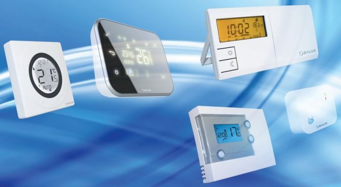
The modern market offers a huge selection of temperature controllers, both simple and the latest models.
The product range includes wired and wireless models, mechanical and electronic thermostats for solid fuel boilers, gas, electric and diesel installations, as well as convectors, infrared heaters and underfloor heating systems. All products from the catalog have quality certificates.
You can place an order and buy a thermostat for heating using a convenient search system on the Internet resource. Here you can not only familiarize yourself with the functions and appearance of the devices, but also consult with experts about the compatibility of devices with a specific type of heating equipment. Experienced managers are ready to share any necessary information regarding thermostats and their functionality.

By purchasing a thermostat through the online store, you will receive a high-quality device and expert advice
The advantage of online shopping is also that it is possible to get acquainted with the cost of devices in different companies and make a comparative review of prices. Choosing a thermostat, you can get competent advice on its installation, connection and configuration. Some companies offer services for the installation of the device and its adjustment. All questions you are interested in can be clarified by the phone numbers posted in the contact section.
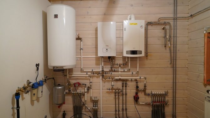
Features of electric boilers
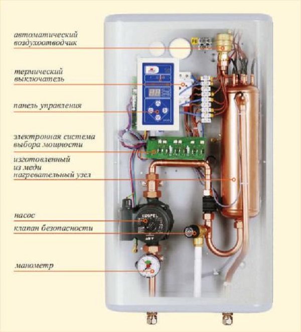
The peculiarity of the electric boiler is a heat exchanger with a heating element for heating water. A pump is used to organize forced circulation. There is an inlet for a cold one, an outlet for a hot coolant.
Design
The mechanism of operation of the heating unit is simple. Cold water is supplied to the heat exchanger. The heating element is heated by electric current. Thanks to the circulation pump, the liquid is distributed to the heating radiators.
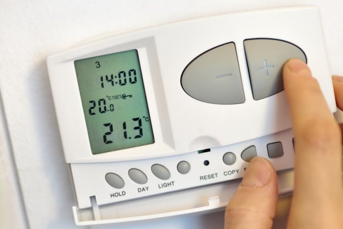
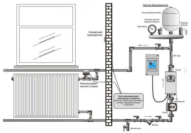
What temperature should I set?
The logic of work here is as follows. In the factory settings, the boiler heats water according to the temperature of the coolant.
By installing a remote thermostat, we thereby give it a command to heat the water not as the boiler wants, but according to the thermostat settings, i.e. to a certain temperature in a particular room.
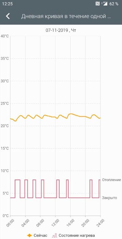
With normal house insulation and minimal heat loss, a gas boiler with a thermostat will work only 3-4 hours per day.
If the thermostat after installation did not affect the operating time of the boiler in any way, then most likely the gas appliance is set to a lower temperature than necessary. The regulator sensor simply does not have time to warm up to the desired value and work, while t of the coolant has already reached a predetermined threshold.
The instructions separately prescribe the minimum t on the boiler when using an external thermostat. As a rule, it should be at least 65 degrees.
Initially, it is recommended to set the design temperature on the heating device, which completely covers the heat loss of the building. When these heat losses are not known, values from 60 to 70C are taken for a standard heating system.
If you live in a relatively warm climate, and in winter the temperature in the batteries does not rise above 45C, you will still have to increase it to work with the thermostat.
Some people ask the question, what is the point in installing a regulator and how does this lead to savings?
- firstly, the boiler taps less, heats up the system faster

- secondly, at a higher temperature of the coolant, the heat in the rooms lasts longer
- and the maximum efficiency of batteries is observed precisely at t 65C-70C, and not at 45C
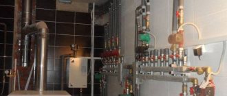
Automation, electrical for manufacturing
The electrical part is responsible for the normal operation of the boiler equipment. An electrical panel is assembled for work, a three-phase input. The electrical panel is usually metal Comprises:
- toggle switch;
- machine gun;
- control buttons;
- relay;
- magnetic starter.
Automation is designed to simplify, ease of control of the unit. Responsible for the safety of the equipment.
Automation
Sensors can be used. They are installed to maintain a comfortable microclimate according to the specified parameters. In case of deviations from the normal operation of the heating system, the sensors turn off everything. Allows you to secure the owners, save property.


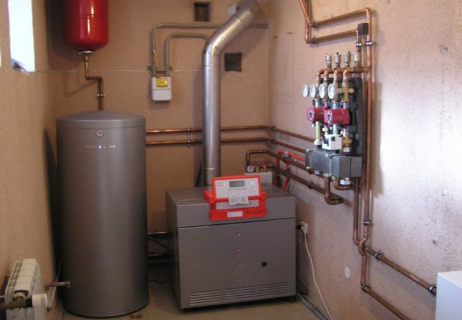
Assembly and installation of an electric boiler
In creating an electric boiler you will need:
- Three-phase heating element
- A segment of a thick-walled steel pipe, half a meter long, with a diameter of 219 mm.
- Steel sheet 2 mm thick (for lids).
To provide the necessary body tightness you will need to weld steel covers on both sides of the pipe. In the one that will be located at the top of the device, you need to make a hole with a diameter 40-50 mmfor hot water entering the heating system. A hole is also created in the lower part of the pipe in the side part, into which the chilled heat carrier. Opposite it or on the bottom cover, a heating element is mounted.
Additionally, an electric pump should be installed in the chilled water supply pipe, which will ensure the necessary water circulation in the system. Installed ball valves will allow you to shut off the electric boiler, repair without having to drain all the water from the system.
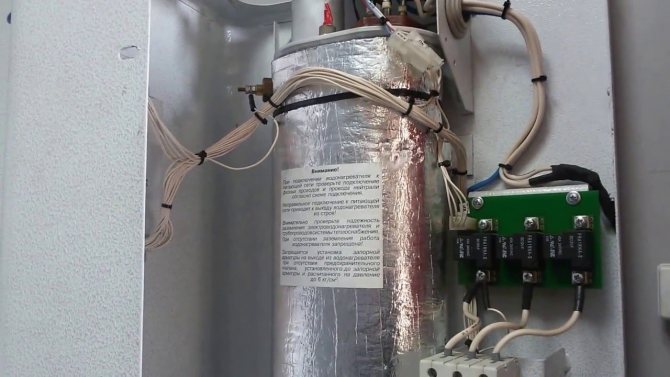
The electrical part ensures the operation of the unit. It will require assembly of the electrical panel. If the house does not have a three-phase input, you will need to connect it. The metal shield contains a magnetic starter, an automatic machine, a toggle switch, a relay, and buttons for controlling the boiler. The shield is mounted by a qualified specialist. In addition to the shield, grounding is required. A bolt is welded to the metal pin. The structure is placed above the floor. The wire is screwed to the bolt and passed to the electrical panel. Quality of work grounding is checked annually by a specialized organization with the recording of the measurement results in the protocol.
Electric boiler circuit:
- hot water pipe;
- body;
- tubular electric heater;
- chilled water inlet pipe;
- upper flange with gasket for sealing;
- pallet;
- bottom flange;
- pallet cover;
- bottom case cover;
- hole for bringing the electrical cord;
- gasket.
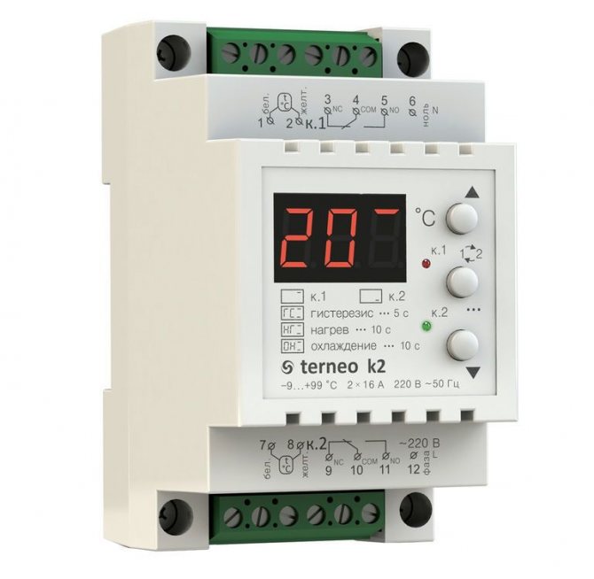
Electrical diagram:
- A - AP-50-3MT (automatic);
- MP - magnetic starter;
- П, С - buttons;
- T - toggle switch;
- Р - relay;
- Pr - fuse;
- TR - TR-0M5-03 (temperature sensor).
Installation of additional automatic systems makes it possible to provide work safety electric boilers and ease of use. Special sensors allow you to set a comfortable temperature in the house, turn off the system in case emergency.
What to consider when assembling a structure
The electric boiler must have a built-in electrical cabinet. It houses input devices, metering, protection, monitoring the operation of the heating unit. The function of switching the operating modes of the heating system is provided.
The electrical cable from the boiler equipment is fed into the electrical panel. The boiler is connected to the input machine.
Depending on the area of the room, you need to calculate the power of a homemade electric boiler. For 1 sq. m of area accounts for 0.1 kW of thermal power of the heating device. To create a heating system for a house with an area of 100 sq. m you need to make a boiler with a capacity of 10 kW.
The thermal calculation for the house must be done immediately. The cross-section of the wire, the elements of the boiler device, and the automation depend on the power.
It is necessary to lay an electric cable on the territory of the house according to safety rules. If the structure is made of wood, the cable is laid openly or in pipes. For buildings made of stone, brick, foam block, the wire is laid hidden or in boxes.
Homemade boiler
Any twisting, soldering, welding not provided for by the design of the boiler equipment is prohibited.
The boiler requires strict compliance with safety measures.
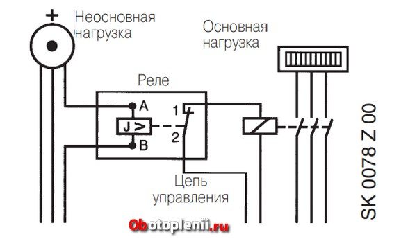
Load relay for electric boilers
These are special devices produced by manufacturers of heating boilers for their boilers. For example, relay HJ 103T for Therm boilers. This relay monitors the total power of the house network, and in case of its overestimation, it does not turn off the priority circuits, but regulates the power of the heating boiler, usually in steps.
I repeat once again, these relays work only with "their" heating boilers, which have terminals for their connection.
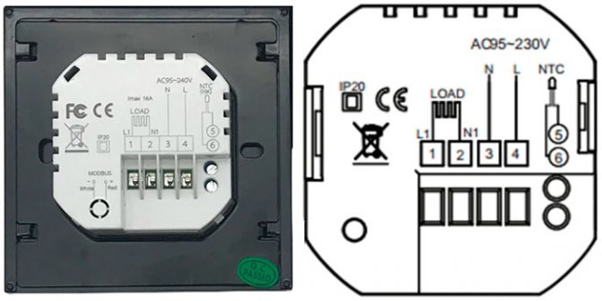
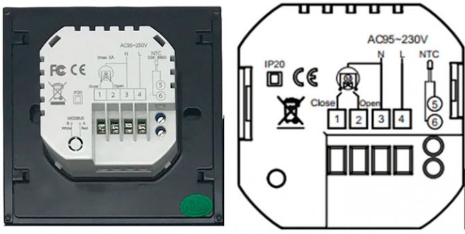
General connection principle for load control devices
The relays that monitor the total network load will be connected after the input circuit breaker and loads.
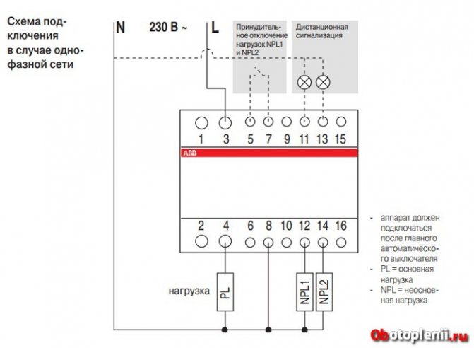
Priority switches are included between main and non-main loads.
The HJ 103T relay for Therm boilers is mounted on a DIN rail. It is 6 modules in width. A relay is installed after the input circuit breaker. There are terminals L1, L2 and L3 for connection. The boiler has contacts 5, 6, 7.
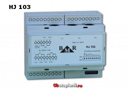
Boiler contacts 3 and 4 are connected to a start relay that disconnects another load operating with the boiler, for example, a boiler. Contacts 1, 2 are phase and zero, coming from the input automaton.
Step-by-step manufacturing instructions
Tools, materials should be at hand. You can get to work:
- Take the cut piece of metal pipe. Cut threads on both sides. On one side, a sleeve with electrodes is inserted, on the other, a plug.
- It is necessary to weld the threaded pipes. They will be the fasteners for the thermal communication of the system.
- Two bolts are welded to the pipe. The first is for the "neutral wire", the second is for the ground loop.
- For the well-coordinated work of the resulting product with a common heating system, pipes are supplied to the branch pipes.
- The electrode is connected to the phase conductor terminal.
- The terminal of the "neutral wire", the ground wire, is connected to the previously welded bolted connections.
- You can start installing the pressure gauge, fuse system.
- After connecting the automation system, you can start connecting to the dashboard.
Boiler arrangement:
You can independently make an electric boiler with heating elements. For this, a tank is selected in which the heating elements are installed. They are bought in the store. The amount depends on the case, heating area. More often two, three. Products include a threaded head.
The boiler body is a metal pipe. On the side, nozzles for supply and return are soldered. It is better to install heating elements from above to facilitate replacement. You don't have to drain the water. To eliminate the problem of air accumulation, an automatic gas vent is provided.
Nuts are screwed onto the installed heating elements and welded. A pipe for draining water is installed at the bottom of the body. Threads are cut on the branch pipes. It will allow you to bring the pipes of the heating system to the electric boiler.
The unit is installed on the heating circuit, connected to the electrical network. The connection of the device to the panel, the machine is identical. The power of the device is being calculated.
Safety regulations
Before we move on to the main part of the heating installation, I would like to pay attention to the safety of electrical work.
At first, the connection of the electric heating boiler must be carried out with the electricity turned off.
Secondly, it must be installed at a certain distance from other objects, namely:
- there must be at least 5 cm of free space between the body and the walls;
- the front panel must be accessible for maintenance, 70 cm of free space is enough;
- the distance to the ceiling is not less than 80 cm;
- the distance to the floor is not less than 50 cm (if the electric boiler is suspended);
- the distance to the nearest pipes is at least 50 cm.
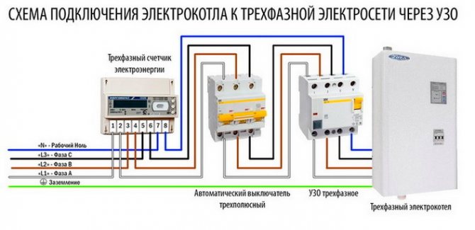
Thirdly, the network must be three-phase (380 V) in order to reduce the current loads on the wiring. When using a single-phase network to connect a powerful boiler, the wiring may not withstand, as a result of which it will spontaneously ignite and short circuit.
Fourth, all wire connections must be sealed and protected from water. The ingress of water on the contacts can occur when the pipeline is damaged (for example, the connecting sleeve connected to the unit bursts) and when condensate drains from the ceiling (in an unheated room). It is also recommended to protect the cable with a corrugation or a cable channel made of self-extinguishing material. In the event of a wire fire, these products will prevent the spread of the flame.
Do-it-yourself home heating control automation. Part 3
We continue to talk about a home heating control system using a timer-thermostat NM8036 (beginning here, continued here).
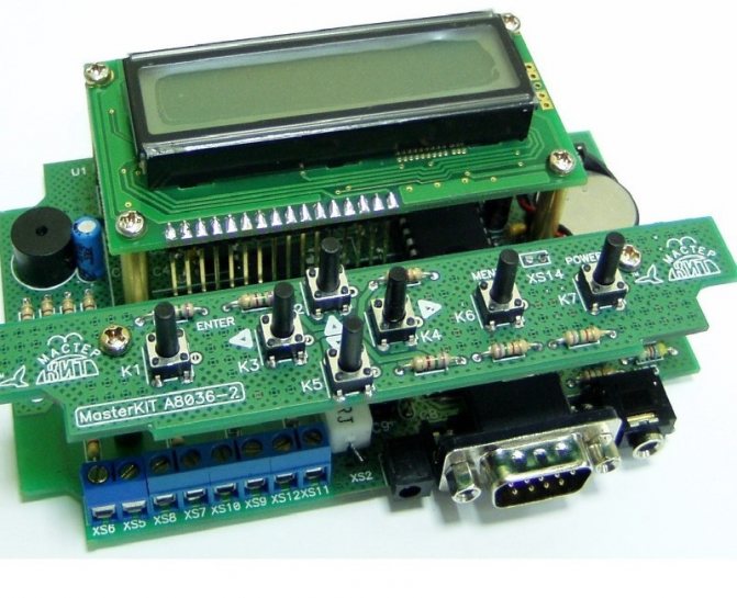
Program lines and program for NM8036. Timer-thermostat NM8036, of course, is not a bad thing, but without a person it is still just a piece of hardware. I am talking about the fact that for the normal control of heating in a private house, a program is needed, drawn up in accordance with the equipment that is used. Where to begin? Let's get acquainted with the basic principles of programming this piece of hardware. As you know from the description, only 32 commands (instructions) can be placed in the controller. Not enough, of course, but this drawback is to some extent compensated by the fact that these commands are quite functional, that is, they initially contain a certain set of conditions.
Literally every instruction command allows you to make a choice:
- command type;
- start and end times;
- period of validity;
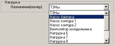
- loads;
- type of input sensor;
- sensor numbers (names);
- upper and lower thresholds of values (hysteresis);
- interaction logic.
Agree, Master, a rather extensive list and not entirely incomprehensible to the first inexperienced glance. That is why we will now go over all these points in more detail, after which, I hope, everything will not be so difficult. Just read it carefully, delve into it.
Command type. There are four of them, except for the "Disabled" type: Timer, Heating, Cooling, Alarm. Regarding the last of them, the Alarm Clock, we can safely say: hardly anyone has used it. Although, maybe someone has put this device on the wall at the head. But I'd rather use a cell phone ...
Actually, we are interested in three types: The timer allows you to turn on and off the selected load at a specific time and a specific day. Heating will turn on the load when the temperature drops to the set values, and Cooling will turn on when the temperature is exceeded.
Start and End Times and Validity Period. The choice of these values is possible for any type of commands from the three interesting to us. Here is the Start date and time and Stop date and time. This choice interacts closely with the Period of validity. How?
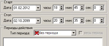
If no Period is selected (or "No Period" is selected), the selected time and date values are taken literally. That is, the load will work from the start time to the stop time and date until October 2, 2099. All the time, without turning off. And how to make the load turn on every day at the selected time, and turn off at another?
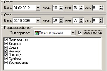
For such a logic of work, it is necessary to set the Validity Period. Any. In particular, in the example above, the period By days of the week is selected and all days are indicated. Now every day the load will be switched on during the start and off during the stop. And this will continue again until 2099.
Note: when choosing the command types Heating and Cooling, the result, along with the selected time and period of action, is also influenced by the choice of temperature values.
Load selection. It hardly makes sense to explain that this is the choice of the load on which the team acts. However, I will note again how convenient it is to make such a choice (as well as the choice of sensors) when there are assigned names. I deliberately do not show how the programming of the NM8036 unit is done from the keyboard of the unit itself, since I myself have not done this and I think it is much more convenient to do this using the Advanced Manager (I will talk about it in the next part).
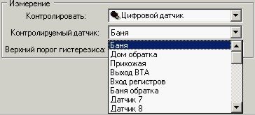
Sensors. This block of the program provides the ability to select sensors and their values. The sequence of actions is quite logical: select the type of sensor, select the sensor itself from the list and set the required values.
Sensor type. There are three options: digital (temperature sensors), analog (these are the controller's ADC inputs) and Comparison of two sensors (temperature sensors). First, let's choose Digital.
Digital gauge. From the presented list of sensor names, select the desired one.
Hysteresis. And be careful here, Master. Turning on and off the load are actions that are performed by the system at different temperatures. Do not set the same temperature values for the upper and lower thresholds, this does not correspond to the logic of the controller. The thresholds can be very close, for example, 22.12 degrees and 22.13 degrees, but they must be different.
Hysteresis is the difference between on and off temperatures. Moreover, we have two types of commands: Heating and Cooling. So, if Heating is installed, the load will always be turned on in the green zone (below the lower threshold). In the yellow zone, the load can be turned on and off, it all depends on the direction. If the actual temperature rises, the load will be turned on to the upper threshold (25 degrees). When it is reached, the load is turned off and it can be turned on only when the temperature drops to the lower threshold. Above the upper threshold, the load will not turn on under any conditions.
It is a different matter if the command type is Cooling.Here the load will always be on when the temperature is above the upper threshold (green zone). The load is disconnected at the temperature of the lower threshold (24 degrees), and switching on: at the temperature of the upper threshold (25 degrees). Thus, the temperature is maintained between values from 24 to 25 degrees with both types of commands.
Selecting an analog sensor. Here, as well as when choosing a digital sensor, it is necessary to set the enable and disable hysteresis.
The program presents two types of hysteresis setting, ADC and Physics. You can type values in any line, in another, the corresponding values will be automatically calculated. Read more about the presentation of this data in the second part on ADC inputs.
It should also be remembered that the logic of the load will also correspond to the type of command: Heating or Cooling. It doesn't matter what we measure here: temperature, pressure, kilograms, kilometers or volts ...
Comparison of two sensors. This function is not available in firmware versions below 1.95. There is also a command type dependency. In the given example, during Heating, the load will be switched on when the sensor "Return home" is "colder" than "Output BTA". If the Cooling type is selected, the situation will be reversed.
Interaction logic. In many cases, this function is in demand, since sometimes it is impossible to compose a program in which several conditions must be taken into account. For me, for example, the operation of the pump in the house should depend not only on the temperature in the hallway, but also on the return temperature of the house and on the position of the "Boiler" switch. That is, three sensors must act on the same load. In general, there can be a variety of situations in the management of heating of a private house.
First, let's figure it out, Master, with this logic. Let's agree right away that the disconnected position of the load is zero (0), and the connected one is one (1). That is, any command from 32 can give us as a result only these 2 states: 0 or 1 (disabled and enabled). All conditions in this command (time, date, period, state of sensors) were met - 1 was issued (load is on), and if at least one of the listed conditions is not met, 0 is issued (load is off).
Now let's take two teams. For the same load (I pay special attention to this). Two commands that act on the same load, but check different sensors, or set different times, or generally different types: one Heating, and the other Cooling or Timer. It doesn't matter, but the main thing is that each of them produces its own result: 0 or 1. But there is only one load! Whom should she listen to, how to behave? Will it turn on or not turn on?
This is where the interaction logic comes into play. There are two options here: the "OR" option and the "AND" option. With the "OR" option, the load will turn on if at least one command issued 1. That OR the other is not important, but if at least one gave the go-ahead, the load is turned on.
With the option "I" it is different. Here, for the load to work, two units are needed. One and the other. If at least one of the teams did not give the go-ahead, the load will not turn on.
And if there are not two teams, but three? And if four? Never mind, the logic remains the same. The main thing to understand and remember is that the interaction logic is set to interact with the previous command for the same load. Well, here, we got acquainted with the principles of programming the NM8036 in the control of heating a private house. But the conversation is not over yet, we will still give examples, get acquainted with various tricks.
The logic of the operation of my system, as I already mentioned, provides for two modes, in one of which the boiler is in operation, and in the other, the air temperature is regulated. The switch "Boiler" is engaged in switching the mode.
The name of this switch, as it may seem, does not correspond to its logic. Why? Because when it is on, it gives out a voltage of 0 volts, and when it is off, it gives out 5 volts.This is not a necessary measure, I just put it at random during the assembly. Accordingly, I did the program, I did not want to sort it out. Further.
The program contains 5 loads that it controls:
1. Bypass pump. 2. Pump of the circuit to the house. 3. Heating elements of an electric boiler. 4. Warning signal. 5. Alarm signal.
Controlled temperature sensors: 1. Air temperature in the hallway. 2. Temperature at the input of the registers. 3. Temperature in the return pipe of the heating circuit.
In general, one mode switch, five loads and 3 temperature sensors. All this must be linked in some way in a certain logic into one whole: the control program. Getting started!
Initially, we will determine the values by which we will determine the position of the mode switch. There should be two meanings. One of them should be above average, the other below. I accepted the upper hysteresis threshold of 2.7 volts, and the lower one - 2.0 volts. It could have been further from the middle, say, 3.5 volts and 1.5, but, as it turned out, even with the accepted values, the program clearly determines the position of the switch.
In simpler terms, the program now knows that if the voltage is below 2 volts, then the "Boiler operation" mode is on. If the input voltage is higher than 2.7 volts, this is the "Loop Operation" mode.
This circumstance already allows us to control one of the loads: Bypass pump. When the "Boiler operation" mode is on, this pump must be turned on and pump water, but in the "Circuit operation" mode, this pump is not needed. There are no other conditions for this load.
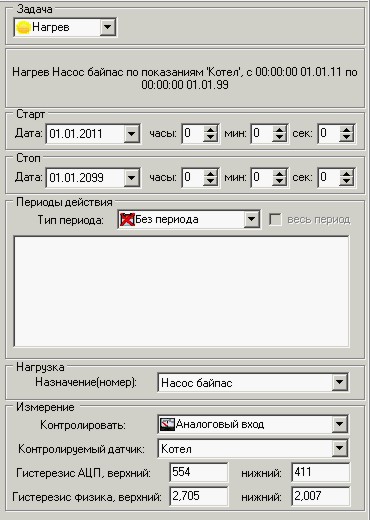
And so, the first line. We set the start-stop until 2099, let it always work as long as the supply voltage is present. The type of period is not selectable, no periodicity in time is required here. The load is indicated, the sensor is indicated, the hysteresis values are determined.
But why exactly Heating? But because with this choice, the load will always be on, as long as the input voltage is below the upper hysteresis threshold (that is, below 2.7 volts). I explained these states in more detail above.
Now, thanks to this line of the program, the bypass pump will be turned on all the time while the "Boiler operation" mode is switched on with the toggle switch. Do you, Master, have a question like: Maybe it's better to just turn on the pump with a toggle switch? After all, no difference, it's still a toggle switch!
If it arises, I will answer like this: And this toggle switch of mine not only turns on the bypass pump. Thanks to the operation of this toggle switch, other tasks are performed, which are discussed below.
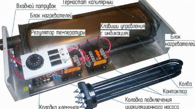
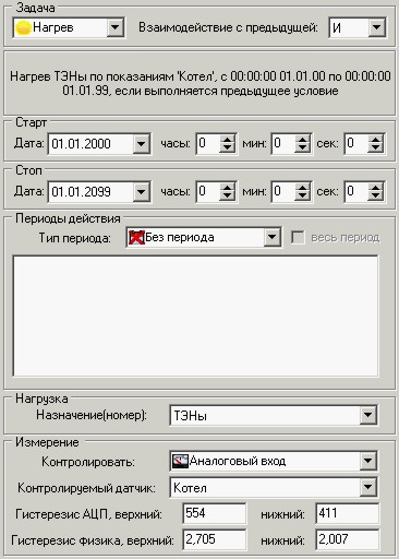
Next, we will deal with the Heating of registers. For this I have an electric boiler installed. The heating elements in it should turn on when the temperature at the inlet of the registers is below 40 degrees. But there is one more condition: they should be switched on only in the "Boiler operation" mode.
About the temperature: I have already spoken about the error of the temperature sensors attached to the pipe with an adhesive plaster. Therefore, we will take this error into account and set the hysteresis limits somewhat lower. How much - I determined it empirically.
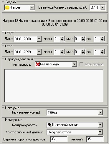
So, for this load (heating elements), two conditions must be met. Let's start with the first one, with the temperature, and set the values for the first row of the heating element load. I have the same start-stop and period type in all lines, so I won't mention them anymore.
For the rest, select the Heating task, heating element load, control the register input sensor and set the hysteresis 36-35. With such settings, the heating elements will turn on at a temperature of 35 and below, and they will turn off when they reach 36 degrees (in nature, I have 41 degrees).
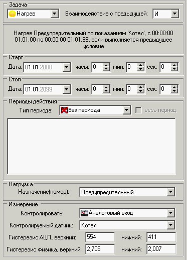
Now it is necessary to somehow fulfill one more condition for this load (heating elements): the "Boiler operation" mode. Here it is easier for us, we have already fulfilled such a condition in the very first line for the bypass pump. We put everything exactly the same here, in the third program line in a row and in the second in a row for the heating element load.
In contrast to that line, we indicate, of course, the load of the heating element and (ATTENTION!) In the upper right corner we make the choice of the logic of interaction I. If you forgot a little, Master, I refer you again above, where the logic of interaction is discussed in more detail.
Thus, the load of the heating element will now turn on only when the temperature at the input of the registers is below 40 degrees and only when the "Boiler operation" mode is on.
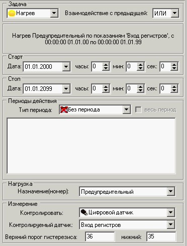
And now it's time to think about the alarm. In particular, when the heating elements are turned on, short rare tickers should sound. Here, in theory, it would be possible to simply connect the signaling device to the heating elements, and all business. The only question is: how? After all, the heating element load relay switches 220 volts of change, and 12 volts of constant must go to the warning signaling. So, you have to program a separate load: Warning.
So we will do it. Everything is exactly the same as for the heating element load, there are also two lines, but indicate the load in them: Warning. On the left we see the first line ...
And here is the second line for the Warning signal.
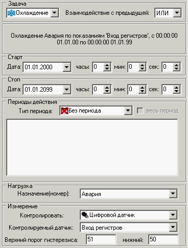
We will immediately make an alarm signal, that is, a temperature rise signal at the input of the registers. And here, too, two program lines are required, since it is necessary to control the temperature at the register input and observe the condition of the "Boiler operation" mode.
Almost everything is the same as for the Warning signal. Almost, because we indicate the load Alarm, hysteresis 51-50 and (ATTENTION!) The task we select Cooling. With this arrangement, the load Alarm will turn on and will work when the temperature at the input of the registers is 51 and higher according to the sensor. In nature, I have it 58 and above.
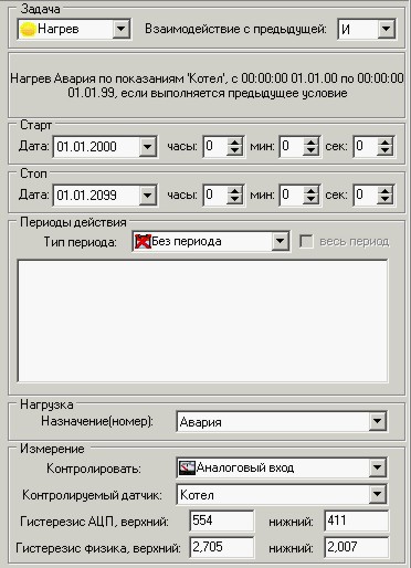
And in the second line to the load “Emergency” we fasten the “Boiler operation” mode. Interaction logic AND!
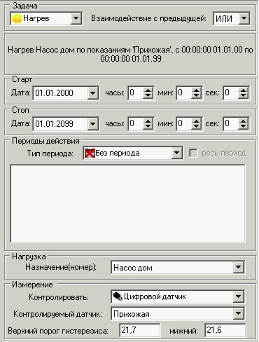
And we finally arrived at the adjustment of the air temperature in the hallway. Here we will not manage with one line, and we will not do with two. Here I have three conditions: the temperature in the hallway, the temperature in the return flow of the circuit and ... the mode "Circuit operation" Not a boiler, but a heating circuit.
In theory, it’s not so difficult here, even though it’s three lines. The first line is to control the temperature in the hallway. Task Heating, load Pump house, hysteresis 21.7-21.6.
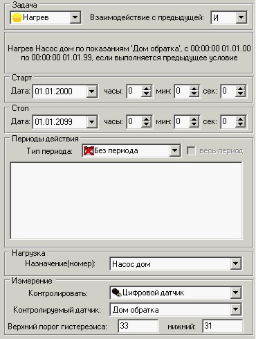
The second line is the important line. This is the temperature condition in the return pipe of the circuit. The pump must stop pumping hot water if its return temperature has exceeded 33 degrees.
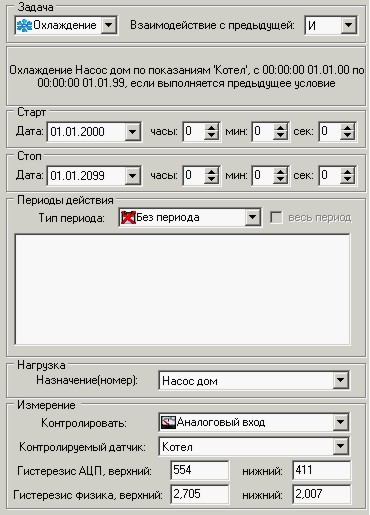
And this is the third line for the pump house load, and the last line in my heating control program. Pay attention, Master, here the Cooling task is selected for the toggle switch. I think you all understand why this is so.
Of course, not all of the features of the NM8036 are used in my heating control program. There is also a comparison of two temperature sensors, which I did not use out of need.
I would also like to say a few more words about the logic of interaction. The instructions say that for each program line, the logic of interaction with the previous line is determined. But I would correct here. A bit wrong. More correct: the logic of interaction with the result of the previous lines. What does it mean?
But look: we have, say, 5 lines of program for the same load:
1.line 1 (OR) 2.line 2 (AND) 3.line 3 (AND) 4.line 4 (OR) 5.line 5 (AND)
How can you determine what the result will be? Let's start at the top. In the first line, the logic is not counted because there are no previous lines for this load. However, if you put the AND logic in the first line, then this line will never be executed for you (it will give 0).
The second line works with the first according to the AND logic. That is, the first should return 1, and the second - 1. Two ones in the AND logic will give one at the output: 1. If at least one of the conditions is not met, the output of the second line will be zero ( 0).
The third line works ... not with the second! She works WITH RESULT from the second. It works with this result according to the logic AND, and gives its result, 0 or 1.
Fourth line.Confused yet? Pay attention, it works with the RESULT of line 3 according to the OR logic (any 1 on the input will give 1 on the output).
And finally, the fifth line. If we are not confused and we know exactly the result after the fourth line, then we can well determine the result after the fifth. Logic AND: for 1, the output must be two ones at the input. And if after the fifth line we get 1 at the output, our load will turn on. 0 - will not turn on.
To be continued…
Place of installation
As you know, the air temperature in a room with traditional heating systems on radiators warms up unevenly. It is lower near the floor, higher under the ceiling.
Based on the presence of a built-in temperature sensor in the thermostats, their installation height is regulated.
Such thermostats should be placed at a height of 1.2-1.5 m from the floor level and as far as possible from heating sources, including protected from direct sunlight.
It is also not recommended to put thermostats in the hallway or in the kitchen.
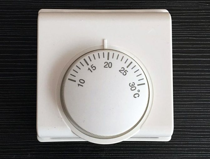
Mechanical or electronic thermostat
By the way, for a gas boiler, you can use another simpler type of regulator, which does not even have to be supplied with a voltage of 220V. For example, Termec Emmeti mechanical thermostat or other similar models.
Here is the "usual" Termec wiring diagram.
You only need to use normally closed contacts 1 and 3, completely eliminating the 220V change (L and N).
The built-in sensor will open and close the internal contact when the temperature in the room changes. He does not need any food. In this case, the entire logic of the heating operation is similar to that discussed earlier.
Just remember that almost all mechanical models have a very large hysteresis. You cannot create a comfortable room temperature with their help.
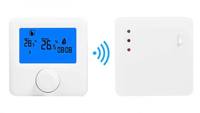
Therefore, whenever possible, choose electronic devices with a WiFi connection. Fortunately, in our time, the Chinese can find very decent and inexpensive options.
For example, such as this one (thousands of satisfied customers and positive reviews). More details
Some models have contacts labeled NO (normally open), NC (normally closed), and COM (common). Someone advises to connect through them, namely through NC and COM.
However, be careful, the thermostat is the thermostat, and always read the instructions. Through them, an alternating voltage of 220V can also be supplied, and thereby you start a phase on the control board where you do not need it.
Here's a prime example of these multifunctional Fluoreon and Beok controls.
On multifunctional devices, the room temperature is also determined using the built-in temperature sensor.
However, they have terminals on the body for connecting and external (Sensor). It is most often used for underfloor heating.