Pros of the Valtec system
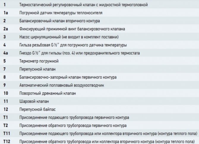
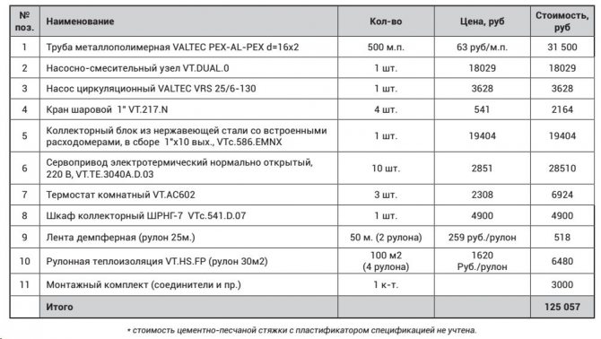
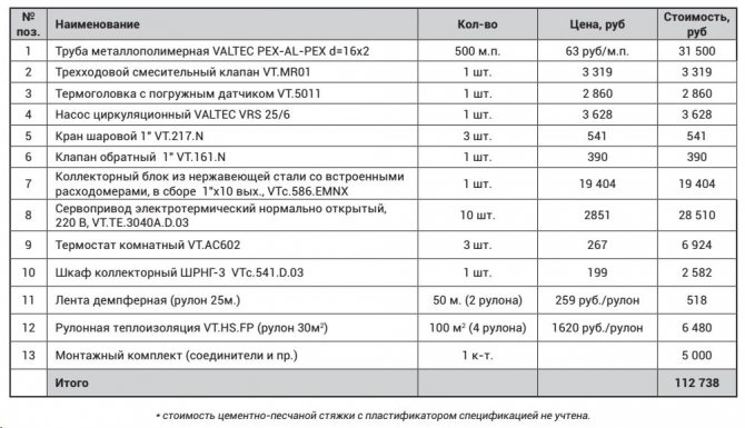
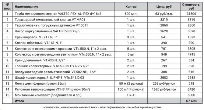
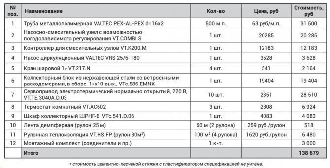
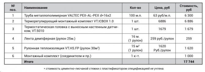
Valtec mixing unit specification for underfloor heating
Before starting installation and selecting a mixing unit for a Valtec underfloor heating, it is necessary to analyze the advantages of this type of water circuit.
- Thanks to high-quality materials, durable fasteners, reliable operation is ensured.
- Modularly designed components fit exactly together, eliminating the risk of leaks.
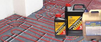
- The manufacturer has provided for the production of related materials required for thermal and waterproofing equipment.
Installation systems
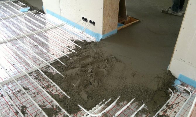
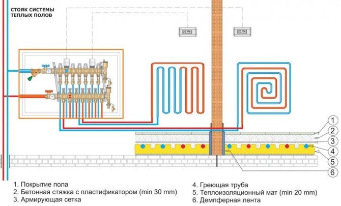
There are various ways to install a water-heated floor. Often, a heat-insulating material is installed on a concrete base, on top of which heating elements are mounted. Rolled substrate VT.HS.FP is made of 2 materials - foamed polyethylene and a metallized layer located on the front of the product.
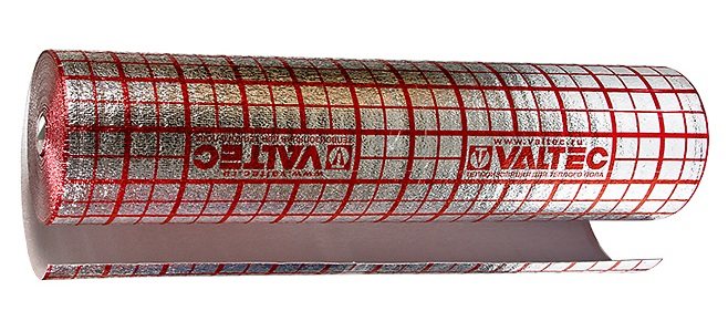
Due to the reflectivity of the top coating, the efficiency of the water-heated floor is increased. For ease of installation, markings are applied to the surface of the material, along which pipes can be easily installed. A thin underlay will not increase the overall floor height. But its characteristics contribute to greater heat transfer of heating.
Calculation instructions
In order to correctly develop a project for laying a warm floor, a preliminary calculation of the main indicators will be required, focusing on their average values.
Do-it-yourself installation of a water-heated floor
Various factors have to be taken into account, including the role of the water floor as the main type of heating or its use as an additional source of heat. Since a detailed calculation for self-execution is a complex process, in practice, averaged parameters are used.
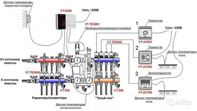
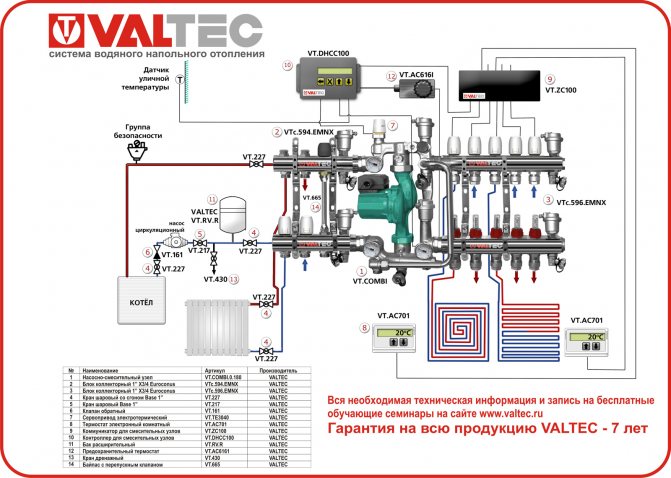
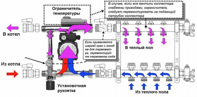
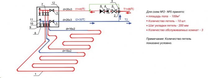
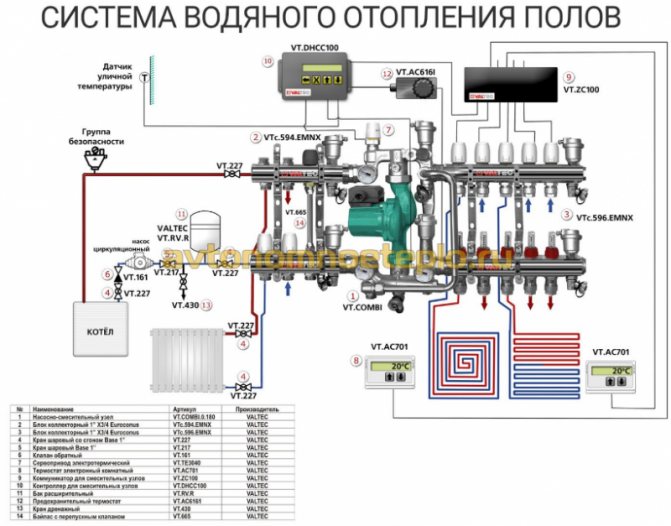
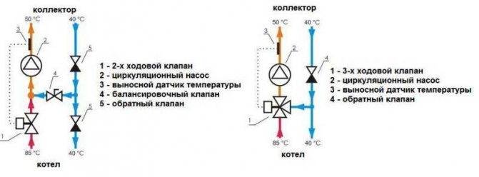
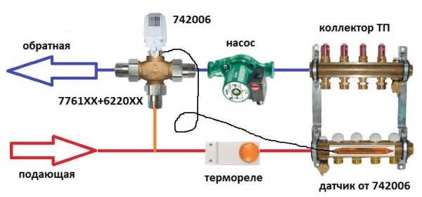
Valtec mixing set connection diagram
- The rated power has a range of 90 - 150 W / m2. Higher values are selected for rooms with high humidity levels.
- When calculating the laying step, it is necessary to focus on the range of 15–30 cm. With this indicator, the specific heating power is in inverse proportional relationship. That is, the larger the step, the less power.

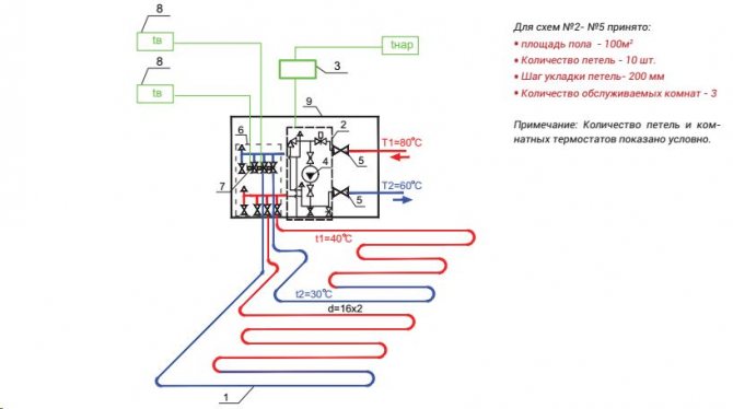
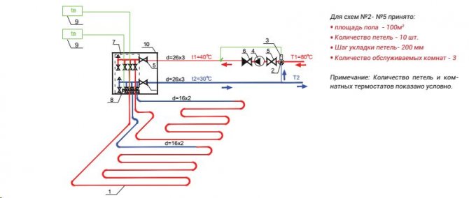
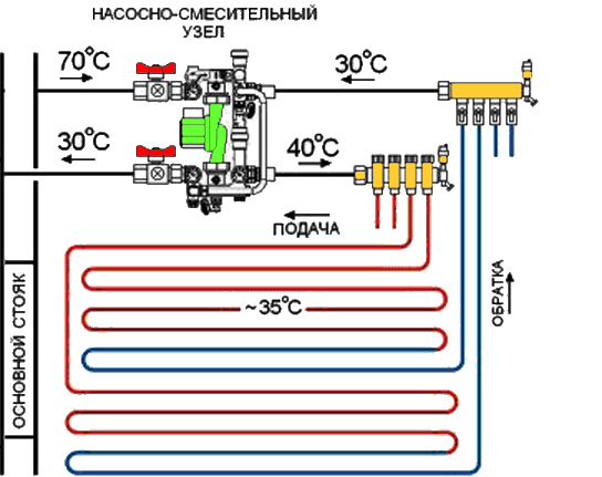
Thermal-mechanical diagram of the pump-mixing unit - Despite the fact that with a large diameter of pipes, a larger amount of coolant passes through them, the thickness of the screed serves as a limiter for this indicator, which is not recommended too large so as not to create excessive load on the floor. Therefore, Valtec pipes made of modern cross-linked polyethylene with an anti-diffusion coating, with a diameter of 16 to 20 mm, are taken into account, and Valtec press fittings act as connecting parts.
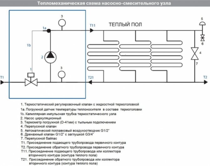
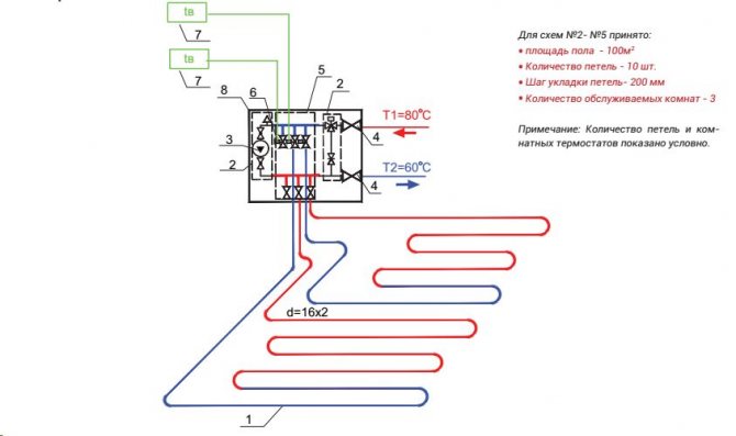
After determining the key parameters, a scheme can be developed on which the most rational pipe laying is determined on an exact scale. After that, their total length is calculated. At the same time, it is considering where the pumping and mixing unit and control elements will be located.
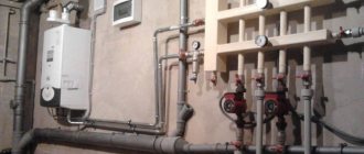
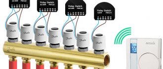
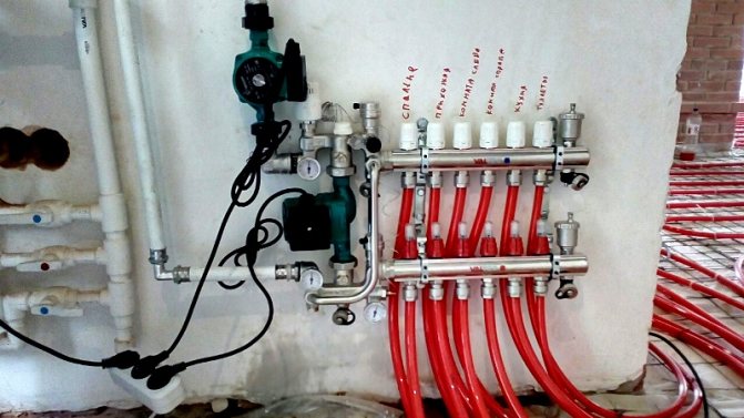
Two pumping and mixing units for underfloor heating in one heating system.
I got two floor heating mixers in one heating system.
I made one immediately at the first stage of the repair and installed it temporarily.
While this mixer was running one branch of the warm floor. Then he intended to move it at the end of the renovation in other rooms. I laid the pipes in the floor in order to connect this branch to the mixer in a new place.
But nothing is more permanent than temporary.
And in a new place I installed another one of the same mixer.
Someday I will remove the first mixing unit - the collector of the second mixing unit has fittings for connecting this branch and pipes have already been laid.
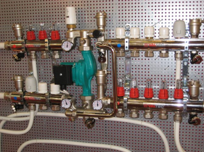
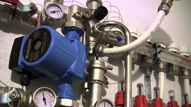
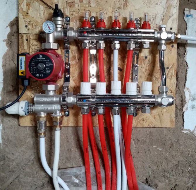
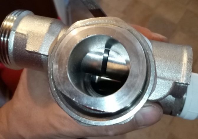
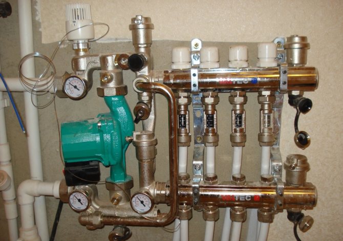
Please note that the mixer in the first photo is not able to provide a supply temperature of the coolant greater than 25 degrees at the temperature set on the boiler, 50 degrees. The photo shows the coolant temperature of 30 degrees, which is reached at a boiler temperature of 60 degrees and the thermostatic head of the mixer is set at 40 degrees.
The photo shows a coolant temperature of 30 degrees, which is reached at a boiler temperature of 60 degrees and the thermostatic head of the mixer is set at 40 degrees.
This is just understandable with such a connection.
The paradox is that this (25 degrees) is enough to heat the room relatively quickly by a couple of degrees, maintaining the set temperature.
Key features of the mixing unit
In order for the installed water circuit to function effectively, it is necessary to correctly calculate the entire system and correctly install the Valtec underfloor mixing unit in accordance with the provisions that are reflected in the instructions attached to the kit.
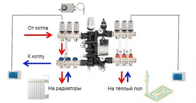
Connection diagram of the mixing unit to different types of heating
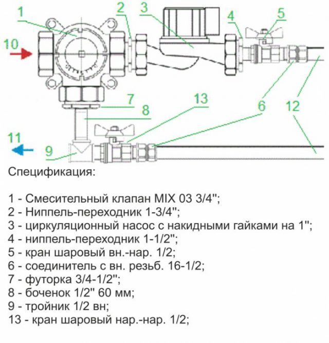
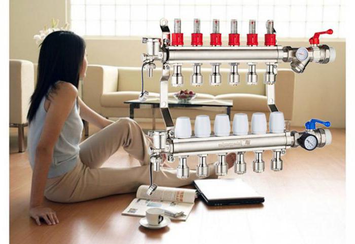
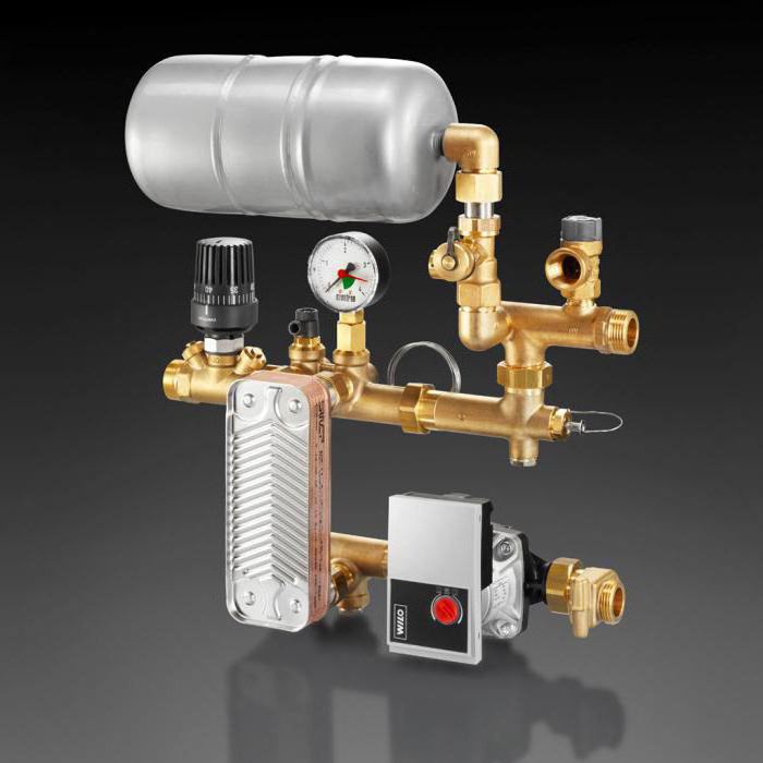
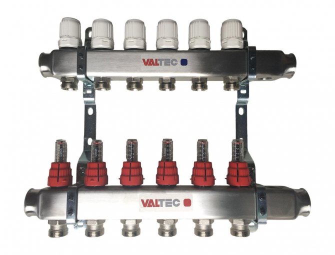
Pump-mixing unit parameters:
- the cross-section of pipes is ¾ ", collectors - 1";
- there are 12 branch pipes in the structure;
- the pumping system is 18 cm long;
- the temperature regime of heated water in the system is maintained up to 90 ° С;
- maximum pressure value - 10 bar;
- throughput - 2.75 m3 / h.
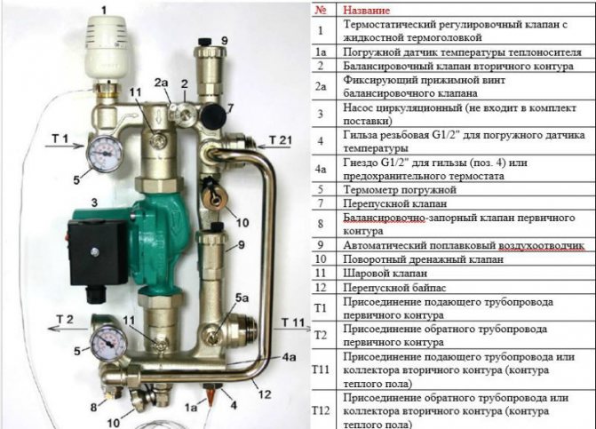
Valtec pump and mixing unit specification
The pipes have an external thread with a Eurocone connection.
Pump and mixing unit for underfloor heating
Installation
Valtec underfloor heating, as we already know, uses hot water as a heat source. The work of this system is carried out as follows: a pipe is installed along the perimeter of the floor surface through which hot water will circulate. Water can be heated using central heating or using a gas boiler (but the latter is preferable, since the operation of the floor heating system will not depend on the water temperature, on the pressure in the network or on seasonal water outages in the central heating network).
In order for the warm floor to fully cope with its work, it is necessary to remember several points: firstly, thermal insulation is imperative; secondly, you need to select the most heat-conducting materials; thirdly, it is necessary to lay the pipe in a cement screed so as not to damage the pipe and increase the surface area that we will heat.
Functionality
The main purpose of the pumping and mixing unit is to stabilize the temperature of the coolant when it enters the water circuit by using it to mix water from the return line. Thus, the underfloor heating works optimally without overheating.
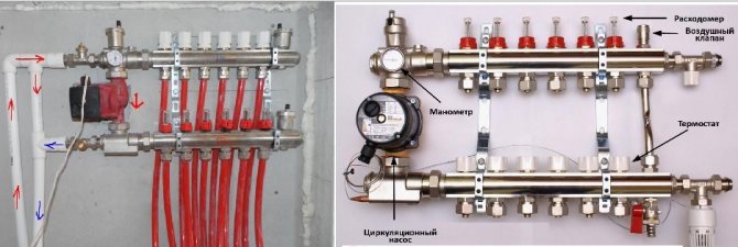
The following service elements are included in the Combi assembly:
- drain valves;
- air vents;
- thermometers.
How the Combi unit works
The following organs are used to adjust the knot:
It is permissible to connect an unlimited number of underfloor heating branches to the VALTEC COMBIMIX node with a total power of no more than 20 kW
- a balancing valve on the secondary circuit, which provides mixing in the required proportion of heat carriers from the supply and return pipelines to ensure the specified temperature;
- balancing and shut-off valve on the primary circuit, responsible for supplying the required amount of hot water to the unit. It allows you to completely shut off the flow, if necessary;
- bypass valve to open an additional bypass to ensure pump operation when all control valves are closed.
The connection diagram is designed taking into account the possibility of connecting the required number of floor heating branches to the pumping and mixing unit with a total water consumption not exceeding 1.7 m3 / h. The calculation shows that a similar value of the coolant flow rate at a temperature difference of 5 ° C corresponds to a power of 10 kW.
If several branches are connected to the mixing unit, it is advisable to select manifold blocks from the Valtec line with the designation VTc.594, as well as VTc.596.
Valtec water heat-insulated floor
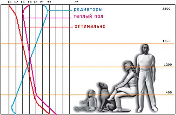
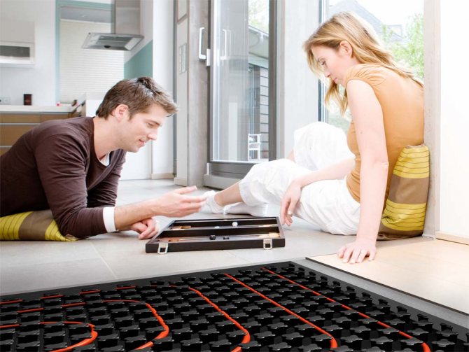
The well-known saying “Keep your feet warm and your head cold” is the best description of the “warm floor” heating system, which is so popular today. Indeed, in comparison with radiator heating, underfloor heating creates the most comfortable conditions for a person. The heat is distributed evenly, which helps to maintain an optimal indoor climate. In addition, the use of underfloor heating allows you to save energy and free living space from bulky heating devices, which will make the most efficient use of the area and not complicate the task when choosing a room design.
To be able to implement the underfloor heating system, it is necessary that the room has a reserve in height to accommodate the "threshold" of the warm floor. The minimum required height of the underfloor heating structure is 85 mm (excluding the floor covering).
Accessories for the installation of a warm floor
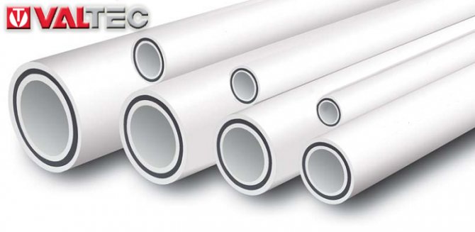
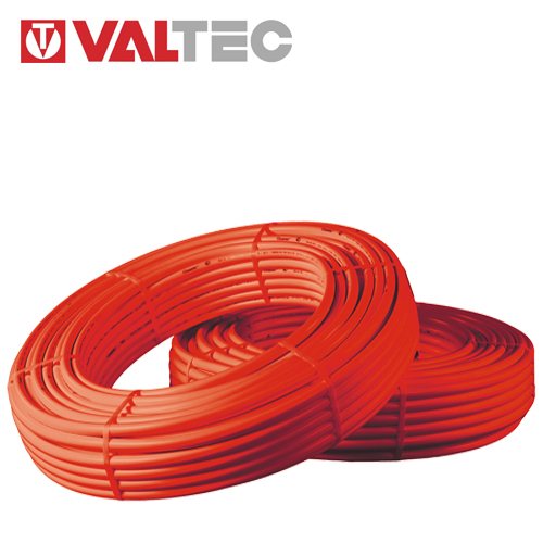
1. Trumpet
In most cases, XLPE pipe is used.
XLPE pipes are actively used in various fields. Their advantages are:
-resistance to high temperatures, allowing the use of pipes in hot water supply and heating; - elasticity, elasticity, the so-called molecular memory (the ability to restore its shape after mechanical stress) of the material. In addition to the fact that pipes made of cross-linked polyethylene can be bent without heating (up to certain radii) and a special tool, they can withstand several freezing cycles of the transported liquid, do not propagate (on the contrary, absorb) noise and vibrations, and absorb hydraulic shocks; - chemical and electrical inertness, resistance to aggressive media (and hence, non-susceptibility to corrosion); -low roughness of the inner surface (this reduces hydraulic resistance, excludes overgrowth of channels); -higher than ordinary polyethylene, resistance to ultraviolet rays; -hygienic (pipe material does not emit harmful substances into the flow in the operating temperature range); -resistance to abrasive wear and aging; - the lightness of pipes, the possibility of purchasing them in coils of great length; - simplicity and manufacturability of installation.
The disadvantages of pipes made of PE-X include a high coefficient of thermal linear expansion (0.15-0.20 mm / m x ° C); sensitivity to prolonged exposure to sunlight (there is no contradiction with what was said about this above); inability to maintain the bend shape given during installation (the pipe must be secured using clamps or clamps).
Currently, 3 methods are used for crosslinking polyethylene:
-PE-Xa (high pressure heating in the presence of peroxides). The peroxide method (PEX-a) is a chemical method for crosslinking polyethylene and consists in crosslinking with organic peroxides and hydroperoxides. The pipeline obtained with this method has a degree of crosslinking of about 75%.
-PE-Xb (exposure to chemicals, one of which is silane). The silane method (PEX-b) is also chemical. When crosslinking in this way, organosilanides are used. The minimum stitching ratio by this method is limited to 65%;
-PE-Xc (electron irradiation of the finished product) - Radiation crosslinking (PEX-c) is performed using a stream of charged particles. The stitching ratio is about 60%.
Memory effect
Shape memory is very useful for editing.If during the installation of the pipeline a break, squeezing or other deformation is formed, then it can be easily eliminated by heating the pipeline to a temperature of 100-120 ° C. In addition, when connecting a PEX pipeline to a fitting, deformations also occur in the grooves of the fitting (Fig. 2). When the coolant is supplied and the pipeline warms up, restoring forces arise in these places. Due to these efforts, the pipeline fits the fitting more tightly, which increases the reliability of the connection.
For modern heating systems, it is important that oxygen does not enter the coolant. One of the ways of its penetration is diffusion through the walls of plastic pipes. Therefore, PEX pipes for heating are additionally equipped with a polymer gas-tight layer based on ethylene vinyl alcohol (EVOH).
VALTEC offers PEX-EVOH polyethylene pipes made of cross-linked polyethylene PE-Xb. The outside of the pipe is coated with an EVOH anti-diffusion layer with a thickness of 50 microns. The outer and inner layers of the pipe are bonded to each other using Plexar PX 3216 elastic glue.
In the VALTEC PEX-EVOH pipe, the anti-diffusion layer is made from the outside, i.e. the pipe has a three-layer structure: PEX-glue-EVOH. There are also five-layer ones on the market (PEX-glue-EVOH-glue-PEX)
It is a misconception that the outer layer of EVOH in a 3-layer construction is prone to abrasion. The hardness of the EVOH layer is significantly higher than that of the PEX layer, so if properly handled, damage to the outer layer is unlikely.
At a pressure of 6 bar, the operating temperature for them is limited to 80 ° C (not exceeding these parameters is a condition for 50 years of pipe operation). For a short time, let us heat the heat carrier up to 95 ° C.
The choice of the range of the degree of crosslinking of polyethylene of 68-70% for VALTEC PEX-EVOH pipelines is due to the optimal ratio of the strength characteristics of the pipeline and its flexibility. For example, a VALTEC PEX-pipe can be manually bent at room temperature by a radius equal to five diameters of the pipe, and when using a pipe bender or conductor - by a radius equal to three diameters. Pipelines with more than 70% crosslinking will have a manual bend radius of at least seven diameters. A greater bend of the pipeline with this degree of crosslinking can only be achieved using a building hair dryer.
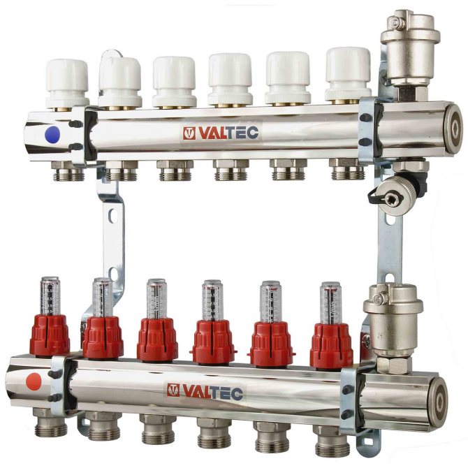
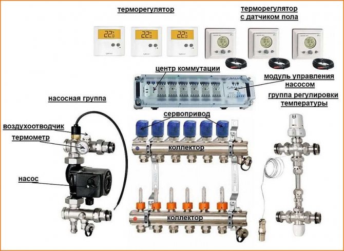
2. Collector group
The functions of the collector for underfloor heating are the distribution of the coolant in the circuits of the system, and if appropriate equipment is available, hydraulic balancing of the loops, shutting off the flows, removing air from the working fluid, draining the coolant. VALTEC manifolds are made of high quality sanitary brass CW617N with nickel plating or stainless steel. The manifold blocks assembled on their basis are equipped with the necessary piping elements - shut-off, adjustment valves, automatic air vents, drain valves. The block connections are sealed with EPDM rings, no other sealants are required. The standard for connecting pipe loops is Eurocone. The set includes brackets for wall (or in a control cabinet) collector mounting. The use of ready-made VALTEC modules - manifold blocks, pumping and mixing units - is the simplest solution to the problems of creating water floor heating, saving time, money, space, minimizing the risks of design and installation errors.
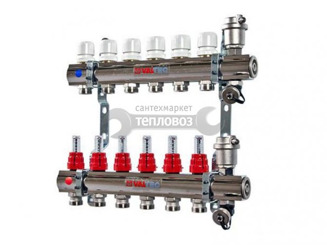
3. Pump and mixing unit
The VALTEC COMBIMIX pump-mixing unit (VT.COMBI) is designed to maintain the specified coolant temperature in the secondary circuit (due to mixing from the return line). With this unit it is also possible to hydraulically link the existing high-temperature heating system and the low-temperature underfloor heating circuit. In addition to the main controls, the unit also includes all the necessary set of service elements: an air vent and a drain valve, which simplify the maintenance of the system as a whole.Thermometers allow you to easily monitor the operation of the unit without the use of additional devices and tools. It is permissible to connect an unlimited number of underfloor heating branches to the VALTEC COMBIMIX node with a total power of no more than 20 kW
System setup is described by the manufacturer. In order to get acquainted, follow the link https://valtec.ru/document/article/combinix-balancing.html
INSTALLATION
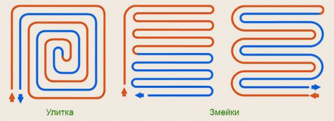
Methods for laying out floor heating loops around the room
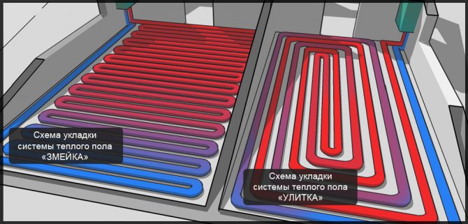
Snake in rooms of irregular shape, or with a special purpose. With this configuration, it is necessary to lay the supply pipe against the outer walls, so as not to significantly increase the temperature difference between the floor surface and the environment, which is typical for this type of installation.
A snail, used in most cases, as it achieves a more even distribution of temperatures (the supply pipe is laid next to the return pipe), which simplifies the laying work, since it only requires two 180 ° turns: thanks to the parallel laying of the pipes.
Compared with the "snake" layout, the second option gives 10 = 15% savings in the number of pipes and significantly wins in terms of hydraulic characteristics due to the small number of bends by 180 degrees
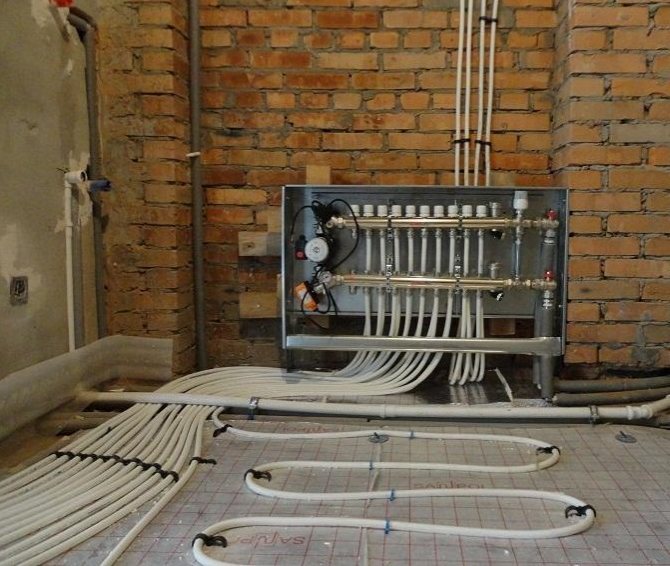
1-Installation of the manifold cabinet, manifold and pump-mixing unit
2- Floor preparation
The surface must be free of irregularities
Damping tape is laid along the perimeter of the walls to reduce heat loss through the walls and compensate for deformations
Polystyrene foam is laid for thermal insulation (extrusion PPP is laid in the case when the screed is an element of the foundation structure
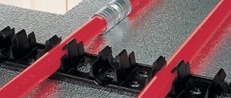
Thanks to the "bosses", the pipe is laid with a reliable fixation, which allows it to not be fixed additionally.
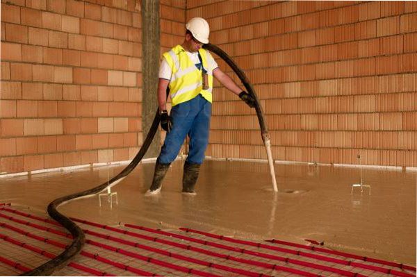
With the help of Eurocone couplings, the pipes are connected to the collector, and the insulation avoids the formation of condensation and protects the pipe from the effects of concrete. To check the reliability of the connections made, a pressure test is carried out (IMPORTANT! If the system will not be started in winter, then it is necessary to drain the water or pour in an anti-freeze liquid during the pressure test).
After these steps, the screed is poured, but it is important to leave the pipes under pressure so that the concrete does not squeeze them. Concrete gains its strength in 28 days, while it will gain 75% strength in 5 days.
Valtec offers equipment with which you can create comfortable conditions, while you should not be afraid of difficulties in installing and configuring equipment, because all materials are available for review. You or the person who will be engaged in the installation will be able to calculate, install and commission everything without any problems, and later you will enjoy the comfort in your home.

Installation Algorithm
After the preliminary calculation of all the components is completed, the installation of the warm floor begins directly, which involves the passage of several stages.
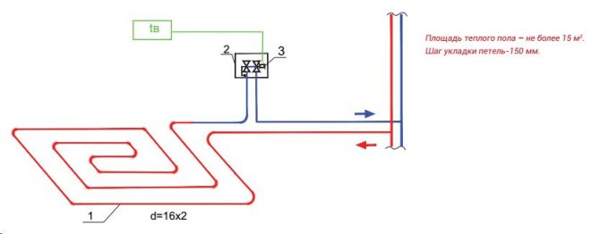
Floor heating scheme
- Installation at a pre-selected location of the manifold cabinet. It houses a module consisting of a manifold block and a pump-mixing unit with ball valves, through which the connection to the high-temperature circuit will be made.
- Preparation of the floor plane. If there are significant irregularities, measures are taken to eliminate them. The most effective option is a rough screed.
Connection diagram of the pumping and mixing unit to the warm floor - Fixation along the perimeter of the damper tape, which serves as an element that compensates for the possible expansion of the screed that occurs when it is heated. It is attached to the walls so that after finishing there is a surplus, which is cut off before installing the plinth.
- Equipment for thermal insulation by laying on the leveled floor of expanded polystyrene plates with mounting bosses, under which waterproofing is laid, if necessary.
- A previously developed diagram serves as a guide for the subsequent layout of pipes.
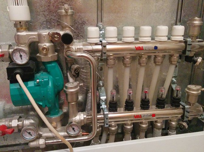
How to assemble a collector?
The Valtec distribution block is assembled.The hot pipe already has flow meters installed. There are thermal heads on the cold line, but the product may only have outputs for attaching temperature control devices. They are protected by plastic caps. The manufacturer makes it possible to choose which automation to install: a thermal head, a servo drive.
It is necessary to connect some small elements to the collector group:
- On the right, shut-off valves are connected to the tubes. The set includes 2 pcs.
- A float device is connected to the valves for air discharge.
- Drain valves are connected opposite the air vents on the lower side of the pipes.
- The ends of the comb are closed with plugs.
We recommend: What is included in the Valtek underfloor heating kit?
A circulation pump and a three-way or two-way valve are separately connected to the manifold. These devices are sold separately. They are connected to the left of the tube into which the cold coolant enters. Use brass threaded fittings.
Cold and hot circuits are removed from metal pipes that are connected to a boiler or stove. They are connected by means of a bypass at the outlet of the collector group. A circulation pump with a temperature sensor is installed between the circuits.
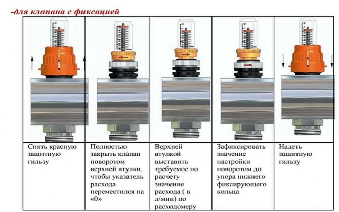
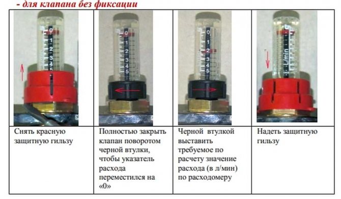
Adjustment of the rotameter is carried out when testing the heating system. The thermowell must be removed from the device. Using the red ring, the upper sleeve, set the rotameter to zero.
Then, using the same sleeve, the valve is installed on o for large rooms, on o for small rooms. To fix the parameters of the rotameter, the lower ring is turned to the right until it stops.
Return the protective cap to its original place. The flowmeter may not have a retaining ring. In this case, the filling rate of the pipeline is set without fixing. Valve function should be checked regularly.
Collectors "Valtek" for underfloor heating are installed with a liquid heating system. The coolant can be water, antifreeze, glycol fillers, which do not freeze at low temperatures. If the heating system is not used, then the coolant does not need to be drained.
The number of circuits on the distribution block is 3-12 pcs. If necessary, additional equipment can be connected to them in order to increase the flow capacity of the coolant to all rooms in the house.
The comb is fixed on the wall or placed in a manifold cabinet. The manufacturer gives a 10-year warranty for the equipment. Service centers are located in St. Petersburg, Moscow. The unit will serve for over 50 years.
If necessary, the rotameter or thermal head can be replaced without shutting down the heating system. When using a programmable thermostat, the operation of the underfloor heating control unit can be carried out through electronic gadgets.
We recommend: Features of the system "combined heating: warm floor and radiators"
YouTube responded with an error: Access Not Configured. YouTube Data API has not been used in project 268921522881 before or it is disabled. Enable it by visiting https://console.developers.google.com/apis/api/youtube.googleapis.com/overview?project=268921522881 then retry. If you enabled this API recently, wait a few minutes for the action to propagate to our systems and retry.
- Similar posts
- How to install an electric underfloor heating?
- How is the underfloor heating connected?
- Pros and cons of underfloor heating
- How to connect a warm floor?
- Underfloor heating principle
- Can laminate flooring be laid on a warm floor?
Customization
To connect the pipes to the manifolds, use a pipe cutter to cut to the desired length, a calibrator for chamfering and a compression fitting. It is difficult to carry out a detailed calculation at home, therefore, the instructions must be studied, which detail the setting of the pumping and mixing unit in a certain sequence.
- The thermal head is removed.
- For the balancing valve on the secondary side, the capacity is calculated using the formula.
Two variants of the mixing unit
kνb = kνt {[(t1 - t12) / (t11 - t12)] - 1},
where kνt - coefficient = 0.9 valve throughput;
t1 - water temperature of the primary circuit at the supply, ° С;
t11 - temperature of the secondary circuit at the coolant supply, ° С;
t12 - water temperature of the return pipeline, ° С.
The calculated kνb value must be set on the valve.
- Setting the desired mode of operation of the bypass valve at setting the maximum value of the differential pressure of 0.6 bar.
- In order for the underfloor heating to function efficiently, the required pump speed is adjusted. To do this, it is necessary to determine the value of the flow rate of the coolant in the secondary circuit system, as well as the pressure losses that appear in the circuits located after the unit.
Valtec mixing unit equipment
Consumption G2 (kg / s) is determined by the formula:
G2 = Q / [4187 • (t11 - t12)],
where Q is the total thermal power of the water circuit connected to the mixing unit, J / s;
4187 [J / (kg • ° С)] - heat capacity of water.
A special hydraulic calculation program is used to calculate the pressure loss. To determine the pump speed, which is set using the switch, according to the calculated indicators, a nomogram is used, which is in the instructions attached to the underfloor heating structure.
Connection diagram for underfloor heating circuits
- Operations are performed to adjust the balancing valve on the primary circuit.
- The temperature regulator is set to the temperature required for comfortable heating.
- A trial run of the system is in progress.
In the absence of leaks, it remains to make a concrete screed, and after it has completely hardened, lay the floor covering.
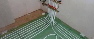
Tuning manifolds with tuning meters
Pre-setting of underfloor heating collectors is necessary and important. Even if the system has thermostats, controllers and other automation. If you entrust the adjustment to the automation, after a while all streams will be as open as possible. So before starting the system, we are setting up the collector. Adjust the flow rate on a cold system without turning on the boiler. Heating is started after setting the costs for the loops - to check the temperature.
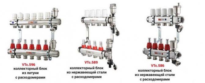
Valtec manifold with flow meters is easier to set up
What is a flow meter and its device
Flow meters are used for the initial adjustment of flows, which is easier, more accurate and faster with them. In addition, during operation, they allow you to estimate the current flow rate in relation to the one set during setup. To understand the mechanics of tuning, you need to know how the meter works and how it works. It is a hollow body with a poppet valve supported by a spring. The spring is calibrated. Its top is brought out into a transparent cone with a scale.
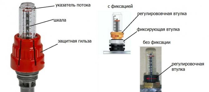
How the Valtek flowmeter works
In order to be able to navigate by the flow values and, in fact, to regulate it, a flow indicator is attached to the spring. For flow meters that are installed on the delivery, the flow indicator is installed at the top of the body by default. In this position, it points to "0" and the flow is blocked (as in the photo above). If the meters are intended to be mounted on a return manifold, the flow indicator is at the bottom.
There are two types of flow meters - with and without fixing the position of the adjusting sleeve. The first ones are more reliable, since the settings do not get lost, which can happen with the usual ones. But they are more expensive. And since the manifold unit itself is not cheap, flow meters are often installed without fixing.
How to set the flow on the flow meter
The scale contains marks and numbers from 0 to 5. The number denotes the force of the flow - this is the speed of movement of the coolant in meters per second (m / s). The flow adjustment procedure is as follows:
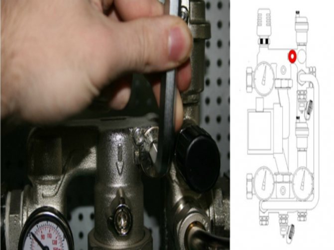
- Remove (unscrew) the protective cap. They are red on Valtec manifolds.
- Loosen the fixing sleeve. If it is not there, we skip this step.
Aligning the Meter with a Retaining Ring - Scroll through the adjusting sleeve until the flow indicator stops at zero.
- We twist in the opposite direction, setting the required value.
Aligning the flow meter without a retainer - If there is a retaining sleeve, screw it in until it stops.
- We put on a protective cover.
So, one by one we expose the flow meters of each floor heating loop. As you understand, there are a little fewer steps without the fixing sleeve.Please note: it is better not to skip the step with setting zero. It doesn't take much time, but it allows you to check the calibration.
Technique for adjusting floor heating flow meters
If everything is done according to the rules, you should have a heat engineering calculation, which indicates the flows in each loop. Do you have a plan? Then, according to the plan, set the values. If not, we will proceed based on the size of the contours. Provided that a pipe of the same cross-section is laid, it will be necessary to change the flow based on the required heat transfer. But in this case, it is necessary to know the length of the pipe in each loop.
Let's look at an example. Let us have four circuits: 90 m, two 75 m and 50 m each. The procedure for adjusting the flow meters of the Valtek collector is as follows:
- On the longest loop, 90 m long, open the flow meter completely (if maximum flow is required) or set the value that is required. Let us assume that for this case the maximum flow rate is needed - 5 m / s. To do this, lower the flow pointer to the very bottom. There is a 5 m / s sign.
For the same length, the streams can be different. Depends on requirements (main heating or additional) or flooring - Let's calculate the required flow rate for 75 meters. Determined by the ratio of lengths: 75/90 = 0.83. The flow rate on the first loop (5 m / s) is multiplied by the resulting figure. It turns out 5 m / s * 0.83 = 4.17 m / s. We set the flow indicator on two loops of 75 m each just below the 4 m / s mark.
- Using the same scheme, we calculate the flow rate for a 50-meter circuit: 50/90 = 0.55. We calculate the required speed of movement of the coolant: 5 m / s * 0.55 = 3.7 m / s. We set the flow indicator a little before reaching mark 4.
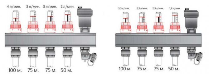
If on the longest loop the flow should be lower than the maximum possible, set the required value on it (at least 3 m / s, at least 2 m / s). The rest are recalculated using this flow rate.
Then we turn on the boiler and check how correctly the collector is configured. With the same length and set the same flow rate, it may turn out that one circuit heats much better. This is due to a different stacking pattern. In a circuit that heats worse, most likely there are more bends or they are steeper. This increases the hydraulic resistance, which reduces the speed of movement of the coolant. This means less heat is transferred. The solution is to slightly increase the consumption and see the result.
How does the water mixing system work?
Mixing system for several rooms
Relatively speaking, the mixing unit for underfloor heating works in this way:
The hot liquid reaches the underfloor heating collector and is stopped by a safety valve if its temperature is too high. From the pressure, a damper is triggered and begins to supply cooled liquid from the return line (which has already passed through the circuit and cooled down). As soon as the temperature becomes optimal, the valve closes back. There are several ways to organize water mixing, which we will discuss below.
Also, often the manifold assembly not only maintains an optimal temperature level, but also increases the pressure in the circuit to improve circulation.
It usually consists of the following elements:
- The safety valve, which we talked about above. It turns on mixing if the temperature gets too hot.
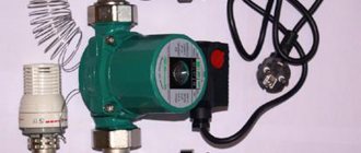
- A circulation pump that increases the water pressure and makes heating evenly.
In addition, the unit may also include a bypass for overload protection, valves for draining water and air vents. Depending on your requirements, it can be assembled in several ways.
The mixing unit is always installed up to the underfloor heating circuit, but the place of its attachment can be different: directly in the room, in the boiler room or in another room in the manifold cabinet.