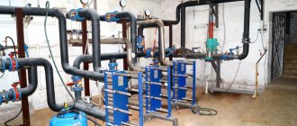
About the installation of additional units
As a rule, in a closed or open radiator heating system, where the heat source is a single boiler, it is enough to install one circulation pump. In more complex schemes, additional units are used for pumping water (there may be 2 or more). They are put in such cases:
- when more than one boiler plant is involved in heating a private house;
- if a buffer tank is involved in the piping scheme;
- the heating system has several branches serving various consumers - batteries, underfloor heating and an indirect heating boiler;
- the same, with the use of a hydraulic separator (hydraulic arrow);
- for the organization of water circulation in the contours of underfloor heating.
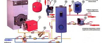
Correct piping of several boilers operating on different types of fuel requires that each of them have its own pumping unit, as shown in the diagram for connecting an electric and a TT boiler. How it functions is described in our other article.
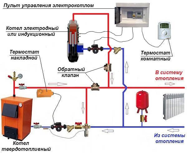
Connection of an electric and TT-boiler with two pumping devices
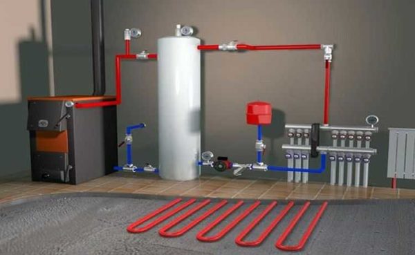
In a circuit with a buffer tank, it is necessary to install an additional pump, because at least 2 circulation circuits are involved in it - a boiler and a heating one.
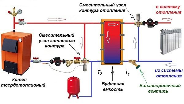
The buffer tank divides the system into 2 circuits, although in practice there are more of them.
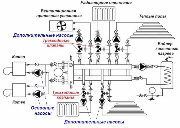
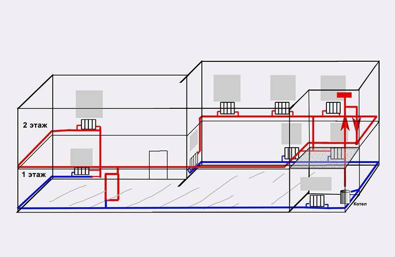
A separate story is a complex heating scheme with several branches, implemented in large cottages on 2-4 floors. Here, from 3 to 8 pumping devices (sometimes more) can be used, supplying the heat carrier floor by floor and to different heating devices. An example of such a scheme is shown below.
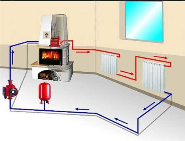
Finally, the second circulation pump is installed when the house is heated with underfloor heating. Together with the mixing unit, it performs the task of preparing a heat carrier with a temperature of 35-45 ° C. The principle of operation of the circuit presented below is described in this material.
This pumping unit makes the heating medium circulate through the heating circuits of the underfloor heating.
Reminder. Sometimes pumping devices do not need to be installed for heating at all. The fact is that most of the wall-mounted electric and gas heat generators are equipped with their own pumping units built into the body.
Features of the image of various types of pipelines
The installation positions of pipelines and elements of sanitary systems in relation to building structures and other pipelines and air ducts, as well as equipment, are determined taking into account building tolerances. When laying in furrows and shafts, pipelines should not be adjacent to the surface of building structures.
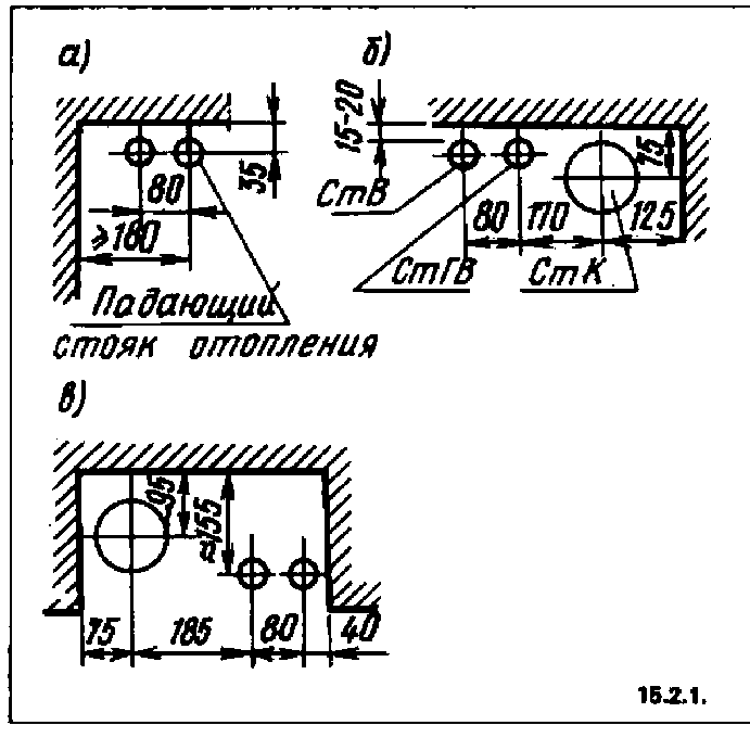
In two-pipe heating and hot water supply systems, the distance between the axes of adjacent non-insulated risers with a diameter of up to 32 mm should be 80 mm, and the supply risers are located on the right (when looking at the wall), as shown in Fig. 15.2.1, a.
At the intersection of risers and connections to devices, the brackets on the risers should bend around the connections from the side of the premises.
The distance from the plaster to the axis of uninsulated risers and horizontal pipelines of heating systems, cold and hot water supply with their open laying, should be with a pipe diameter of up to 32 - 35 mm, with a diameter of 40 - 50 mm. The distance from the floor to the center of the piping to the middle radiators is 640 mm, to the center of the outlet from the radiator to the return riser - 140 mm. Radiator niche depth 30 mm (1/2 brick + 10 mm seam).If the distance from the plastered wall of the niche to the longitudinal axis of the radiator is 160 mm, a “duck” (indent) is not required, at a distance of 130 mm, it is necessary to set the “duck” to 30 mm. The height of the window-sill niche is not less than 750 mm, the width is equal to the battery plus 400 mm (with open piping)
The distance between the vertical hot and cold water connections to the appliances must be 170 mm.
The installation position of the sewer and water pipes with an open laying is shown in Fig. 15.2,1, b, in the niche - in Fig. 15.2.1, c.
The distance from the floor to the center of the revision on the sewer riser is 1000 mm.
Installation height above floor level:
- toilet faucet and water-folding faucet of a cast-iron enameled sink - 1000 mm;
- sink tap - 1100 mm;
- fire hydrant - 1350 mm; to the center of the water supply to the high-located flush cistern - 1975 mm;
- mixing tap in shower rooms - 1000 mm;
- shower net - 2200-2300 mm; the sides of the washbasin, sink and cast-iron enameled sink — 800 mm; the bottom of the flushing cistern - 1800 mm.
Distance from the center of the outlet to the wall from the front side:
- round-side bath - 290 mm;
- straight-sided - 350 mm.
- The smallest pipe laying depth in industrial premises depends on the floor material and the load on it;
- in household premises, laying at a depth of 0.1 m from the floor to the upper generatrix of the pipe is allowed.
When laying gas supply pipelines inside a building, the distance from their outer surface to other communications should be at least:
- from the electric wire - 100 mm;
- from electrical panels, meters, etc. - 300 mm;
- at the intersection with water supply, sewerage, etc. (clearance in the light) —20 mm;
- in the places of passages, the distance from the floor to the pipe is at least 2200 mm;
- from the ceiling of the room to the pipe - not less than 100 mm.
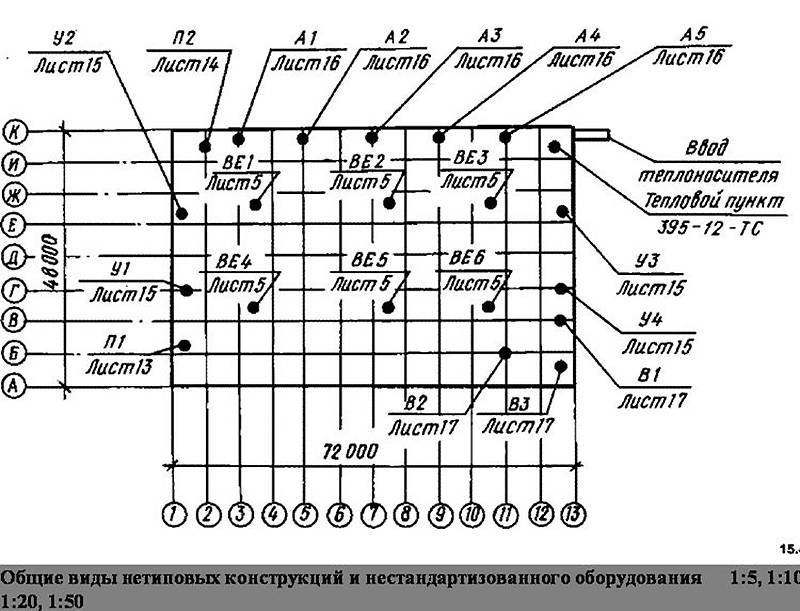
For the correct layout of systems and their sections, it is necessary to take into account the dimensions of fittings, equipment and sanitary fixtures.
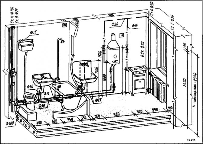
Wiring diagrams are read in conjunction with the floor plans, in which the elements of the systems depicted on them are located. For example, in Fig. 15.2.2 and fig. 15.2.3 shows a general view of the equipment with devices and pipelines of sanitary facilities and kitchens. In both cases, the baths are conventionally removed to show the installation. The premises are full of equipment, branching pipelines, water-folding and shut-off valves. It is easy to imagine the general engineering solution from the visual images, but the design features are not clear.
In the sets of sanitary drawings, several images are developed to show the structures of the systems.
In fig. 15.2.4 shows a fragment of premises with water supply and sewerage pipelines (VK set), shown in Fig. 15.2.3. To link the location of the elements and show the vertical dimensions, the plan is supplemented with axonometric diagrams.
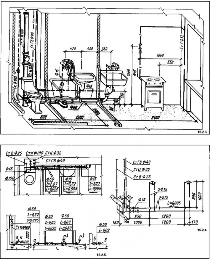
In fig. 15.2.5 shows the sections along the sewer pipelines with the application of fittings. This makes it possible to understand the design of units and division into enlarged elements with a centralized procurement. The combined plans show only the routing of the pipelines. On the sections of the sewer, due to the size of the fittings, the dimensions of which determine the possibility of installation, show all the elements. On each section between the connections, the diameter, length and slope are affixed. The planes of the sections along the sewerage elements are not shown on the plans. The following rule must be observed: the pipeline should be designed on the wall along which it is laid.
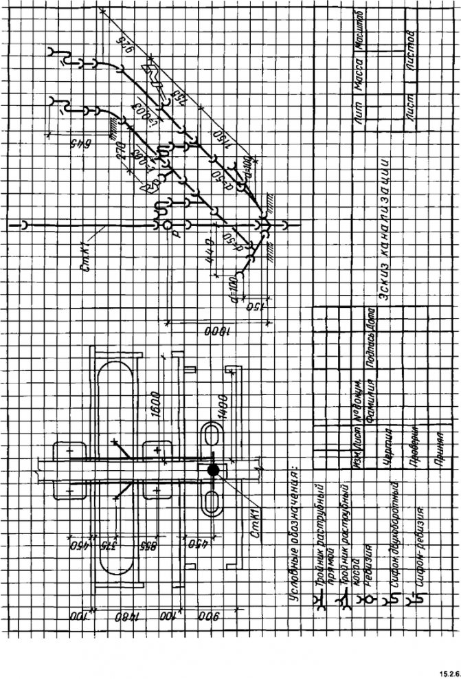
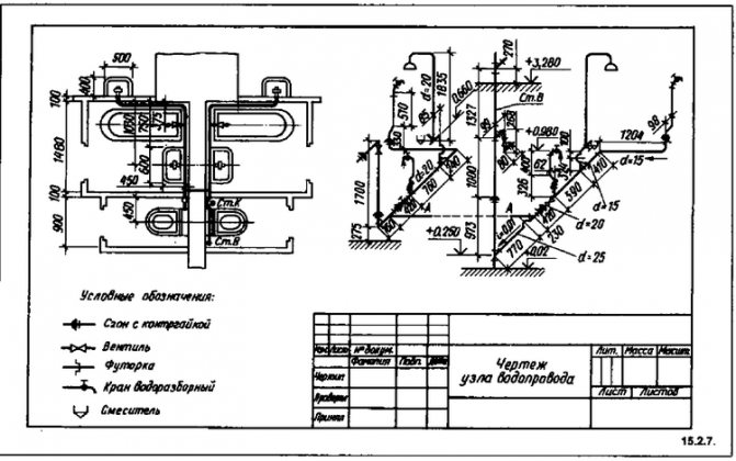
In fig. 15.26 is an example of drawing up an educational sketch of the sewerage system of sanitary facilities and kitchens of adjacent apartments. The educational drawing of the water supply system of such a unit (Fig. 15.2.7) gives an idea of the content of the installation drawing. It depicts another type of "binding" in the vertical direction - the node for connecting the apartment supply to the riser; the positions of the toilet faucet and bath mixer are geodesic marks in relation to the level of the finished floor of the first floor. This designation allows installation up to the installation of a clean floor in the room (in this case, laying ceramic tiles).In industrial construction, vertical reference with marks allows installation before the construction of interiors, mezzanines, etc.
On the plans of buildings or elements of plans, "bindings" of inputs and outputs of pipelines for various purposes are made to the outer dimensions of the structure.
The diameters of the pipelines in the drawing are indicated either by the internal clearance - "conditional passage", denoted by d or dy, or by the external dimension DH. In the latter case, the thickness of the pipe walls is usually also indicated.
When drawing up installation drawings and measurements from nature, the construction lengths of parts are determined with a steel tape.
The construction length L0 is the dimension between the centers of the shaped or connecting parts on the distribution pipeline or riser, as well as between the centers of branches and fittings.
Distances are measured from the centers of fittings and fittings to the points of intersection of the center lines of the bent parts (Figure 15.2.8).
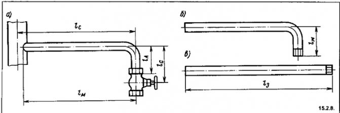
Installation length Lm - the length of the pipeline part without fittings or fittings screwed onto it. It is less than the construction one by an amount equal to the distance from the axis of the fitting to the end of the pipe, i.e. by the amount of the so-called skid.
Blank length L3 - the length of the straight pipe section required for the production of a part by date. The blank length of straight pipe sections without fittings and fittings is equal to the installation length.
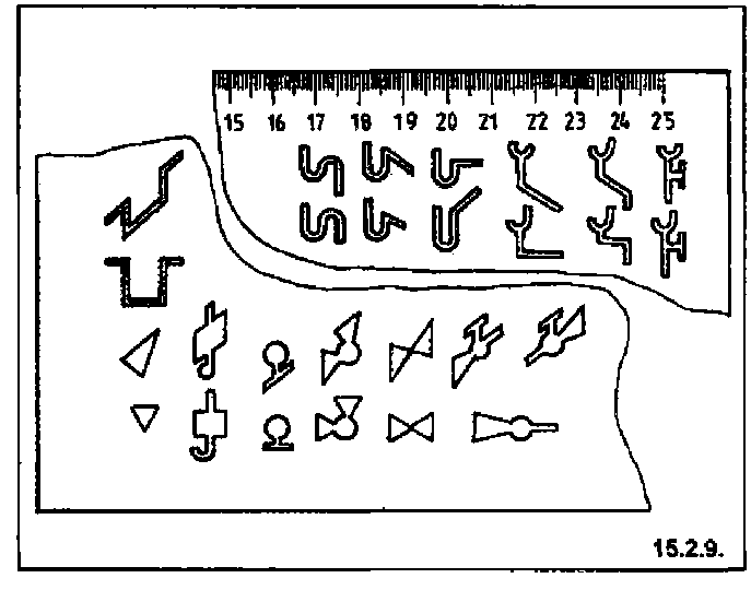
When making drawings of sanitary devices, you have to repeat the image of fittings, heating devices and other designations many times.
Stencils are now being used to ease the work and increase the productivity of designers, which save time when rendering repetitive elements. In fig. 15.2.9 shows a stencil for the image of elements of sanitary systems. The stencil is applied to the bus and, moving along it, the necessary images are applied.
Legends on drawings should be concise and comprehensive.
Material specifications are placed on one sheet with a picture of the system to which they belong, or they are placed on the title sheet.
On the title page, the indexing of elements, sanitary systems and equipment used in the drawings is given.
Conditional indices of devices of the VK system:
- U - washbasin; M - sink;
- R - sink; T - ladder;
- K - toilet bowl (closet bowl);
- F - drinking fountain;
- Urinal;
- B - gutter crown.
On the working drawings of the systems, explications of equipment and material specifications are given.
The working drawings of the supply and exhaust ventilation chambers provide installation specifications for one unit (or product).
The names of parts and assemblies are recorded in the same way as in engineering drawings.
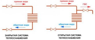
Dependent open heating system
The main feature of the dependent system is that the coolant flowing through the main networks directly enters the house. It is called open because the coolant is taken from the supply pipeline to provide the house with hot water. Most often, such a scheme is used when connecting multi-apartment residential buildings, administrative and other public buildings to heating networks. The operation of the dependent heating system circuit is shown in the figure:
At a temperature of the coolant in the supply pipeline up to 95 ºС, it can be directed directly to the heating devices. If the temperature is higher and reaches 105 ºС, then a mixing elevator unit is installed at the entrance to the house, whose task is to mix the water coming from the radiators into the hot coolant in order to lower its temperature.
The scheme was very popular in the days of the USSR, when few people were concerned about energy consumption.The fact is that the dependent connection with the elevator mixing units works quite reliably and practically does not require supervision, and installation work and material costs are quite cheap. Again, there is no need to lay additional pipes to supply hot water to houses when it can be successfully taken from the heating main.
But this is where the positive aspects of the dependent scheme end. And there are much more negative ones:
- dirt, scale and rust from the main pipelines safely gets into all consumer batteries. Old cast-iron radiators and steel convectors did not care about such trifles, but modern aluminum and other heating devices were definitely not good enough;
- due to a decrease in water intake, repair work and other reasons, there is often a pressure drop in the dependent heating system, and even water hammer. This threatens with consequences for modern batteries and polymer pipelines;
- the quality of the coolant leaves much to be desired, but it goes directly to the water supply. And, although in the boiler house water goes through all stages of purification and desalination, kilometers of old rusty highways make themselves felt;
- regulating indoor temperatures is not easy. Even full bore thermostatic valves quickly fail due to poor quality of the coolant.
Calculation of supply and circulation pipelines
The norms for the consumption of hot water for domestic and industrial needs are established depending on the degree of improvement of buildings and the technological need for heating it from 55 to 65 ° C. However, due to the non-simultaneous consumption of hot water, its flow rate through pipelines differs significantly in value, therefore, the hydraulic calculation of hot water supply pipelines is made according to the actual second flow rates of hot water, which are taken as estimated costs.
The estimated second flow rate, l / s, of hot water during water intake and in pipeline sections is determined by the formula
, (3.6)
Where g
- second hot water consumption by one water-folding device, l / s;
a
- coefficient depending on the total number of water-folding devices in the calculated area and the probability of their operation during the hours of the highest water consumption.
If on the calculated section of the pipeline there are water-folding devices of different performance, then in the formula (3.6) the water consumption for the device with the highest productivity is taken.
Probability of action of water-folding devices R
in a separate building or a group of buildings of the same type and purpose is determined by the dependency
, (3.7)
Where gich
- the rate of consumption of hot water by one consumer per hour of the highest water consumption, l / h;
N
- the total number of taps in a building or group of buildings;
m
- the number of hot water consumers in the building, people.
The purpose of the hydraulic calculation of hot water supply systems is to ensure the required flow rate of hot water with a temperature not lower than: 50 ° C - in closed heat supply systems and 60 ° C - in local systems and in open heat supply systems in all water-folding devices of a building or a group of buildings. In schools, medical and prophylactic institutions and other institutions, the temperature of hot water supplied to washbasin and shower faucets must not be lower than the one set for the project, but not higher than 37 ° C. During the movement of hot water from the heat generator (water heater or mixer) to the water-folding devices, it partially cools down. The permissible cooling of hot water to the farthest draw-off point is taken equal to 5 - 15 ° C, in this regard, the hot water at the outlet of the generator must be superheated by the amount of cooling, but have a temperature of no more than 75 ° C.
The diameters of the supply and distribution pipelines should be taken in such a way that when hot water moves from the inlet to the most remote and high-located point of draw-off, the available pressure in the system is used as much as possible. At the same time, the speed of water movement, taking into account the overgrowing of pipes with deposits of scale and sludge in the supply pipelines and risers, should not exceed 1.5 m / s, and on the branches of the apartment and premises to the water-folding devices - 2.5 m / s.
Before the hydraulic calculation, it is necessary to draw on a scale an axonometric diagram of the hot water supply system (Fig. 3.12). The diagram shows the water supply and coolant inputs oriented according to the building plan, the placement of the water metering unit, accumulator, heater and pumps; the necessary pipeline and water-folding fittings are placed. The diameters of the pipes supplying hot water to the water-folding appliances are taken according to the reference literature.
Fig. 3.12. Design diagram of the hot water supply system: 1, 2,…; 1 ′, 2 ′,… - numbers of nodal points; 1, 2, ... - riser numbers
It is more convenient to start the hydraulic calculation from the most remote and highest point of the draw-off. Therefore, the design diagram of pipelines is divided into sections; sections and risers are numbered in the direction from the most distant point of draw-off to the heat source. The horizontal and vertical dimensions of the calculated areas are determined according to the plans and sections of the building. The calculation of pipelines depends on the presence or absence of circulation in the hot water supply system. Direct-flow hot water supply systems with dead-end wiring are calculated according to the simplest scheme.
In the hydraulic calculation of direct-flow systems, the pressure loss, m, in the calculated sections of the supply pipelines is determined by the formula
, (3.9)
Where i
- specific pressure losses due to friction at the design water flow rate, taking into account the overgrowth of pipes, mm / m;
l
- length of the calculated section of the pipeline, m;
k
- coefficient of local pressure losses. The values of the coefficients of local pressure losses in the formula (3.9) are taken: 0.2 - for supply pipelines; 0.5 - for pipelines within heat points and water-folding risers with heated towel rails; 0.1 - for standpipes without heated towel rails.
The overgrowth of pipes in local and centralized hot water supply systems is taken into account by reducing the inner diameter of the pipes. Therefore, in hydraulic calculations, the specific head loss must be determined by the nearest smaller standard pipe diameters by the amount of overgrowth. In approximate calculations, the overgrowth of pipes is taken into account by an increase in the tabular values of the specific head losses by about 20%. With direct water intake from heating networks, overgrowing of pipes is not taken into account, since the system is filled with network water that has undergone high-quality preparation at the thermal station.
As the number of water-folding devices increases, the diameter of the risers will gradually increase. In order to industrialize installation work in buildings up to 5 floors inclusive, supply risers can be made of pipes of constant diameter along the entire height of the building.
Hydraulic calculation of supply pipelines in circulation systems is carried out according to the same method as in direct-flow systems.
Pros of independent systems
Already on the way to the main consumers of the home water supply network, a whole set of preparatory measures is provided to ensure the distribution, filtration and adjustment of the coolant pressure. All loads fall not on the end equipment, but on a heat exchanger with a hydraulic tank, which directly take resources from the main source. Such resource preparation is practically impossible in private when operating dependent heating systems. The connection of an independent circuit also makes it possible to rationally use water for drinking needs, optimal purification.The streams are divided according to their intended purpose and on each line they can provide for a separate level of preparation corresponding to the technological requirements.
Cons of dependent heating systems
Of the negative aspects of the operation of such systems, the following are noted:
- Intensive contamination of working circuits with scale, dirt, rust and all kinds of impurities that may well get into consumer equipment.
- Higher requirements for carrying out repairs. The fact is that dependent and independent heating systems in such cases require the connection of specialists of different levels. It is one thing to make repairs on the main line once a year, and it is another thing to carry out a comprehensive inspection of the elevator unit piping at home on a monthly basis.
- Water hammer is possible. Improper connection of communications or excessively high pressure in the circuit can lead to rupture of pipes.
- Low base quality of the coolant in terms of composition.
- Complexity of control and management. At technological stations of communal water heating, the process of updating the same shut-off valves is rather slow, hence violations in pressure balances may occur.
Useful Tips
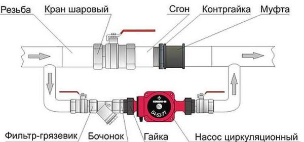
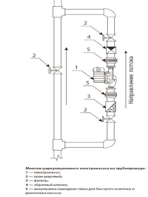
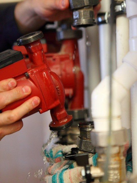
To exclude an arbitrary change in the water flow, shut-off valves are attached in the area of the inlet-outlet of the circulation pump. The connecting nodes must be treated with a "sealant", which will increase the performance of the entire heating system.
To quickly and correctly install the pump pump, you need selected connections and threads. To reduce the search time for all the necessary parts, look in the plumbing stores for a special device with already selected fasteners. After completing the installation of the pumping unit, the system is filled with water or other coolant.
Before starting the system, open the central valve to remove air locks - water will notify about complete removal of air from the system.
About quantity and breakdowns
The number of circulation pumps required to heat a private house can be determined based on the entire length of the pipeline. If its length is about 80 m, then one is enough. If this length is exceeded, you need to think about increasing the number of pumps in the system.
The reasons for the failure of circulation pumps can be incorrect installation, arbitrary location of the cable and terminal module, as well as non-observance of the rules for operating the heating boiler
To avoid malfunctions, it is important not to ignore the regular air release procedures and take care of good cleaning of the system from mechanical particles.
But it should be remembered that all breakdowns of the circulation pump must be corrected by specialists. Therefore, if faults have already appeared and found, then it is best to contact the repair service.
Pipeline
In modern technology, pipelines refer to such devices that are designed to transport a variety of liquid, gaseous and bulk media. The main components of piping systems are: straight pipes that are tightly connected to each other; suspensions and supports; control and measuring equipment; locking and regulating devices; fasteners; seals and gaskets; automation equipment.
In addition, the elements of pipeline systems include the materials necessary to ensure effective protection of all of the above components from the harmful effects of low and high temperatures, as well as from electrochemical corrosion.
The locations of the elements of pipeline systems are their branches, turns, as well as transitions to a different diameter. They serve to ensure a long service life of the system as a whole, as well as the tightness of the entire structure.Practice shows that without such elements as bends, tees and transitions, almost no pipeline system is now implemented.
Where to put
It is recommended to install a circulation pump after the boiler, before the first branch, but on the supply or return pipeline - it doesn't matter. Modern units are made of materials that can tolerate temperatures up to 100-115 ° C. There are few heating systems that work with a hotter coolant, therefore considerations of a more "comfortable" temperature are untenable, but if you feel calmer, put it in the return line.
Can be installed in the return or direct pipe after / before the boiler before the first branch
There is no difference in hydraulics - the boiler, and the rest of the system, it does not matter at all whether there is a pump in the supply or return line. What matters is the correct installation, in terms of strapping, and the correct orientation of the rotor in space
Nothing else matters
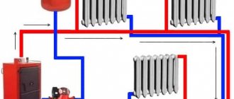
There is one important point at the installation site. If the heating system has two separate branches - on the right and left wings of the house or on the first and second floors - it makes sense to put a separate unit on each, and not one common one - directly after the boiler. Moreover, the same rule remains on these branches: immediately after the boiler, before the first branch in this heating circuit. This will make it possible to set the required thermal regime in each part of the house independently of the other, as well as save on heating in two-story houses. How? Due to the fact that the second floor is usually much warmer than the first, and much less heat is required there. In the presence of two pumps in the branch that goes up, the speed of movement of the coolant is set much less, and this allows you to burn less fuel, and without compromising the comfort of living.
There are two types of heating systems - forced and natural circulation. Systems with forced circulation cannot work without a pump, with natural circulation they work, but in this mode they have a lower heat transfer. Nevertheless, less heat is still much better than its complete absence, because in areas where electricity is often cut off, the system is designed as a hydraulic system (with natural circulation), and then a pump is cut into it. This gives high efficiency and reliability of heating. It is clear that the installation of a circulation pump in these systems is different.
All heating systems with underfloor heating are compulsory - without a pump, the coolant will not pass through such large circuits
Forced circulation
Since the forced circulation heating system is inoperative without a pump, it is installed directly in the break in the supply or return pipe (of your choice).
Most problems with the circulation pump arise due to the presence of mechanical impurities (sand, other abrasive particles) in the coolant. They are able to jam the impeller and stop the motor. Therefore, a strainer-sump must be installed in front of the unit.
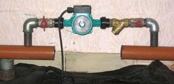
Installation of a circulation pump in a forced circulation system
It is also desirable to install ball valves on both sides. They will make it possible to replace or repair the device without draining the coolant from the system. Turn off the taps, remove the unit. Only that part of the water that was directly in this piece of the system is drained.
Natural circulation
The piping of the circulation pump in gravity systems has one significant difference - a bypass is required. This is a jumper that makes the system operational when the pump is not running. One ball shut-off valve is placed on the bypass, which is closed, all the time while the pumping is running. In this mode, the system works as a forced one.
Installation diagram of a circulation pump in a system with natural circulation
When electricity fails or the unit fails, the crane on the lintel is opened, the crane leading to the pump is closed, the system works like a gravity system.
Installation features
There is one important point without which the installation of a circulation pump will require alteration: it is required to turn the rotor so that it is directed horizontally. The second point is the direction of the flow. There is an arrow on the body indicating which direction the coolant should flow. This is how you turn the unit so that the direction of movement of the coolant is “in the direction of the arrow”.
The pump itself can be installed both horizontally and vertically, only when choosing a model, see that it can work in both positions. And one more thing: with a vertical arrangement, the power (created pressure) drops by about 30%. This must be taken into account when choosing a model.
List of equipment and parameters on the diagram
On the heating diagram of any floor, the following should be indicated:
- Piping with indication of all pipe diameters;
- Pipe insulation sections - length and thickness. Such insulation is indicated graphically;
- Piping axis relative to zero level;
- Pouring slope angles;
- If there are gaps in the horizontal sections of the filling, then the sizes of these sections are indicated;
- Supporting and suspension elements, expansion joints.
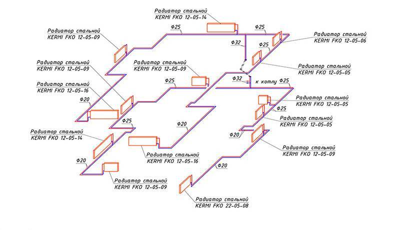
An example of the removal of symbols on a heating scheme
- The outrigger shelf is used to designate shut-off valves with an indication of their marking and type. Under the offset, the designation of the part is indicated according to the documentation (see the figure above);
- Vertical horizontal piping with appropriate designations;
- All heating devices present in the diagram.
Mandatory requirement: you must specify the type and main characteristics of these elements:
- How many sections does the heating radiator contain;
- How many sections or pipes are in the heating register, its diameter and total length;
- For other heating devices (convectors, radiators) - the type of device;
- Designations of heating installations (boilers, heating furnaces and heat exchangers, circulation and heat pumps, elevators, etc.);
- Mortgage equipment;
- Measuring instruments.
Heating diagram to scale
Heating equipment and calculations
All equipment used in the heating system is divided into auxiliary and main. The main one is a boiler or other heating device, the auxiliary one is radiators and distribution pipes with the attached fittings. To calculate the parameters of the necessary heating equipment, the specific power of the boiler is required, which varies depending on the climatic zones:
- For the regions of the Far North - 1.5-2.0 kW;
- For a temperate climatic zone and central regions - 1.2-1.5 kW;
- For the southern zones - 0.7-0.9 kW.
Based on these amendments, the power of the heating device is calculated using the formula:
Wboiler = S x W / 10;
Where W is the estimated power of the heating device (boiler, convector, etc.);
S is the total area of the heated object.
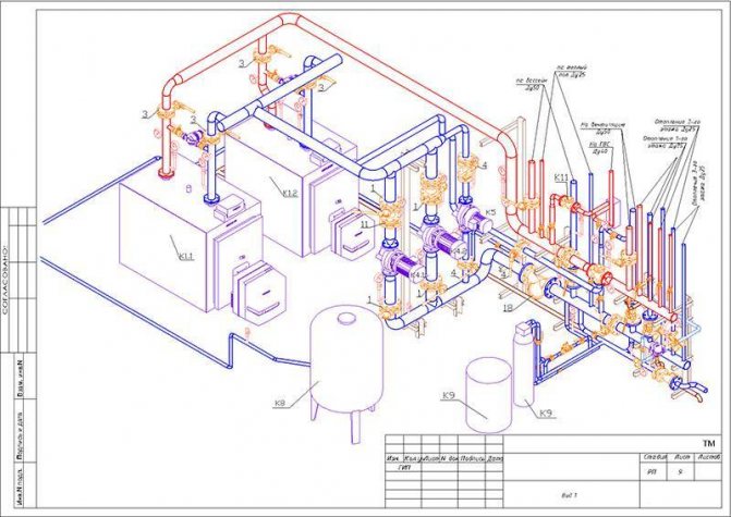
Axonometric diagram of boiler equipment with two burners
Pumps are heat and circulating. In most cases, except for low-rise buildings with natural circulation of the coolant, it is impossible to do without pumping equipment, therefore, in almost all schemes, these devices are present. Pumps must meet certain technical requirements, including the following:
- Ease of installation, dismantling, ease of operation and maintenance;
- Low noise and efficiency of the device;
- Reliability and durability of operation.
Three types of heating systems are used in low-rise residential buildings:
- The classic two-pipe scheme, according to which hot water is supplied through one pipe and returned through the second. In this scheme, the pump is mounted on the return line;
- Diagram with a vertical riser. In this scheme, hot water is also supplied to the radiators through one pipe, and returned through the second, but the circulation pump is installed on the outlet pipe to supply the hot coolant. Thus, hot water first passes through the upper radiators, and then moves to the lower batteries of the system;
- The one-pipe scheme assumes the movement of the coolant sequentially from the radiator to the radiator with a return to the boiler. This is the simplest scheme, but due to its low efficiency, it is used in small one-story buildings.
Simplified axonometric two-pipe diagram
Calculations when drawing up a heating scheme should take into account:
- Heat consumption in each room;
- Type and number of radiators;
- The number of risers, if any, as well as the total number of branches and circuits;
- Heating device connection diagram;
- Parameters of pipes and valves.
After finishing the calculations of the heating system, they must be indicated on the diagram. The main purpose of the axonometric heating scheme is a graphical display of all parts and elements, but, in addition, the diagram should also display the technical characteristics of the heating equipment. Also, the scheme should contain calculations for the supply of heat to each room of the house, including utility rooms.
Circulation pump insert
If the pump was not previously included in the heating system. its "tie-in" into the pipeline is required. Since this operation requires some skills and special equipment from the contractor, it can be entrusted to professionals, or you can do the work yourself, having previously familiarized yourself with the technology of installing pipelines. The order of work and the list of equipment used will depend on the chosen tie-in method and pipeline material.
There are 2 ways to insert a circulation pump:
- on the main section of the pipeline;
- on the bypass section (bypass).
Installation of the unit on the main site requires less time and money, but has one significant drawback. The pump operates from the power supply, therefore, with this method of installation, when the light is turned off in an apartment or house, the heating will not be able to function.
The second method is more complicated, but provides the heating system with an increased level of autonomy. In this case, when the system is operating in normal mode, the coolant moves along the bypass channel, and the corresponding section of the main line is blocked using a specially installed ball valve. During a power outage, the valve opens and fluid flows naturally through the pipeline.
Installation diagram of the pump on the bypass channel (bypass).
This option, although common, has one big drawback - a crane on the main highway. It is better if a ball valve is installed instead of a tap.
Installation of a pump on the delivery of a gas floor boiler in a natural circulation heating system. An article on the topic "How to choose a gas boiler" may be useful to you.
In normal operation, the valve is closed by the overpressure created by the pump above the ball. If the pump is de-energized, the ball rises under the pressure of water moving naturally along the line. This option is relevant if the installation of the pump, for one reason or another, is carried out at "supply".
The pump tapping mounting kit includes:
- pipes of the required diameter;
- elements of pipeline fittings;
- union nuts (for polypropylene pipelines) or squeegees (for steel pipes);
- mud filter;
- shut-off valves;
- check valve.
The diameter of the pipes for tapping must correspond to the diameter of the already installed pipeline, and their total length is determined based on the results of measurements at the site of the proposed installation of the pump. The set of pipeline fittings is selected in the same way.Union nuts (or sleeves) are used for quick installation and removal of the pump.
A dirt filter is installed directly in front of the unit inlet. It is necessary to protect the pump from the ingress of contaminants, the source of which can be deposits on the inner surface of the pipelines. The drain hole of the filter must point downwards to allow periodic cleaning.
Stop valves are installed at the pump inlet in front of the filter and at the outlet of it, so that, if necessary, the unit can be dismantled without stopping the entire system. When installing the blower on the bypass section, an additional valve is installed on the main line parallel to the pump. The check valve is designed to protect the system from water hammer. It is mounted at the pump outlet in front of the shut-off valve.
Engineering systems
Table 2.1 - General designations.
| Designation | Name | The code |
| Water pipes | 2.1.01 | |
| Heat pipe | 2.1.02 | |
| Refrigeration pipe | 2.1.03 | |
| Freon | 2.1.04 | |
| Draining | 2.1.05 | |
| Gravity drainage | 2.1.06 | |
| Pressure drainage | 2.1.07 | |
| Exhaust air | 2.1.08 | |
| Pipe brand, with a detailed description | 2.1.09 | |
| Pipe mark (for hidden or underground laying), with a detailed description | 2.1.10 | |
| Pipe mark existing | 2.1.11 | |
| Thermally insulated pipeline | 2.1.12 | |
| Pipeline slope, mm / m or% | 2.1.13 | |
| Direction of flow (liquid) in the pipeline | 2.1.14 |
Table 2.2 - Water pipelines.
| Designation | Name | The code |
| Drinking | 2.2.01 | |
| Fireproof | 2.2.02 | |
| Industrial | 2.2.03 | |
| Recirculated water supply | 2.2.04 | |
| Reverse water, reverse | 2.2.05 | |
| Softened water | 2.2.06 | |
| River water | 2.2.07 | |
| River clarified water | 2.2.08 | |
| Underground water | 2.2.09 |
Table 2.3 - Heat pipelines.
| Designation | Name | The code |
| Hot water supply (heat supply, heating) | 2.3.01 | |
| Hot water, return (heat supply, heating) | 2.3.02 | |
| Hot water supply at different parameters | 2.3.03 | |
| Hot water reverse at different parameters | 2.3.04 | |
| Hot water supplying hot water supply | 2.3.05 | |
| Hot water circulating hot water | 2.3.06 | |
| Hot water supplying hot water supply with different parameters of the heat carrier | 2.3.07 | |
| Hot water, circulating hot water supply with different parameters of the heat carrier | 2.3.08 | |
| Hot water feeding technological processes | 2.3.09 | |
| Hot water, reverse technological processes | 2.3.10 | |
| Hot water supplying technological processes with different parameters of the heat carrier | 2.3.11 | |
| Hot water, reverse technological processes with different parameters of the heat carrier | 2.3.12 | |
| Steam line | 2.3.13 | |
| Condensate line | 2.3.14 | |
| Steam pipelines of different parameters of steam pressure | 2.3.15 | |
| Condensate lines with different steam pressure parameters | 2.3.16 | |
| Pressure condensate line | 2.3.17 | |
| Antifreeze (ethylene glycol, propylene glycol, etc.) | 2.3.18 | |
| Antifreeze (ethylene glycol, propylene glycol, etc.), reverse | 2.3.19 | |
| Heat pump supply | 2.3.20 | |
| Heat pump, reverse | 2.3.21 |
Table 2.4 - Cooling lines.
| Designation | Name | The code |
| Chilled water supply | 2.4.01 | |
| Chilled water, reverse | 2.4.02 | |
| Antifreeze feeding | 2.4.03 | |
| Antifreeze, reverse | 2.4.04 | |
| Freon, hot gas | 2.4.05 | |
| Freon, cold gas | 2.4.06 | |
| Freon liquid | 2.4.07 |
Table 2.5 - Pipe assemblies.
| Designation | Name | The code | |
| On plans and sections | On the diagrams | ||
| Pipeline | 2.5.01 | ||
| Flexible pipeline | 2.5.02 | ||
| Crossing pipelines without connections | 2.5.03 | ||
| Elbow, bend | 2.5.04 | ||
| Elbow (rectangular) | 2.5.05 | ||
| Elbow 135 ° | 2.5.06 | ||
| Knee going to the visible side or up, image in two lines | 2.5.07 | ||
| The knee going to the invisible side or down, the image in two lines | 2.5.08 | ||
| Knee going to the visible side or up, image in one line | 2.5.09 | ||
| Knee going to the invisible side or down, image in one line | 2.5.10 | ||
| Plug (plug) | 2.5.11 | ||
| Concentric reducer | 2.5.12 | ||
| Tee | 2.5.13 | ||
| Crosspiece | 2.5.14 | ||
| Branch | 2.5.15 | ||
Table 2.6 - Pipe connections.
| Designation | Name | The code | |
| On plans and sections | On the diagrams | ||
| General | 2.6.01 | ||
| Flanged | 2.6.02 | ||
| Socket threaded | 2.6.03 | ||
| Coupling quick-release | 2.6.04 | ||
| Spherical hinge | 2.6.05 | ||
Table 2.7 - Elements of pipelines.
| Designation | Name | The code |
| Pipeline in a pipe (case) | 2.7.01 | |
| Pipe in the gland | 2.7.02 | |
| Siphon (odor trap) | 2.7.03 | |
| Compensator, general designation | 2.7.04 | |
| U-shaped compensator | 2.7.05 | |
| Compensator stuffing box double-sided and one-sided | 2.7.06 | |
| Bellows compensator | 2.7.07 | |
| Flexible insert | 2.7.08 | |
| Place of resistance in the pipeline (throttle washer, diaphragm) | 2.7.09 | |
| Fixed support | 2.7.10 | |
| The support is movable | 2.7.11 | |
| Movable support, suspension | 2.7.12 | |
| Thermometer well | 2.7.13 | |
| Air outlet, general designation | 2.7.14 | |
| Manual air release | 2.7.15 | |
| Air collector with manual air release | 2.7.16 | |
| Automatic air vent | 2.7.17 | |
| Water drain, general designation | 2.7.18 | |
| Manual drainage | 2.7.19 | |
| Drainage, drain funnel | 2.7.20 | |
| Drainage, floor drain | 2.7.21 |
Table 2.8 - Fittings.
| Designation | Name | The code |
| Shut-off valve straight through | 2.8.01 | |
| Angle valve | 2.8.02 | |
| Gate valve | 2.8.03 | |
| Disk shutter | 2.8.04 | |
| Ball valve | 2.8.05 | |
| Straight through valve, cork | 2.8.06 | |
| Corner valve, cork | 2.8.07 | |
| Three-way valve, cork | 2.8.08 | |
| Control valve straight through | 2.8.09 | |
| Angle control valve | 2.8.10 | |
| Three-way control valve | 2.8.11 | |
| Four-way control valve | 2.8.12 | |
| Shut-off and balancing valve, manual | 2.8.13 | |
| Automatic balancing valve | 2.8.14 | |
| Check Valve | 2.8.15 | |
| Check valve, angular | 2.8.16 | |
| Radiator shut-off valve | 2.8.17 | |
| Radiator shut-off valve with bypass | 2.8.18 | |
| Automatic radiator thermostat | 2.8.19 | |
| Differential pressure regulator | 2.8.20 | |
| Pressure regulator behind | 2.8.21 | |
| Upstream pressure regulator | 2.8.22 | |
| Safety valve, angle | 2.8.23 | |
| Safety valve, straight through | 2.8.24 | |
| Float valve | 2.8.25 |
Table 2.9 - Fittings.
| Designation | Name | The code |
| Sump | 2.9.01 | |
| Mesh filter | 2.9.02 | |
| Condensate drain (steam trap) | 2.9.03 | |
| Flowmeter, general designation | 2.9.04 | |
| Ultrasonic flow meter | 2.9.05 | |
| Electromagnetic flowmeter | 2.9.06 | |
| Flowmeter, orifice plate with flanges | 2.9.07 | |
| Turbine flow meter | 2.9.08 | |
| Vortex flow meter | 2.9.09 |
The material used images of symbols from the Visio Library Engineering Systems, designed to create drawings and diagrams of heating, ventilation, gas supply, sanitary systems, power equipment, etc.
All ABOK materials 1.05-2006
- ABOK 1.05-2006 Symbols in heating, ventilation, air conditioning and heat and cold supply projects.
- ABOK 1.05. Appendix 1. Symbols of ventilation systems.
- ABOK 1.05. Appendix 2. Symbols of pipelines.
- ABOK 1.05. Appendix 3. Symbols of equipment.
- ABOK 1.05. Appendix 4. Symbols of equipment for cleaning ventilation emissions.
- ABOK 1.05. Appendix 5. Symbols of automation elements and drives.
Installing the pump
After the pipeline section is fully prepared, you can proceed directly to the installation of the unit itself. The rotor supports of the pumps used in heating systems are not designed for operation in the vertical position of the unit, therefore only its horizontal arrangement is allowed.
Installing the pump with an incorrect rotor axis.
The scope of delivery of the circulation pump includes the unit itself with a built-in or external power supply, gaskets, a passport for the product and instructions for installation and operation. Before starting the installation, you must read the contents of the instructions in order to take into account all the features of the installation process and connection of a specific model. Some pumps are shipped without seals and must be purchased separately.
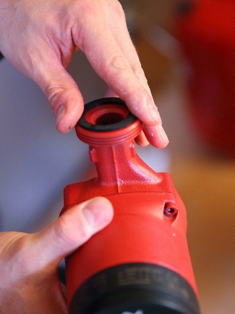
Installation of a sealing gasket.
If the pump is mounted on a vertical section of the pipeline, then its lower flange is placed on the counter flange of the pipeline, on which the sealing gasket is placed, after which the connection is screwed using the union nut. Then the seal is placed on the top flange of the pump and the connection is screwed on with a second nut. Then the nuts are tightened with a wrench. In some cases, the threaded connections of the pump with the pipeline are additionally sealed with a sealing tape. When installing on a horizontal section, any sequence of flange connections is allowed.
Installation of a circulation pump.
Then it is necessary to open the taps on both sides of the unit so that the internal cavities of the pump are filled with liquid. If the design of the blower does not include an automatic air release valve, it is vented using a special screw that opens the bypass hole.
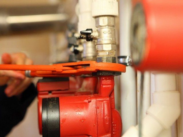
Tightening the union nut.
After installing the pump in the pipeline, it must be connected to the power supply. The power socket for the unit must be grounded. If the pump provides for the possibility of multi-mode operation, you should switch the lever to the desired mode. The heating circulation pump connected to the power supply begins to perform forced circulation of the heating medium, providing more intensive heat exchange and saving the boiler fuel by reducing the temperature difference of the heating medium in the supply and return lines.
Interior solution: decorative grilles for heating radiators
Optimum thermal insulation for heating pipes
Self-insulation of heating pipes on the street
Pipelines: Main types and categories
- TPA directory
- Basics and concepts of pipeline valves
- Pipelines: Main types and categories Pipelines: Main types and categories
Pipelines: Main types and categories Pipelines - types and categories Pipeline is called a device designed to transport liquid, gaseous or bulk substances. The main types of pipelines are shown in the figure below. Depending on the transported medium, the following terms are used: water pipeline, gas pipeline, steam pipeline, oil pipeline, air pipeline, oil pipeline, acid pipeline, oxygen pipeline, gas pipeline, milk pipeline, etc. The main general parameters of the pipeline and fittings are: - Nominal diameter of the passage DN (Dy), mm, - Nominal pressure РN (py), MPa - Working temperature tp, ° С of the medium. Distinguish between working pressure pp, MPa and test pressure pp, MPa.
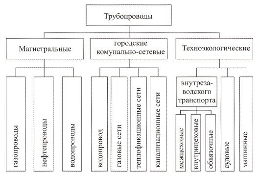
Main pipelines are intended for transportation of medium over long distances. The main pipeline includes facilities for the preparation of the transported medium, the linear part, pumping or compressor and gas distribution stations. According to the operating pressure, main gas pipelines are subdivided into low pressure pipelines - pp <1.2 MPa, medium pressure - pp = 1.2 ... 2.5 MPa and high pressure - pp> 2.5 MPa. Urban (settlement) utility-network pipelines are used to meet the needs of the urban population and small industrial enterprises. Gas pipelines of the city gas economy, depending on the purpose, are subdivided into transit, distribution and branches. Gas transportation through the city gas pipeline is allowed at pp <1.2 MPa by the current regulations. City gas pipelines are considered low pressure at pp <0.005 MPa, medium pressure at pp = 0.005 ... 0.3 MPa and high pressure at pp> 0.3 MPa. Pipelines are called technological industrial enterprises through which raw materials, semi-finished products and finished products are transported, steam, water, fuel, reagents and other materials that ensure the implementation of the technological process and the operation of equipment, waste reagents and gases, various intermediate products obtained or used in the technological process, production waste ... Depending on the location at an industrial facility, process pipelines are subdivided into intrashop, connecting the units and machines of the process units of the workshop, and inter-workshop, connecting the process units of different workshops. Intrashop pipelines are called piping if they are installed directly within individual devices, pumps, compressors, etc. and connect them. Process pipelines are divided into five categories depending on the nature of the transported medium, operating pressure and operating temperature. The category of the pipeline is established by the project. Process pipelines are considered cold if they operate in an environment with an operating temperature tp <50 ° C, and hot if the temperature of the working environment is tp> 50 ° C. Depending on the nominal pressure of the medium, pipelines are subdivided into vacuumoperating at an absolute pressure of the medium below 0.1 MPa (abs), low pressureoperating at medium pressure from 0.1 to 1.6 MPa or from 0 to 1.5 MPa (g), medium pressureoperating at medium pressure from 1.5 to 10 MPa (g). Non-pressure pipelines are calledoperating without overpressure ("gravity"). Depending on the degree of aggressiveness of the transported medium, pipelines are divided into three groups: with a non-aggressive and low-aggressive medium (corrosion rate less than 0.1 mm / year), with a medium-aggressive medium (corrosion rate 0.1-0.5 mm / year) and with a highly aggressive one. medium (corrosion rate more than 0.5 mm / year). Depending on the maximum working gas pressure, gas pipelines and gas installations are: low pressure (at pp <0.015 MPa and at 0.015 MPa
Portal of pipe fittings Armtorg.ru
Barnaul, Factory 9th passage, 5g / 8.
+7 (3852) 567-734; +7 (3852) 226-927
Share this
Previous article Next article
← Back to section Fundamentals and concepts of pipeline fittings ← Back to the table of contents of the directory
Latest registered companies (Register a company)
Trading House "NHI-Group"
Russia, Krasnodar Territory
NefteKhimEngineering
Russia, Moscow region
Boiler plant
Russia commodity cloud
In other ... .2038 units klapanov127 safety valves bronzovye123 stalnye932 Gates Gates Gates chugunnye571 energeticheskie145 nerzhaveyuschie368 Latches Latches Catches, steel stalnye2161 - HL369 chugunnye1101 Latches Latches Paddles energeticheskie89 stalnye292 gates chugunnye334 Test equipment for TPA119 obratnye954 Valve Valve Valve otsechnye60 predohranitelnye1108 Valve Valve reguliruyuschie557 energeticheskie128 Compensators Condensate silfonnye204 stalnye55 Condensate boiler chugunnye67 oborudovanie220 bronzovye149 Cranes Cranes Cranes nerzhaveyuschie170 stalnye620 steel cranes - cranes HL87 chugunnye149 Manometry88 Metizy433 Nasosy247 Otvody1079 Heating oborudovanie96 Switching ustroystva46 Perehody461 Fire armatura48 Radiatory33 Regulatory armatura313 repairing equipment TPA53 Counters vody146 Termometry38 Troyniki488 Truby702 Pointers urovnya71 Sealing materialy67 Filters gryazeviki380 Fitingi205 Fl antsy2399 Ball valves1197 Electric actuators249
Is it possible to convert one system to another
Theoretically, this is quite possible - both in one direction and in the other. Basically, they are just upgrading dependent systems, but there may well be a need to reconstruct an independent infrastructure. At the same time, the most rational option, when it will be possible to preserve the advantages of both systems with varying degrees, will be the implementation of an independent heating system with closed input circuits. This means that the functions that were performed by a separate manifold block with a complete set of control units in the standard independent scheme, in this case, will be taken over by point-installed devices. At different levels of the already home network, before approaching consumers, it is possible to insert filters, compressor units, distributors, circulation pumps and a hydraulic tank.
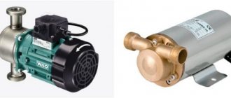
Classification
Aggregates are of two types. The first type is dry pumps. In this type of equipment, the coolant and the rotor do not interact with each other. The working part of the rotor is isolated and separated from the motor by stainless steel O-rings. When the rings are started up, a thin water film seals the joints due to the different pressures in the system and in the environment.
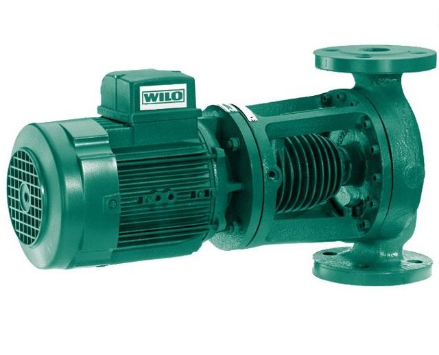
The efficiency of a "dry" unit is about 80%. This equipment is very sensitive to water contamination in the system, and if small particles enter, it quickly breaks down. The dry type pump works quite noisy, therefore, when installing it, you should take care of the soundproofing of the room.
"Wet" pumps differ in their design from "dry" ones. Its impeller is located directly in the coolant. The stator and the moving part of the mechanism are separated by a special glass that provides waterproofing of the engine. "Wet" units are cheaper both in operation and in repair, they work quieter than "dry" ones.
The disadvantages of "wet" type equipment include their low efficiency ⎯ only about 50%. This is due to the low sealing of the sleeve separating the stator and the coolant. Although even this performance is quite enough for heating any private house.