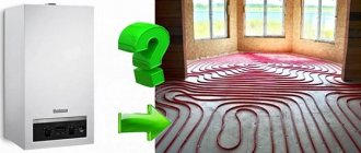
The purposefulness of the installation of the collector system
But it is impossible to install a collector heating system in an apartment of old multi-storey buildings, because a tee heating system already works there. For the collector system to work, it is necessary to close the hydraulic circuit, which is necessary to create circulation of the coolant in the system. If a closed hydraulic circuit is created in one apartment, the other apartments will be cut off from the heating system.
The collector heating system also cannot be used in areas with an unstable power supply, since when the circulation pump stops, the water will freeze and the pipes will fail. But the situation can be somewhat improved by using
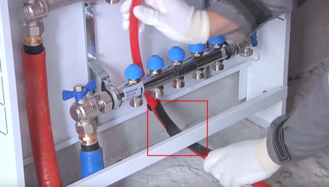
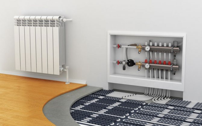
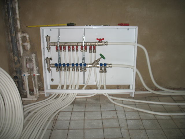
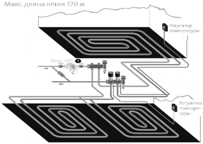
Underfloor heating and the place occupied by the collector with flow meters
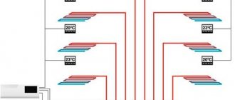
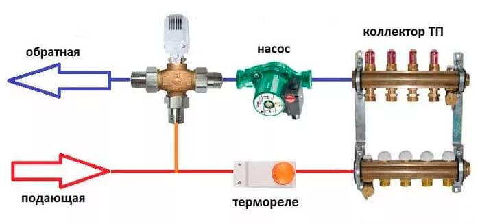
The peculiarity of a warm floor as a heating system is that the heated coolant, moving along the heating circuit, transfers part of the thermal energy to the floor surface. Thus, due to the heating of the floor, heat is transferred to the air mass circulating inside the room in the direction from bottom to top. A number of devices are involved in the supply of warm water to heating circuits, the intensity and flow rate, including:
- three-way valve;
- circulation pump;
- collector.
The control over the distribution of the coolant is carried out by the flow meter for the warm floor. This device plays one of the key roles in the operation of the entire pumping and mixing group. Collectors for underfloor heating are designed to supply hot water and collect waste heat carrier for its further use in the pipeline of the heating system. In the pumping and mixing unit, hot water coming from a heating source is mixed with a coolant returned to the circuit - a return flow. The functionality and efficiency of underfloor heating are based on this operating principle.
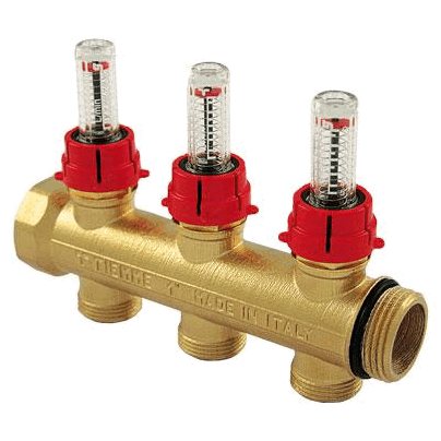
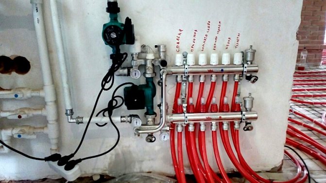
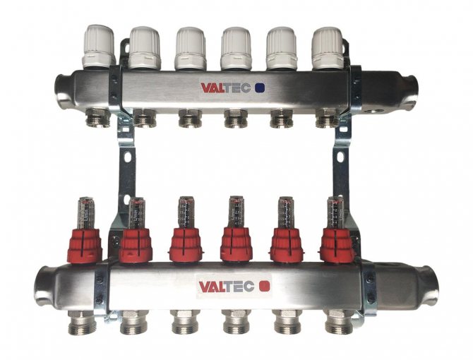
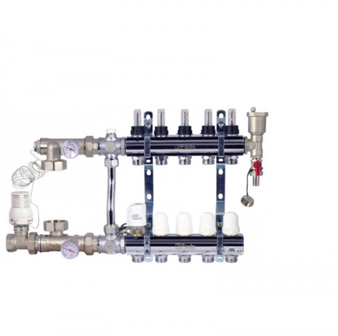
Mixing unit with rotameters for underfloor heating systems
Together with the operation of safety valves, rotameters are designed to regulate the temperature of the coolant in individual water floor circuits. Thanks to these devices, the required volume of treated water is supplied to the underfloor heating system. In other words, this equipment monitors the amount of coolant in the water heat pipe, and therefore, the functionality of the entire heating system.

Collector heating system. The principles of its work.
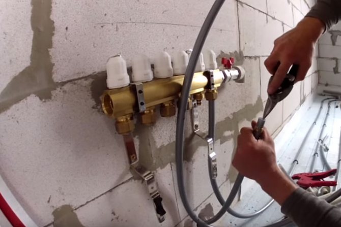
How to install a mixing unit for a warm floor with your own hands
As I said earlier, this type of heating system is most often used in two or more storey buildings. But no one will forbid you to use it in a one-story house. It all depends on expediency. In addition to heating devices, an indirect heating boiler or a pool or greenhouse heating system can be connected to the manifold. So this kind of trick can be used in a one-story house. The main thing is not to forget that only forced circulation of the coolant can be in the collector heating system. This means that it must have at least one, and most often several circulation pumps. We look at the picture below:
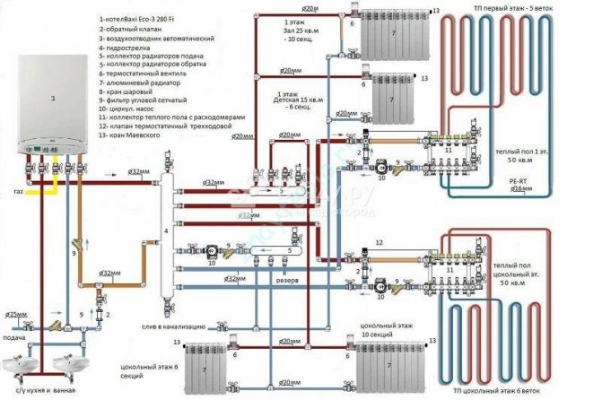
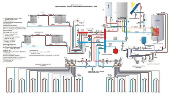
The figure shows a diagram without an indirect heating boiler. This is done here because a double-circuit gas boiler is used. Well, if the boiler is single-circuit, then everything will look a little different:
It has everything modern homeowners love:
- Radiators.
- Water heated floors.
- Reserve electric boiler.
- Indirect heating boiler.
If you do not count together with the boiler pump, then there will be 5 of them. In order for the circulation pumps not to create a pressure difference between the “supply” and “return” collectors, a hydraulic arrow is used here. Thanks to it, the boiler circulation pump can always provide the required flow rate of the heat carrier through the boiler heat exchanger, which has a positive effect on its service life. The underfloor heating circuits are connected through their collectors with autonomous circulation groups. Here you need to take into account the possibility of an emergency power outage. To ensure the operation of the "brain" of the boiler and circulation pumps during shutdown, you will need. Without it, the circulation of the coolant in the system will stop, and this is fraught with all sorts of unpleasant consequences.
The main advantage of such a heating scheme is the ability to turn off individual branches without stopping the entire system. This feature helps a lot when an emergency repair is needed. Well, the disadvantage will, perhaps, be the price of all this pleasure. Although, if you do for yourself and for a long time, then it makes sense to do everything according to your mind. Otherwise, your stinginess will make you pay twice! On this optimistic note, I will end this post, waiting for your questions and likes on social media!
Manifold cabinets
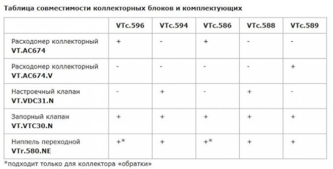
To ensure full compatibility of all underfloor heating units in the Valtec product line, you can select the manifold cabinet of the right size. It is characterized by increased depth and is designed to be placed inside collectors, pump-mixing modules and other elements of heating systems.
The Valtek cabinet is made of galvanized steel with an anti-corrosion enamel or polymer coating. Perforation is provided on the side walls, which is necessary for the pipe supplied to the collector to pass freely inside. The door has a lock.
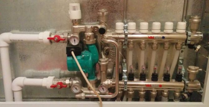
VALTEC pump-mixing unit
The inside of the cabinet has built-in rails to facilitate the installation of equipment on them. A dynamic frame is used to adjust the depth, and the retractable legs adjust the height.
Manifold cabinet for underfloor heating
Analyzing the advantages of this type of Valtec products, it can be noted that the cabinet has compact dimensions and is easy to assemble. It is safe for the surrounding atmosphere and easy to operate. Thanks to the clever fastening system, all strapping equipment fits inside. Access to each unit is facilitated, and there is no need to install additional security systems, since it is enough to close the cabinet with a lock.
Electromagnetic flowmeters
Connecting a warm floor to a thermostat thermostat
Their principle of operation is based on the law of electromagnetic induction, according to which an EMF is induced in an electrically conductive liquid passing through an electromagnetic field, which is proportional to the speed of the flow (conductor).
Such flowmeters have found application in volumetric metering systems for heat carrier and water at industrial and power plants. The disadvantage is the high cost and weight for diameters of more than 300-400 mm, the complexity of removal for verification.
Rod electromagnetic water meters operate on the principle of immersing the sensor in a liquid, where the flow rate is measured. Such meters determine the flow of cold water in completely filled pipelines.
The principle of operation of the flow meter. Installation and setup
When installing the collector and connecting the heating circuits of underfloor heating, the flow meter is placed on a collecting manifold, into which waste water flows. When the temperature of the coolant reaches the set value, a valve in the return part of the collector is triggered, narrowing or completely blocking the lumen for water flow. In order for the system to work according to the described scheme, the pump-mixing unit and the collector are equipped with thermostats.
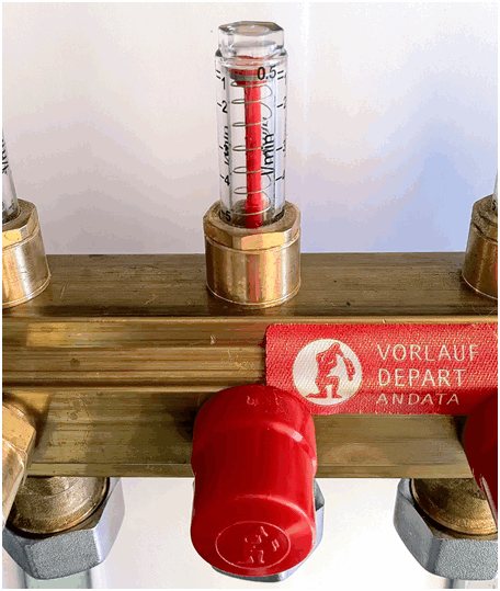
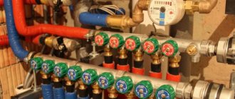
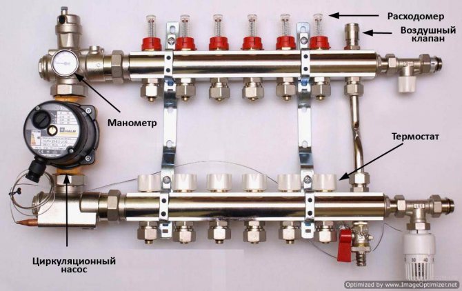
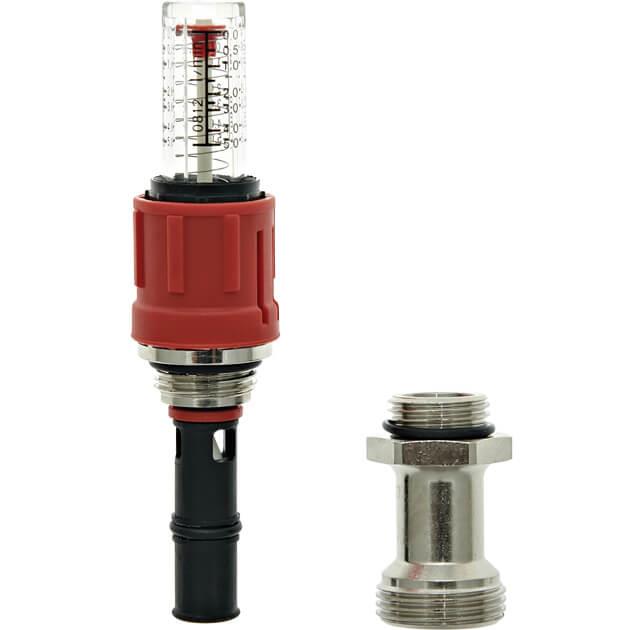
Flow meter flask with a scale for the flow rate of the coolant
In order for the water level in the transparent flask to coincide with the horizontal scale divisions, the device must occupy a vertical position. Therefore, for normal operation of the monitoring group, the collector should be installed using a plumb line or bubble level, achieving a strictly horizontal position of the equipment components. Installing a collector with deviations can cause the heating equipment to malfunction.
Important! Finishing the premises, installing a manifold cabinet can damage individual elements of the mixing group, therefore, the units and devices of the heating system must be located compactly.
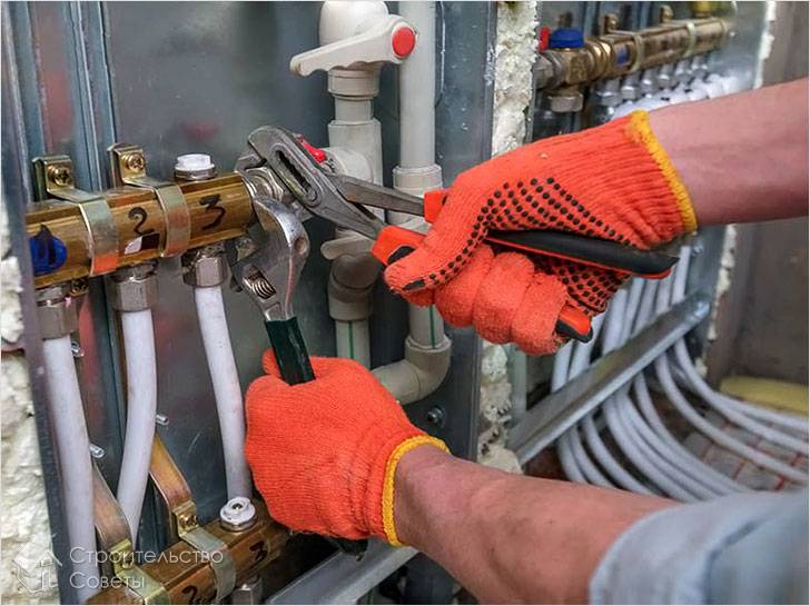
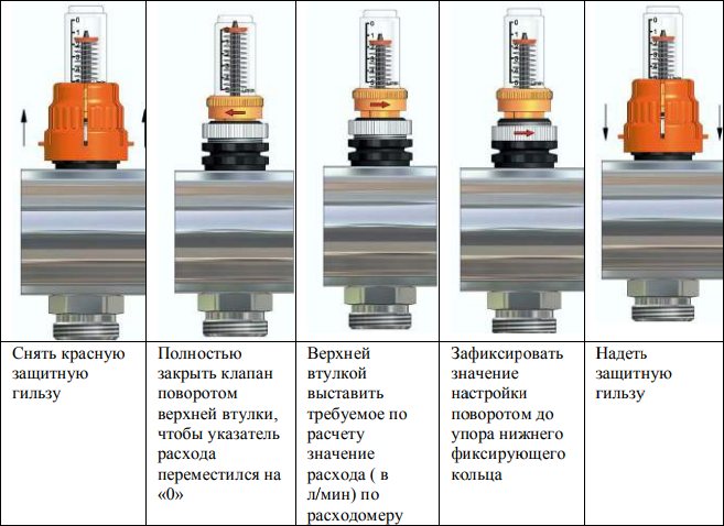
Installation and adjustment of devices is carried out in accordance with the installation and operating instructions, usually in the following sequence:
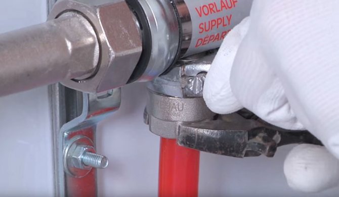
- using a wrench, screw the flow meter into the technological hole of the collector assembly part;
- by rotating the flow meter flask counterclockwise, prepare the device for operation;
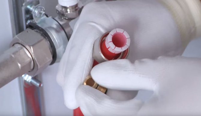
- dismantle the factory fuse (usually in the form of a ring);
- set the required pressure by turning the brass ring in the body clockwise to the desired mark - the location of the float will demonstrate the adjustment made;
- to prevent mechanical damage to the device, close the brass ring with a special plate;
- check the operation of the device as part of the entire heating system.
Selection, installation and adjustment of flow meters
Which electric boiler for underfloor heating is better to choose
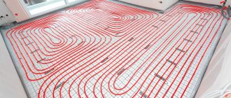
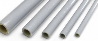
A water heat-insulated floor, as a rule, consists of several circuits of plastic pipes. Hot water, moving through them, gives off its heat and returns through the return supply part of the system. The collector (comb system) of the warm water floor is designed to collect cooled water, mix and supply heated water. In other words, it is a unit that controls the operation of the underfloor heating system.
To regulate the temperature, flow meters are provided in the manifold. These devices control the flow rate of the coolant, in this case water.
Why do you need a flow meter
Theoretically, it is quite possible to do without installation in the manifold of the flow meter. However, if you do not install this device, then:
- In different rooms, the temperature will be different;
- Excessive consumption of electricity for heating water in the system is possible;
- Different circuits will heat up unevenly.
A simple example can be given: a bathroom and a bedroom. A gas or electric boiler heats water in the same way for the bath and for the bedroom. But the bathroom is at least 3 times smaller than the bedroom.
Accordingly, it will be hot in the bathroom and cool in the bedroom with the same water supply to the underfloor heating system. This situation is due to the fact that the total length of the plastic pipes in the area is much larger in the bedroom.
It is in order to regulate a comfortable temperature regime in the entire apartment that the installation of such a device is desirable.
Advice! When installing a water-heated floor, you should strive to make the contours of pipes of approximately the same length. This will save energy costs and allow more accurate temperature control.
Principle of operation
The device is installed on the return collector taps. When a predetermined temperature is reached in the manifold valve system, the lumen of the energy carrier is narrowed or completely closed. This principle of operation is possible with full automation of the system. For this, the collector is equipped with a temperature sensor.
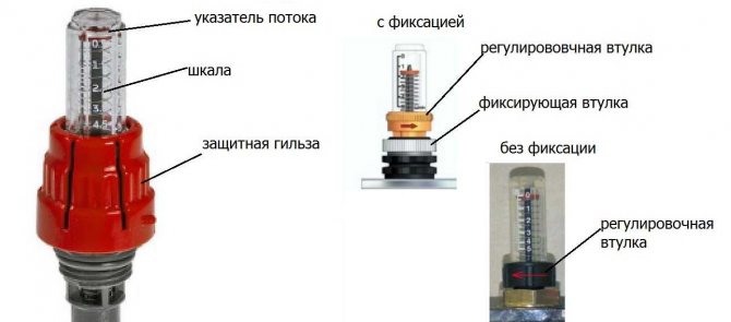
The flowmeter itself consists of several parts:
- Housing;
- Transparent flask with a scale;
- Float.
The flask is usually made of durable glass, the body can be plastic or brass. The float is located inside the flask, it serves as an indicator of the speed of the coolant. The flowmeter is also called a float flowmeter.
In the automatic collector of a water underfloor heating, the balancing of the coolant flow is carried out using a temperature sensor. If the latter is not provided, then the flowmeter can be adjusted manually.
Step-by-step instructions for installation and adjustment
H2_2
The rotameter is installed strictly vertically. To ensure that the liquid level in the flask is accurate, the collector itself is also mounted according to the level. If the manifold line is installed crookedly, the temperature control will be incorrect.
Since finishing works often take place after the installation of the collector, it is necessary to protect the unit and its components from possible damage. The best option is to make a niche in the wall for it or a special cabinet.
Installation and adjustment:
- Using a wrench, screw the flow meter into the process inlet of the collector return line;
- Turning the membrane (flask) counterclockwise, open the pressure meter;
- Remove the factory protective ring;
- Turn the brass body ring clockwise to the desired head. This is balancing the flow rate of an energy carrier. The float on the scale will indicate the set value;
- Close the brass ring with a cover plate. This must be done to avoid damage to the device, especially if the water underfloor heating unit is not closed in a niche or cabinet;
- Check system operation.
During operation of the assembly, the bulb remains open so that the level of the water float can be seen. If balancing is needed during operation, the diaphragm simply turns in the desired direction.
Choosing a flow meter for a water-heated floor
High-quality variable area flowmeters must be accompanied by a guarantee for 5-7 years of stable operation. It is recommended to select flowmeters with a brass body
You should also pay attention to the flask, it should be made of transparent glass with good visibility of the water level scale. However, there is an opinion that it is better to choose products with a membrane made of impact-resistant plastic.
When choosing a device, you need to take into account the area of the pipeline system
It is also important whether the node is automated or not. In the first case, balancing will be extremely rare, mechanized collectors require more attention.
A source:
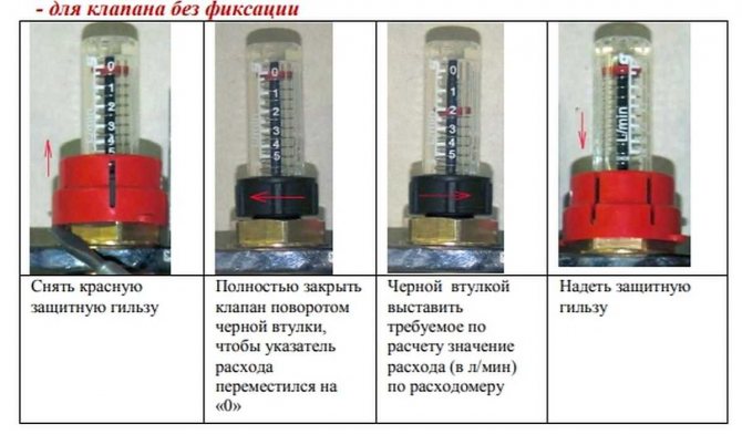
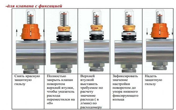
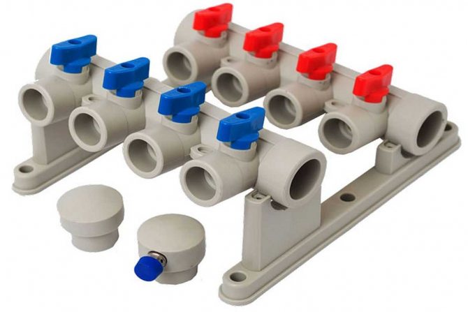
Features of customizing a Valtec manifold without flow meters
If the collector is not equipped with flow meters, but only valves, you will have to set the flow rate by touch. This is not figurative, but literal. Knowing the length of each circuit, on the longest one we open the flow to the maximum. We fasten the rest approximately. You can count the number of valve turns and be guided by them.
Collector for underfloor heating without flow meters
Next, we start the heating and wait for the floor to warm up. If there is a thermometer, we measure the floor temperature in the area of operation of each circuit. There is no thermometer - we feel and compare the sensations. Based on the results, we correct the position of the valves and again wait a few hours. We act in this way until the result is satisfactory. In principle, a Valtec manifold with valves without a flow meter is not that difficult to set up.
Evaluating the collector setting based on the return temperature
This check is based on the fact that with a correctly set flow rate, the return temperature on all circuits should be the same. For this type of adjustment or verification, special thermometers are needed. They are installed in the return pipe between the manifold inlet and the pipe.
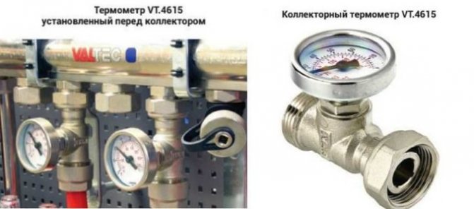
You can set up the collector using a thermometer on the return
The temperature of the longest circuit is taken as the reference - all the rest are adjusted to it. Only the adjustment results will need to be corrected after a few hours. When the floor heated by the controlled circuits warms up or cools down (depending on the regulation) and the temperature in the return pipe changes again. Several such settings will be required until the difference becomes insignificant.
If you decide to start installing a warm floor yourself, then you will inevitably face the question of how to connect it correctly so that it is efficient and heats the floor and the entire room. If you imagine the whole process, you can make sure that the key to the efficiency of the system is the correct connection of the underfloor heating collector, which is responsible for temperature control.
The manifold looks like an ordinary piece of pipe with several holes on one side that serve as outlets. A pair of such simple structures is actually responsible for the management of a water-heated floor. Let's figure out what these outputs are for and how to connect the underfloor heating collector.
Manual adjustment of the heating agent temperature
Temperature control methods will depend entirely on the equipment used. For example, if a system with a temperature controller and a servo drive is installed, then the setting is carried out according to the instructions from the manufacturer of this device. In this case, the adjustment is carried out in automatic mode. Now we will consider a manual method of setting the temperature using thermal heads.
Installation of thermal heads can be performed both for the supply and return of the coolant.
First of all, the system to the warm floor must be completely filled with coolant and free from air
But here it is important not to rush, otherwise air jams may form. If the connection was made from the boiler, then before starting the water into the heating circuits, turn off all the taps
After that, open the supply / return on one loop, filling it with a coolant. The air from it must escape through the air vent. Now turn on the circulation pump so that the coolant begins to move in this loop. At the same time, turn on the temperature on the boiler to 35 °. By touch, you should feel that hot water has flowed on the return and supply in the heating circuit. If everything is working properly, close this loop and open a new one. Using this method, you pump in and check each loop of the heating circuit. When you have set up each circuit, you open all the taps and adjust the required temperature by touch. In some hinges, the tap will need to be opened completely, while in others it is enough to slightly open it.
The coolant temperature in each circuit can be different. There are several reasons for this, such as the length of the loop. The shorter the contour, the faster it warms up and vice versa.
Thus, manual temperature control is carried out. It is enough to perform it once a year. But here it is important to take into account the nuance. The underfloor heating system is inertial. What does this mean in practice? If you have made changes to one of the hinges, you will have to wait a few hours to feel the clear changes in the indoor temperature.
If you have installed flow meters on the manifold, then the difference between the readings can reach up to 0.5 liters.


How the collector works
Water floors are laid in various ways, for example, concrete or floor, but regardless of the technology chosen, it is necessary to purchase and install a manifold cabinet.
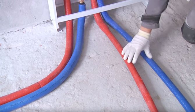
In the future, two pipes will be installed into it:
- supply, which leaves the boiler and supplies a hot coolant to the system; returnable, which performs an absolutely opposite role: it serves to collect water that has already been used up and has had time to cool down. It is returned back to the boiler and the process is repeated again.
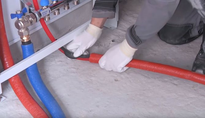
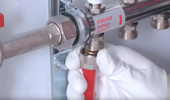
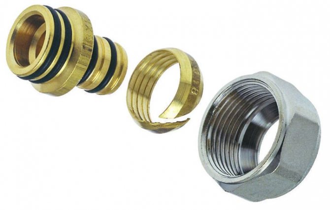
The cyclicity of the process is provided by another built-in component of the system - a circulation pump. One way or another, during the operation of a warm floor, say, during repair work, the system has to be turned off. For this, each of the pipes is equipped with shut-off valves. A plastic pipe and a metal shut-off valve are connected to each other through a compression fitting.Then a comb is connected to the valve, mounting an air vent on one end, and a drain valve on the other. After assembling the cabinet, proceed directly to the installation. And only with the comb installed on the wall can the pipes of the contour be cut along the length.
Combined heating scheme VALTEC
We would like to draw your attention to an example of a modern energy efficient heating system based on VALTEC equipment. It is designed for a country house or any other object with an autonomous heat source (boiler, etc.). The scheme provides for the combined use of traditional radiators and underfloor heating. This combination of technologies, as well as the applied automation make it possible to provide a high level of comfort at optimal costs for the purchase of equipment and its operation. The diagram uses and displays components from the current VALTEC assortment.
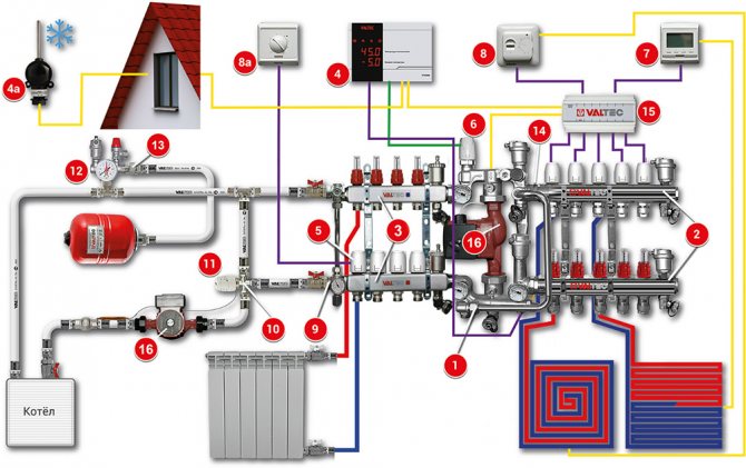
| № | vendor code | Name | Manufacturer |
| 1 | VT.COMBI.S | Pump-mixing unit | VALTEC |
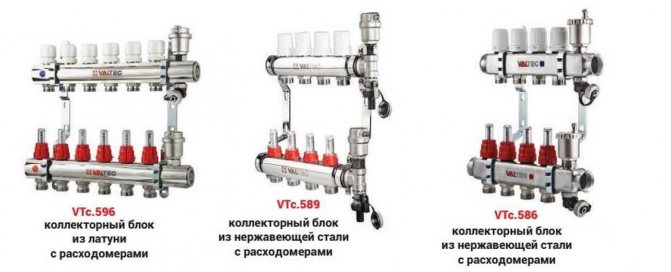
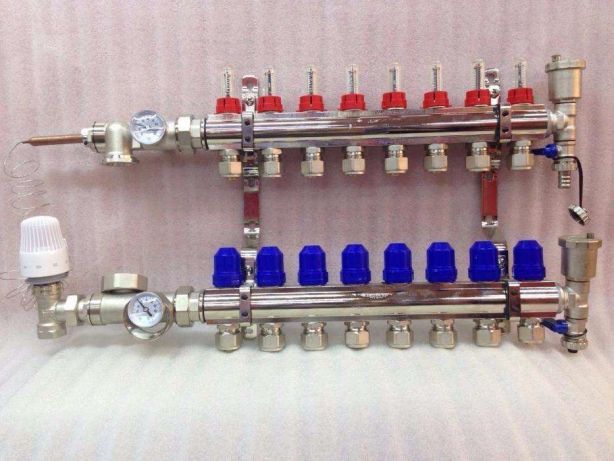
| 2 | VTC.596EMNX | Collector block with flow meters | VALTEC |
| 3 | VTC.586EMNX | Collector block made of stainless steel become | VALTEC |
| 4 | VT.K200.M | Weather-compensated controller | VALTEC |
| 4a | VT.K200.M | Outside temperature sensor | VALTEC |
| 5 | VT.TE3040 | Electrothermal servo drive | VALTEC |
| 6 | VT.TE3061 | Analog servo | VALTEC |
| 7 | VT.AC709 | Electronic room chronothermostat with floor temperature sensor | VALTEC |
| 8a | VT.AC601 | Room thermostat | VALTEC |
| 8 | VT.AC602 | Room thermostat with underfloor heating sensor | VALTEC |
| 9 | VT.0667T | Bypass with by-pass valve for circulating with closed loops | VALTEC |
| 10 | VT.MR03 | Three-way mixing valve for maintaining the return temperature | VALTEC |
| 11 | VT.5012 | Thermal head with remote attachment sensor | VALTEC |
| 12 | VT.460 | Security group | VALTEC |
| 13 | VT.538 | Squeegee-cutter | VALTEC |
| 14 | VT.0606 | Double manifold nipple | VALTEC |
| 15 | VT.ZC6 | Communicator | VALTEC |
| 16 | VT.VRS | Circulation pump | VALTEC |
Explanations for the diagram:
The use of the VALTEC COMBIMIX pump-mixing unit allows to link high-temperature circuits (heat source and radiator heating) and underfloor heating circuits with a low coolant temperature into a single system.
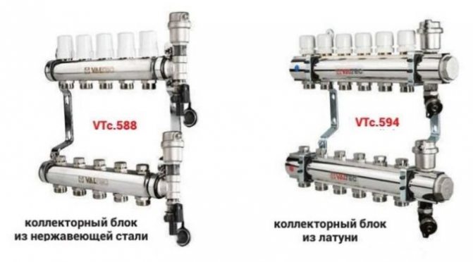
The distribution of coolant flows is organized using VALTEC VTc 594 (radiator heating) and VTc 596 (floor heating) manifold blocks.
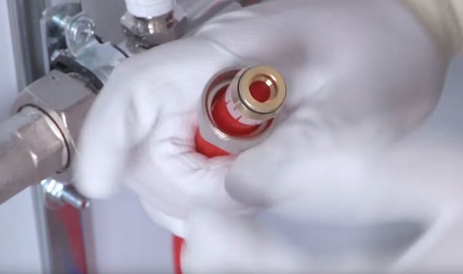
The distribution of the high-temperature heating system and the heating circuits are made of VALTEC metal-plastic pipes. The pipelines were installed using press fittings of the VTm 200 series; connection to manifolds - compression manifold fittings for metal-plastic pipes VT 4420.
Underfloor heating operation is controlled by a VALTEC K100 controller with a weather compensation function. Due to this, the temperature of the water in the underfloor heating circuits changes depending on the outside temperature, which guarantees savings in energy resources used for heating. The control signal from the controller is fed to the analog electrothermal servo drive of the control valve of the COMBIMIX assembly.
Thermal comfort in rooms with underfloor heating is maintained by a room thermostat VT AC 602 and a chronothermostat VT AC 709, equipped with air and floor temperature sensors. Through electrothermal drives, these automation modules control valves on the return manifold of the VTc 596 unit.
A thermostat with a remote temperature sensor VT AC 6161 is used as a safety thermostat. It stops the circulation pump of the COMBIMIX unit in case of exceeding the set maximum temperature of the heating agent in the supply to the underfloor heating circuits.
The heat transfer of the radiators is regulated by the room thermostat VT AC 601, which controls the valves of the VTc 594 manifold block using electrothermal servo drives.
The heat source circuit is equipped with a boiler safety group, a diaphragm expansion vessel, and VALTEC non-return and drain valves.
Ball valves of the VALTEC BASE series were used as shut-off valves.
Customization
You can set up the Valtec manifold manually, and it is also possible to do this automatically if the servo drives are installed on the supply.Carrying out this operation is necessary for the system to function in the specified mode in the future, as well as in order to diagnose possible malfunctions.
When setting up, you will need to perform several sequential operations in accordance with the instructions supplied with the product.
Exploded view of Valtec manifold
- The thermal head is removed.
- The overflow valve is set to 0.6 bar.
- The flow rate for the balancing valve located on the secondary circuit is calculated according to the method indicated in the instructions, with the result obtained on it.
- The pump speed is adjusted to determine the optimal water flow.

Scheme of a collector working with underfloor heating circuits - All connected branches are balanced. For this, the valve on the primary circuit is closed as far as it will go, and the balancing valves are opened to the maximum. Indicators are checked by flow meters. If in some branch they deviate from the norm, then the valve is tightened up to the required flow rate.
- The pressure of the bypass valve is set about 10% lower than that of the pump.
It remains to check during a test run the uniformity of heating of the underfloor heating circuits, as well as the difference in temperature of the coolant set by the manufacturer at the supply and return. If all setup instructions are followed, the desired heating efficiency and longevity of the entire system will be ensured.
Valtec underfloor heating collector for 2-4 circuits 20-60 sq.m.
Maximum heated floor area: 60 sq.m; Manual regulation. (For automatic regulation, it is required to additionally install a servo drive VT.M106.0.230 and a control thermostat or controller)
Specification
- 1 - Mixing valve MIX 03 3/4 "- 1 piece;
- 2 - Nipple adapter 1-3 / 4 "(VTr.580.N.0605) - 2 pcs;
- 3 - nipple 3/4 "(VTr.582.N.0005) - 1 piece;
- 4 - tee 3/4 "vn.-vn.-vn. (VTr.130.N.0005) - 1 pc;
- 5 - knee 3/4 "Nar.-Nar. (VTr.093.N.0005) - 1 pc;
- 6 - American 3/4 "(VTr.341.N.0005) - 1 piece;
- 7 - circulation pump with 1 "union nuts;
- 8 - ball valve 3/4 "vn.-vn. (VT.217.N.05) - 2 pcs;
- 9 - collector 3 / 4-1 / 2 "planks. (VTc.500.N.0502) - 2 pcs;
- 10 - collector connector 16-1 / 2 "(VTc.710.N.1604) - 4 pcs;
- 11 - connector with ext. threads. 20-3 / 4 "(VTm.302.N.002005) - 1 piece;
- 12 - connector with plank beds. threads. 20-3 / 4 "(VTm.301.N.002005) - 1 piece;
- 13 - collector tee (VTc.530.N.0500) - 2 pcs;
- 14 - automatic air vent 3/8 "(VT.502) - 2 pcs;
- 15 - drain valve 1/2 "(VT.430) - 2 pcs;
Connection
With the help of connectors (10), a 16x2 metal-plastic underfloor heating pipe is connected. The high-temperature circuit supply (boiler supply) is connected to terminal 16, and the boiler return is connected to terminal 17.
Valtec underfloor heating manifold with manual adjustment for 2 circuits. The hinges should be of approximately equal length for proper functioning. At the entrance and exit to the heating system 16, 17, it is advisable to mount American taps.
If 3 or 4 circuits are used in the above mixing unit for underfloor heating, then two collectors (9) are replaced by one variable collector (VTc.560n) and one collector with ball valves (VTc.580n).
Hydraulic leveling of a water-heated floor
We have a hot water heating system, which includes underfloor heating, arranged on the basis of a pump-mixing unit and a conventional collector with or without flow meters. It is a reliable, safe, comfortable and well-controlled underfloor heating system. In order for it to become such in practice, and not only on advertising brochures, it needs to be configured.
For a water floor in a private house, it is better to use collectors with flow meters, in this case it will be much easier to control the system. If you are reading this article, but you have a similar warm floor in an apartment or house with central heating, then pay attention to the maximum working pressure of the collector that you have chosen, usually for collectors with flow meters it is 6 bar. This may not be enough for the central system.
If you have servo drives on the manifold that are controlled by automation, then they will, if necessary, adjust the flow rate of the coolant. However, it will be necessary to preset the flow rate in the circuits.If you have a manifold without drives (in the overwhelming majority of cases), then such a setting is simply necessary.
The flow rate of the coolant through the circuit can be calculated using the formula:
Further, in order to obtain the required design flow rate of the coolant through the circuit, it is necessary to multiply the specific flow rate Gsp ((l / h) / m 2) by the floor area S (m 2) served by this circuit.
So, the easiest way to hydraulically level a warm floor is:
- calculate the water flow through each circuit by multiplying the floor area along which this circuit passes by 8.6; thus, we get the flow rate in l / h;
- turn on the floor heating pump, set the first speed on it (for an average private house);
- set the thermostatic head or mixing valve knob to about 30 o C;
- make sure that the water circulates freely through the branches and the air is expelled;
- adjust the kennel in such a way as to achieve the flow values obtained in paragraph 1 at each flow meter;
These actions will provide the so-called "pre-tuning". If everything is calculated correctly, then it will be quite enough. But in fact, during operation, the underfloor heating may need to be adjusted based on the feeling of comfort. When adjusting, it is necessary to understand that the circuits are hydraulically interdependent, "screwing" one can increase the flow through the other. You also need to be prepared for the boiler pump and floor heating pump to influence each other. This is not scary, but when the boiler pump turns on, it is impossible to adjust the underfloor heating, you need to wait until it stops.
Problems that may arise
Let's give a concrete example.
Difficulties in the installation of the system
The length of the contours in rooms of different sizes is different. This creates problems.
- The contour of the warm floor is installed in the bathroom, living room and kitchen.
- It connects to one collector.
- It is clear that the floor area in these rooms is different. Consequently, the length of the pipelines laid under the coating is also different.
- This means that the consumption of the coolant in them will also be different.
Note! In short heating rings, the level of hydraulic resistance of the tubes is lower. Based on this, water circulates in them faster than in long counterparts.
Consequently, at the same liquid temperature on the supply manifold, the floor will be overheated in some rooms, while in others it will remain cold.
The same situation can arise when using radiator heating circuits with a different number of sections and different pipe lengths, which are connected to the same storey collector. That is, some rooms will be overheated, while others will be cold.
To prevent this from happening, the instruction recommends determining the water flow in the radiator system by installing a thermostat on each battery. In fact, it is a valve that quantitatively controls the flow. Roughly the same can be done on an underfloor heating system.
Ways to solve the problem
It is possible to balance the heating circuits of underfloor heating systems that are connected to the same collector group in two ways.
- Applying the first of them, you need to make all the rings of equal length and correctly distribute them under the coating. For example, three circuits will be in the guest room, two in the kitchen and one in the bathroom.
- The second way is to mount only 3 circuits, according to the number of rooms. However, they will need to be connected not directly to the collectors, but through special devices - flow meters for underfloor heating, they are also called rotameters. By design, they are balancing valves.
In the given example, the term "flow meter" does not mean a measuring device, but a special tap, with which it is possible to control and set the consumption of the heat carrier.
It should be borne in mind that devices from some manufacturers can only be connected to a return manifold.
Optimal design of the manifold group.
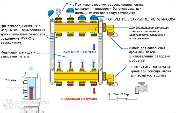
- The best option, when the manifold assembly has such a design, is that the supply manifold is equipped with a rotameter, and a thermostat is placed on the reverse analogue.
- Due to this, the supply part of the group directs a precisely metered volume of the heat carrier into each of the heating circuits. The return collector closes, opens the circuits, as the liquid cools down in the pipes.
- In addition, it is desirable that the supply manifold for underfloor heating with flow meters has an automatic air vent and is connected to the return analogue bypass having a bypass valve.
Note! Air that interferes with its operation is removed from the heating system through a vent. When it gets warmer outside, the thermostats close the circuits, at this time the bypass valve turns on and lowers the jumped pressure.
At the moment, manufacturers produce many flow meters, which are both measuring devices and regulators of the flow rate of the heat carrier. There are also devices that combine these functions. Naturally, their price is higher.
If you purchase only a measuring device, it will need to be installed together with an ordinary valve. By opening or closing the tap, according to the readings of the rotameter scale, you will be able to regulate the flow of the coolant.
How to balance heating circuits
An example of balancing a system.
- The total flow of the coolant through the collector (l / min) is taken as 100 percent.
- Further (also as a percentage), the consumption for each of the circuits is determined. For example - 15%, 35% and 50%. They are converted (proportionally) to liters per minute.
- Then you need to unscrew or twist the head of the rotameter (or a tap connected to a measuring flow meter), thereby setting the required readings.
- It should be borne in mind that only the calculated balancing of the circuits can be carried out in this way.
Assembling the manifold with flow meters.
- The actual adjustment is made according to the real flow rate of the coolant. For this purpose, a measuring rotameter must be installed in front of the supply part of the underfloor heating collector. Based on his readings, it will be possible to scatter the total costs along the circuits connected to the collector group.
Flowmeter functionality
A rotameter, or, if we give a complete definition to this unit, a float rotameter, at first glance, is an ordinary mechanical device. The design of the product is based on a plastic case (there are models made of brass), inside which a polypropylene float is placed. The body is equipped with a transparent bulb with a marking scale. Moving the float up and down inside the device indicates a certain value on the scale, by which you can judge the volume of the coolant circulating in the pipeline system - is it enough for the full operation of the heating circuits.
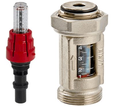
Traditional flow meter for underfloor heating collectors in various versions: on the left - in a plastic case, on the right - in brass.
From the point of view of theory, the heating system can work without this device. In this case, you will have to manually adjust the volume of water entering the circuit, based on personal feelings when the air temperature in the room changes.
On a note: by the sound of a working pump and by the intensity of heating of the warm floor, one can judge the degree of completeness of the supply of hot coolant to all heating circuits.
Refusing to use the flow meter when installing underfloor heating is fraught with the following problems:
- individual contours of the water floor will be supplied with a coolant without taking into account the characteristics of the room, as a result of which the temperature values of the floor surface of the heated rooms will differ;
- the consumption of the energy carrier used to operate the heating devices (electricity or gas) will be increased.
For example, you plan to heat a bathroom and a nursery at the same time. An autonomous gas boiler will heat water for the bathroom and the nursery in the same way, in the same temperature mode. However, the bathroom is smaller in size, and less boiler water is required to heat it than to supply a warm floor in a nursery. It is possible to achieve an optimal supply of heat carrier for warm floors in each room using a flow meter. Consequently, due to the operation of this device, it will be possible to achieve individual temperature values for comfort in the bathroom and children's room.
Assessing the operation and principle of operation of the device, the following conclusions can be drawn:
- the device operates completely autonomously, without requiring additional power supplies;
- the principle of operation of the flow meter allows you to create an optimal flow rate of the coolant for heating circuits, significantly reducing the energy consumption of heating devices;
- the design of the device provides visual control over the amount of water in the pipelines;
- the collector, together with the underfloor heating flow meters, greatly facilitates control over the operation of the entire system, is easy to install and unpretentious in maintenance.
Important! The installation of the device is carried out strictly in a vertical position, simply by screwing the device into a special socket of the collector. The device is fixed with a union nut.
On a note: When installing a warm floor, try to achieve the same length of heat pipes for all water circuits - despite possible differences in configuration, this greatly simplifies the regulation of the entire heating system and allows you to achieve optimal temperature parameters.
Time-pulse ultrasonic counters
The time-pulse method (or, in other words, the phase shift) is based on measuring the travel time of a signal against the flow and in the direction of fluid movement. To convert the ultrasonic signal, two or four piezoelectric elements displaced along the movement of water are installed on the pipeline. As a rule, disc elements are used, less often annular ones (for small diameters).
Piezoelectric elements can be installed inside the flow (on the inner walls of a pipe or channel) or outside the pipeline (in this case, the signal passes through the outer wall). Depending on the sensors used, the meters can be installed in gravity systems (both open and closed), as well as in completely closed pipelines with overpressure of the medium. There are such types of speed sensors:
- pipe - cut into the water supply from the outside. Can be used in pressurized and non-pressurized environments;
- wedge-shaped - installed on the bottom or inner wall of the pipe. As a rule, they are used in free-flow channels or in pipelines of large diameters, if the installation and maintenance of the sensor from the outside is inconvenient;
- spherical or hemispherical - mounted on inclined walls of open trapezoidal channels;
- sucker-rod - have the form of tubes, are installed on the vertical walls of the channels;
- overhead - contactless sensors, placed on the outer surface of the pipeline.
Depending on how the sensors are installed, a distinction is made between contact and non-contact devices. The advantage of non-contact portable flowmeters is the ability to install them on pipelines without breaking the integrity. They are rarely installed permanently, more often they are used for verification measurements at different points.
Pulse time meters are suitable for finding the flow rate of clean water or slightly contaminated water (with a small amount of suspended solids). They are used in water supply and wastewater disposal, in cooling circuits, in irrigation irrigation schemes, at pumping stations, in open natural and artificial canals and rivers. They are used for both commercial and technological accounting.
How to properly run underfloor heating
To put into operation underfloor heating, you must wait until the screed is completely dry. This can take up to three weeks. If time is running out, you can speed up the drying process by adding 1 degree of heat every day. This can be done only after 14 days.
Moisture should come out of the concrete evenly. Otherwise, the screed will begin to crack, and this will violate the integrity of the heating cake.
All heating circuit valves on the manifold must be fully open immediately before starting. The 3-way valve also opens to maximum. At the end, turn on the circulation pump. After this stage, you can start adjusting the temperature of the coolant.
Cross-correlation ultrasonic counters
These flowmeters work by the ultrasonic cross-correlation method. This technique is based on the principle of plotting velocities for different levels of flow, the meter makes it possible to build a real diagram of the distribution of velocities in the flow. The flow rate is also measured.
With water meters, ultrasonic tube and wedge-shaped velocity sensors are used, installed in the flow, the liquid level is determined using surface and underwater sensors. Execution of combined speed and level sensors is possible.
The meters are used in pressure and gravity, open and closed systems. It is an accurate measurement method that gives reliable results for streams of varying contamination levels, and is also effective in heterogeneous media. Flowmeters are used in technological pipelines, treatment plants, in rivers and reservoirs, etc. In large canals, several sensors can be installed across the entire width to obtain more accurate results.
Problem arising
- You install the contours of the warm floor in the bathroom, living room and kitchen;
- They are connected to the same collector;
- The area of the bath, kitchen and living room is clearly different, therefore, the length of the underfloor heating circuit will differ in each room, respectively, the flow rate of the coolant (water) will be different.
The problem with radiators can be easily solved, because the instructions say that by installing a thermostat on each battery, you can control the quantitative consumption. Typically, a thermostat is a conventional valve. Similarly, the problem is solved with the underfloor heating system.
By connecting underfloor heating circuits to the same collector group, you can balance them in two ways:
How the heating collector works.
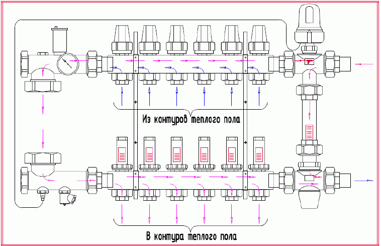
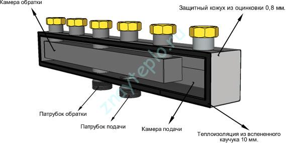
The most common horizontal balancing manifold is designed like this:
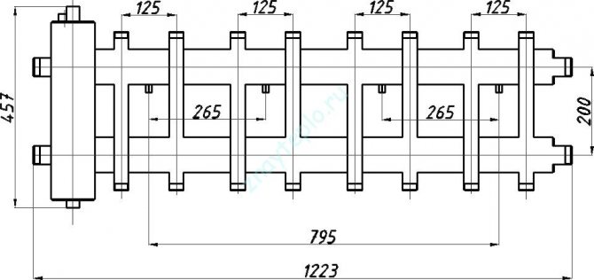
There are many different collector designs on the market today. The figure above shows a horizontal manifold with a hydraulic arrow, but there are vertical options for a similar design and it looks something like this:
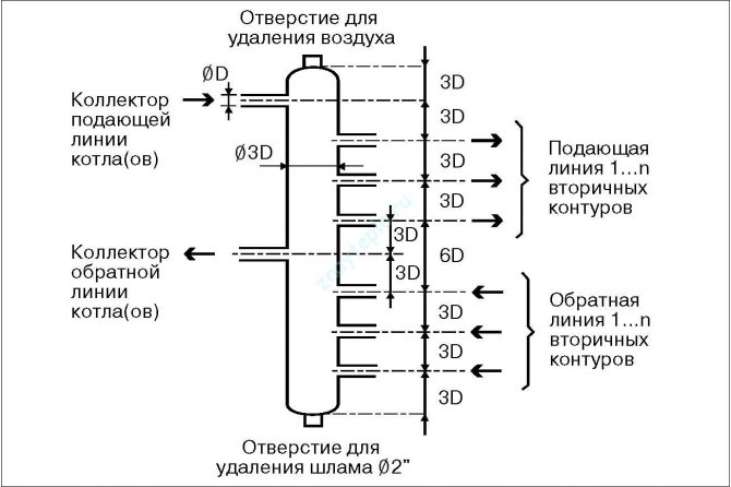
The essence here is similar to that implemented in the vertical design. But there is a slight difference in the piping. Here to whom, what is more convenient it is necessary to look at the place. Such a collector can be made from a large diameter polypropylene pipe. In this case, it is advisable to maintain the proportions indicated in the figure.
If you are cramped in space, then there is another very interesting design. It can be called coaxial:
Here, two pipes are inserted into one another. In this case, the hydraulic arrow can only be connected separately.
Okay, let's talk about collectors, and now let's look at a heating system based on it. Moving on!
Temperature equalization of a water-heated floor
With a water underfloor heating, you can regulate the temperature of the floor surface and the air temperature in the room. In those rooms in which, in addition to the heated floor, there are also radiators, it is better to provide the radiators with the opportunity to maintain the air temperature, and the warm floor will provide a comfortable surface temperature.
It must be remembered that the norms limit the surface temperature of heating structures, incl. for underfloor heating in rooms with constant presence of people (bedroom, living room, etc.), the surface temperature should not exceed 26-29 o C. In rooms with temporary residence of people (bathroom, corridor) - no more than 35 o C. In fact, often the residents of the houses violate these norms due to their lack of knowledge or inability to use the system. In addition, flooring manufacturers also have temperature restrictions. So, if you don't have tiles, then it's worth raising this issue and looking at the technical documentation for flooring.
The surface temperature of an underfloor heating depends on the temperature of the heating medium in the supply and return collectors, as well as on the flow rate and specific heat output, and, in particular, on the structure of the floor and floor covering. Let's highlight the main thing: with the following calculated or actual indicators, you need to be wary of an increase in the temperature of the floor surface above the norm:
- the water temperature in the supply manifold is higher than 45 o C;
- the calculated specific thermal power of the warm floor is more than 120 W / m 2
You can select your individual parameters for underfloor heating in the online program for calculating the warm floor. Fill in your original data and try experimenting with the metrics.
Doppler method
Meters using this method measure the difference in wavelength reflected from a moving stream relative to the wavelength of the emitted signal. Measurement of the received and transmitted signal to determine the difference between them is carried out using wedge-shaped or pipe velocity sensors installed at the bottom of the channel or pipe.
Doppler-based water meters are used in pressure and gravity systems, fully and partially filled pipes, open channels. They operate in streams of varying degrees of pollution (except for pure water). Doppler flow meters are used for commercial metering in pipelines and gravity canals, for measuring flow rates in rivers and canals of irrigation systems, in storm sewers, at pumping stations, pipelines for water intake and discharge into water bodies.
Adjustment features
For each individual room, there is a separate adjustment of the rotameters. The control is carried out according to the scheme of the installed circuits. This takes into account the level of heating of the liquid and the pressure.
It is recommended to perform balancing according to the following instructions:
- The total amount of the coolant passing through the collector in one minute is determined. Indicators are taken in liters. The resulting value is taken as 100 percent.
- The percentage flow rate of each individual water circuit is calculated. The result is converted to liters per minute.
- The flow meter adjusts the amount of liquid supplied to the pipeline.
By doing this, you can carry out a long-term correction of the water circuit. To indicate the actual parameters, it is necessary to observe the indicators of the flow meter. According to observations, it is possible to accurately determine the flow rate of the circuits connected to the collector.
Manifold with flow meters for underfloor heating
The flow meter is adjusted depending on the installed model.After connecting the device to the manifold, a preset should be made by setting the initial position, which allows access to liquid.
In flowmeters without a built-in valve, an additional shut-off device is used to set the "open" position. In this case, balancing is performed during the operation of the system.
Combined flow metering devices can be preset using full turns of the built-in valve. Each turn reduces the clearance by the set value.
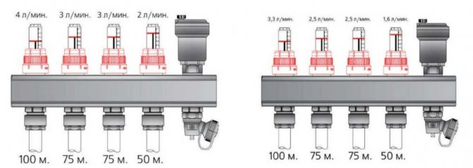
The adjustment of the floor heating flow meter is carried out taking into account the control of the fluid velocity in one minute - from 0.5 to 5 liters.
Before you start adjusting the flowmeter, you should check the condition of the installed circuit. Pilot testing is necessary to exclude the presence of leaks in the circuit, which can cause distortion of readings in the device.
The flow meter is an essential element in a multi-circuit floor heating system. The device allows for an even flow of fluid into all individual pipelines. In order for the heating equipment to function as efficiently as possible, it is necessary to choose the right flowmeter, as well as carry out its installation and adjustment in accordance with the technical requirements.
For the average person, the underfloor heating system does not look complicated, just pipes with hot water laid inside the screed. In practice, this is not at all the case. Due to the special requirements and mechanics of work, a collector group for a warm floor is necessarily present in the piping system, which distributes the coolant and provides regulation of the microclimate in each room.
Outcomes
It is important to ensure that when the underfloor heating system is operating, the flow rate on the manifold is visible. This is necessary for maintenance. Each water circuit must have its own flow meter.
We recommend: How is the installation of an infrared underfloor heating performed?
As you can see, in the equipment, each element performs its functions, therefore, each must be given sufficient attention, and in order for the entire system to work as a whole, it is worth equipping it with a flow meter and a collector, which will evenly distribute all the heat.
- Similar posts
- How to put polystyrene foam for underfloor heating?
- How to install a warm floor without a screed?
- How does the floor heating automation work?
- How to lay underfloor heating under linoleum?
- How to check underfloor heating?
- Features of the Korean underfloor heating
Valve selection criteria
A three-way valve in the manifold allows you to maintain the desired coolant temperature
If the circulating pump regulates the flow rate of the working fluid, then the control valve limits the fluid according to temperature. An autonomous boiler produces a heat carrier with a temperature of 95 degrees. In the heating system, the water is not much colder - 80-90 degrees. The normal temperature of the liquid in the heated floors is 35-55 degrees. The regulating thermostat determines the temperature of the flow of the working medium and gives the command to the valve to open the opening from the return stroke. With cool water, the temperature drops. When the temperature in the pipes reaches 55 degrees, the circulation pump is disconnected from the network by a thermostat, after which the volume of the passing heat carrier decreases.
The 3-way valve is a unit with 1 outlet and 2 inlets. The valve plug is opened by a temperature sensor located in the valve.
When choosing a valve, the following indicators are taken into account:
- The volume of the room for heating. Small rooms do not require complex automation units. Balconies, toilets, corridors work easily under the supervision of the simplest devices. Heating large areas requires an automatic valve with a built-in diaphragm opening temperature sensor.
- The volume of the liquid to pass through.This indicator is determined when writing a project for a heating system. The valve must meet the fluid flow requirements. Otherwise, it will fail.
- Cross-sectional diameter for connection to heating pipes. Adapters are used at different rates.
- Manufacturing material. Quality valves are made of bronze or brass - materials with a small expansion coefficient. They do not change their properties when in contact with a hot coolant.
The three-way valve is a tricky part. It is necessary to choose reliable models from well-known manufacturers. Warranty, specifications, certificate, test report are verified upon purchase.
Before installation, the valve must be checked - the minimum value of the temperature of the control ring is set and a stream of hot water is passed. A serviceable valve must shut off this flow.
Heating of residential buildings with two or more floors involves the use of several water circuits of different lengths. The combination of a three-way valve and a servo drive with a controller allows you to supply hot coolant to a specific room or send it for heating.
Initially, the heating servo is not included in the package. But the presence of a servo motor allows you to adjust the temperature depending on the time of day.
For a valve with an electric motor, the actuators are electromagnets or low-power servomotors.
The main types of collectors
Stainless steel manifolds last longer than brass or metal
The scheme of operation of the device is as follows - water from the boiler enters the storage tank. Such a tank is located at a height above the "comb". The coolant enters the distributor with shut-off and control valves. From the distributor, the streams diverge in separate branches. The outlet pipes are assembled at the bottom of the "comb" to be sent to the boiler for heating.
Usually, the unit is a piece of pipe with a certain number of bends. As the technical task becomes more complex, the complexity increases tenfold, the complexity of setting up the automation, installation becomes much more complicated.
Stainless steel
Collectors made of stainless steel are stronger than brass ones. They have a large flow area that equalizes the pressure of the flows of different heat carrier consumers. The Valtek manifold for heating is designed for an average of 50 years of operation at a pressure of 10 atm. and temperatures up to 130 degrees.
Branded models are reliable - even the appearance of a welded seam does not lead to corrosion. Buying models from cheap manufacturers, you can run into low-quality metal and surface corrosion.
Made of polypropylene
The polypropylene manifold can be assembled by hand from pipes and fittings
Polymer comb is made of polypropylene pipes. This lightweight material is not as durable as steel, but it will successfully serve for more than one year. Plastic manifolds are extremely cheap. The use is justified when the coolant is circulated in several heating devices. If the main task is to save money, this option is suitable.
The stores offer models with fittings and manifolds with slam-shut valves.
To switch to a metal product with a thread, combined fittings are used.
Plastic combs are common in Ukraine. To strengthen the structure, up to 30% fiberglass is added to PA66 polyamide in factory-made technopolymers to increase strength.
The disadvantage of polymer products is thick walls. They reduce the cross-section of the passage with the same size of the part. Steel assemblies are stronger, the walls can be made thinner - the internal section increases and passes several percent more liquid per unit of time under the same conditions.
Another disadvantage of polymers is oxygen permeability. Fiberglass reinforcement keeps it to a minimum. But oxygen diffusion is present.
The advantages of polymer products are resistance to aggressive media, electrochemical corrosion, low thermal conductivity. For the same tube length, the polymer loses less heat than steel or brass.
Brass
It is recommended to buy brass manifolds with nickel plating.
This material is the leader in the manufacture of combs. For production in Europe, a hollow brass rod is made. For decades, products have been made from it - cut to the required length, drilled holes for flow meters, valves, and cut threads. Stamped models are also present on the market.
Due to rising prices for brass, manufacturers switched to cheaper materials - steel and plastic. However, brass models are still preferred. They have one drawback - zinc leaching. But it is leveled by chrome plating or nickel plating of the surface.
In low-temperature conditions, the advantages of small expansion of brass are leveled and are relative.