| Fig. one ... Position of axonometric axes. |
The Uniform Requirements for the Execution of Construction Drawings states the following:
"... the diagrams of the systems are performed in an axonometric frontal isometric projection on a scale of 1: 100 or 1: 200, the nodes of the circuits are on a scale of 1:10, 1:20 or 1:50."
The position of the axonometric axes is shown in Fig. 2.
It is allowed to use frontal isometric projections with an angle of inclination of the y-axis of 30 ° and 60 °.
Frontal isometric projection is performed without distortion along the x, y, z axes. The determination of the position of the axes is shown in Fig. one.
System diagrams are performed in axonometric frontal isometric projection on a scale "- says paragraph 3.2.1 of GOST 21.602-79. In the educational literature on construction drawing, they explain: “axonometric schemes are performed in frontal isometry with a left axis system and a distortion coefficient along the axes, conventionally taken as a unit, which makes it possible to use a metric scale when constructing.
ORDER OF PERFORMANCE OF THE TASK
Internal cold water supply design
The design of the water supply of a residential building is carried out in accordance with the requirements of SNiP 2.04.01-85 and SNiP 2.04.03-85.
2.1.1 Internal water supply
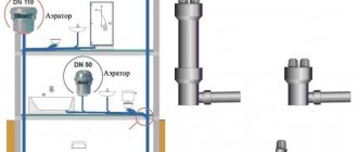
The water supply system includes the following elements: input, water meter unit, internal water supply network (distribution mains, risers, connections to water taps) and installations for increasing the water pressure in the network.
2.1.2. Selection of the system and circuit of the internal cold
Plumbing
1. Depending on the initial data, the following internal water supply systems of buildings are possible in the work:
a) an internal drinking water supply system powered directly from the city network without booster devices (H gar
2. There is only one input for a building with a dead-end network of an internal water supply system, since a temporary interruption of the water supply is allowed.
The entrance to the building is laid in its central part with a slope 0,005 from the building and connected to the water supply network with the help of a nurse. It is designed from cast iron plumbing pipes d = 32 mm according to GOST 5525-61.
The length of the bushing should be as small as possible, and the diameter of its pipes is determined by calculation. Input length ℓ
= 15 m
(the pipe is sealed in the place of its passage through the building foundation using a metal sleeve d = 250 mm and inserts in the annular gap of the resin strand and oily mint clay). At the point of connection of the input to the external network, a well is provided for placing the connecting and shut-off valves.
The depth of the bushing is assigned depending on the depth of the pipes of the street water supply network and the depth of soil freezing.
The inlet is laid with a slope from the building above the drainage pipes and away from them at the distances recommended by SNiP 2.04.01-85.
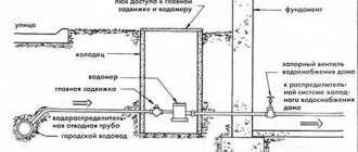
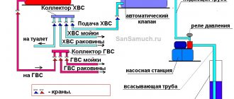
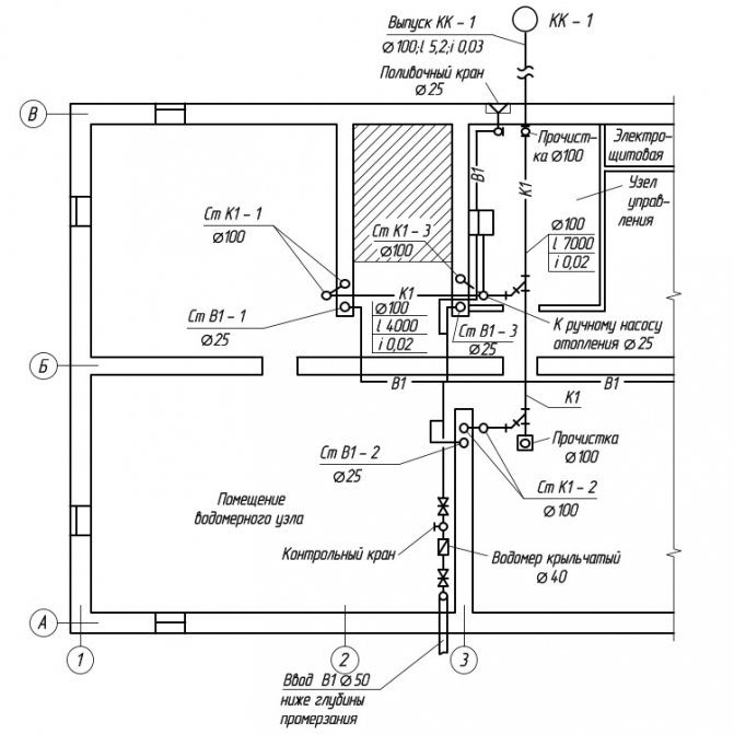
3. The water metering unit and water meters are located near the outer wall, immediately after the pipes are introduced into the building, in the central part of the basement, where the temperature is 2 ° C. The selected area is available for inspection, meter reading and on-site repair.
In internal water supply systems, as a rule, high-speed meters are used: vane or turbine. Vane meters are installed horizontally only; turbine - in any position. On each side of the meter, there should be straight pipe sections on which valves or valves are installed.
A drain valve should be installed between the meter and the second (according to the water flow) valve, valve.If there is one entrance to the building, a bypass line is arranged at the meter with a valve, sealed at the usual time in a closed position. The device of the water metering unit is shown in Fig. 2.
Fig. 2
... Water metering unit and its main elements.
1
- water meter (water meter);
2
- locking device to the water meter;
3
- shut-off device after the water meter;
4
- control and drain valve;
5
- a sealed gate valve on the bypass line;
6
- bypass line;
7
- main pipeline.
2.1.3. Internal water supply network device
When designing a water supply network, you need to strive for the shortest length of pipelines. The main line is laid under the basement ceiling with a slope 0,002 towards the water metering unit. On the main line, in places of concentration of sanitary devices (in sanitary facilities), 5 risers are installed, necessary for distributing water across the floors of the building.
An open laying of risers is provided. Leads to water taps and appliances are laid 0.25 m above the floor.
Shut-off valves are installed at the base of each riser; on each connection to the toilet cistern; on branches to each apartment; in front of external watering taps. The internal water supply system provides for two watering taps, one for every 60–70 m of the building perimeter, located in the niches of the outer walls of the building.
The internal trunk network, risers and connections to devices and watering taps are designed from galvanized steel gas-supply pipes GOST 3242-75.
Risers are located in the bathrooms.
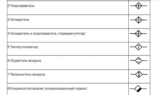
How to reflect all communication elements in the drawing
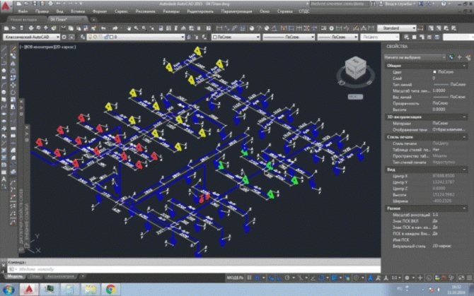
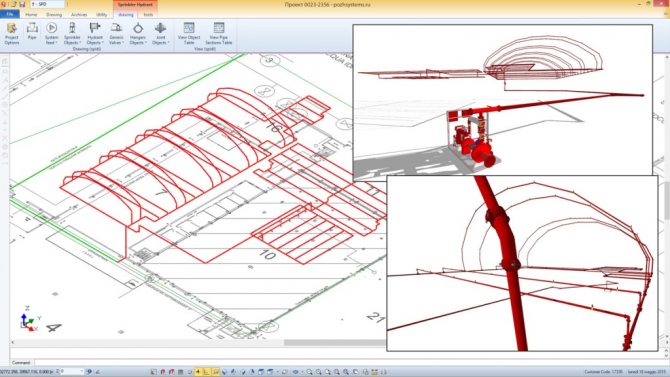
In order to cope with such a task, you will need a program for creating graphic drawings, sketches and diagrams. You can open any of the arsenal of building programs supplemented with such a function, or the one with which you are familiar.
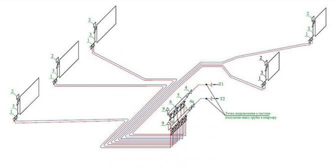
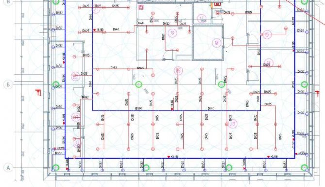
Before developing a perspective view, prepare a plan for a building, apartment or other room with communication networks.
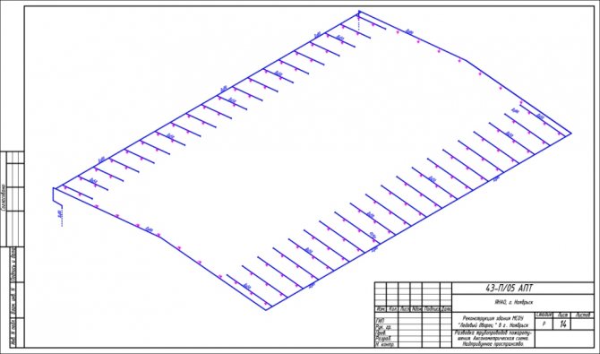
Drawing everything is not that difficult, especially if you have experience with engineering programs. The sketch reflects all the pipes shown on the plan of the house. They are transferred to an electronic version of the axonometric diagram and reflected at an angle of 45 degrees.
Important! This rule does not apply to horizontal sections. The lines are left unchanged.
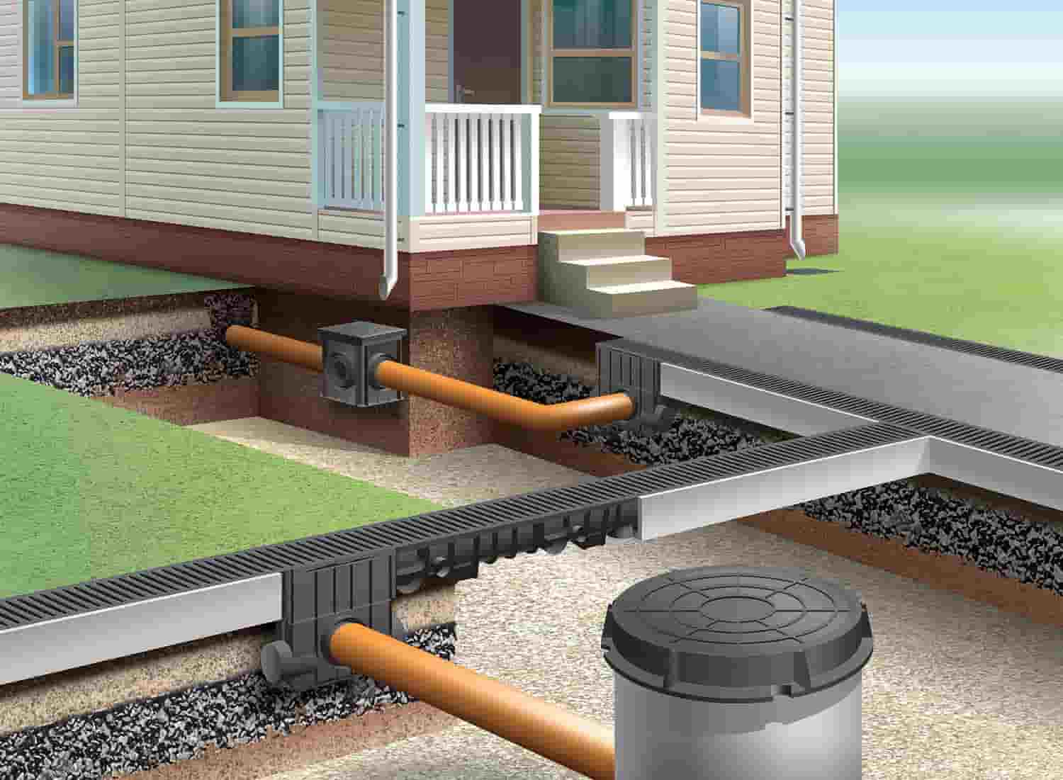
Outdoor sewerage
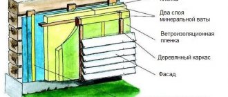
Plastic pipes are also used to equip the outer part of the sewer system. They are laid in a trench, the depth of which exceeds the depth of freezing of the soil (in more detail: "External sewerage device - installation options"). The bottom of the trench is covered with a dense layer of sand, after which pipes are laid out on it (here you need to remember the need to observe the slope). Inspection hatches must be installed at the pipe connections. It will not hurt to install a check valve in the pipeline, which will prevent the return of wastewater to the internal sewer network.
How to display structural elements electronically
The fastest way to build a drawing is by cloning the entire schematic. To do this, select the "Insert" command, after which the integrated image is inverted. In order for the function to be executed, it is given a value of 45 degrees (a number is written in the program).
Having prepared the basis in the electronic version, where the risers are marked on the plan, they put symbols in the form of dots. A vertical line is drawn to reflect all floors in the building. For the purpose of better perception, the floor panels are reflected in the diagram.
Important! Don't make the slabs too long. Take advantage of the gap.
The peculiarity of the axonometric sewerage scheme is the reflection of all elements of sanitary devices: urinals, toilets, sinks, ladders and other devices for carrying out hygiene procedures.

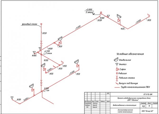
What is reflected in the diagram?
In the axonometric drawing of the sewage system, they must show:
- Piping entrances inside the house.
- Distribution system wiring in the building (risers and branches from them to each floor).
- Locking and regulating valves.
- Reducing rings for pipes with different diameters at their joints.
- Descent points from the system (tees with plugs).
- Cranes: watering and fire units.
- Sewerage equipment, water measuring points, control and measuring devices and other components of the sanitary and water supply line.


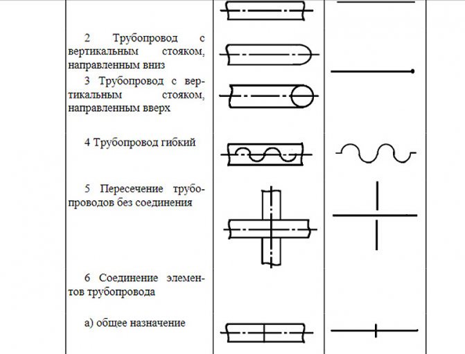
Axonometric diagram - pipeline
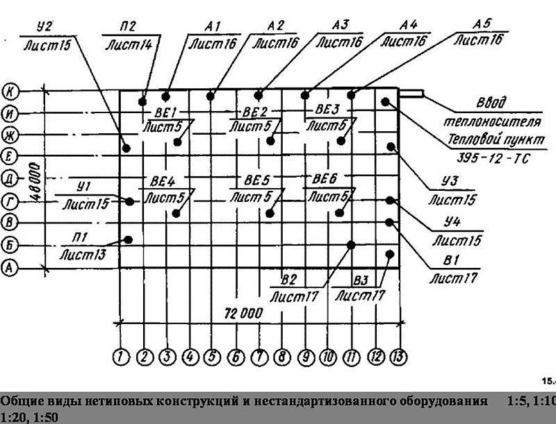
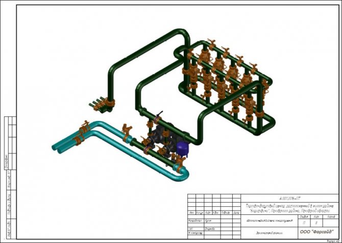
| Installation drawings of the OGUR work place, and view. |
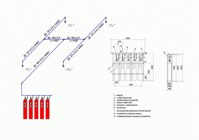
The axonometric diagram of pipelines is not drawn to scale, but in compliance with the approximate proportionality of all pipelines included in it for clarity of the image.
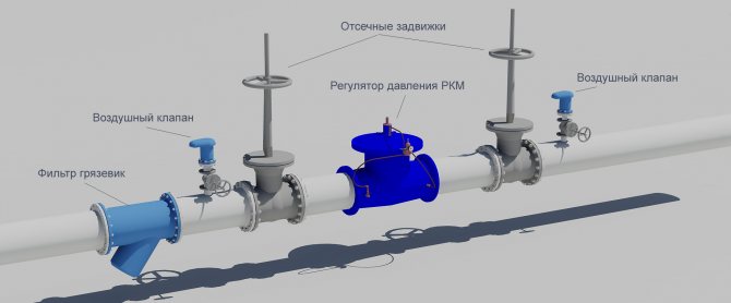
On the axonometric diagram of the pipeline, which is usually used as executive detailed drawings of pipeline lines, the following should be indicated: diameter and wall thickness of the pipes; the location of supports and suspensions, welded joints, indicating the brands of the welders performing these joints; location of fittings, blow-off and drainage devices; numbering of points for observation of creep.
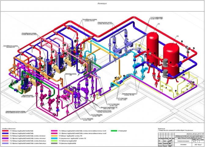
| Axonometric diagram of the pipeline, block, columns, condensers and cooler - 5 nodes. |
For each axonometric diagram of the pipeline, a consolidated bill of materials is drawn up, which indicates the consumption of pipes, smooth and welded bends, fittings, flanges, transitions, plugs, fasteners and gaskets.
What is depicted on axonometric diagrams of pipelines.
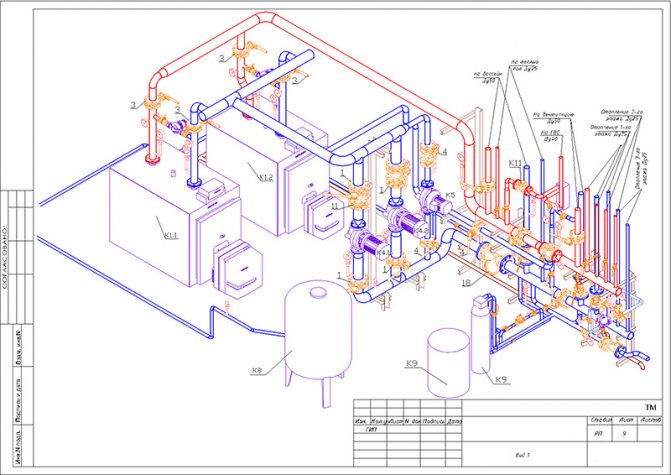
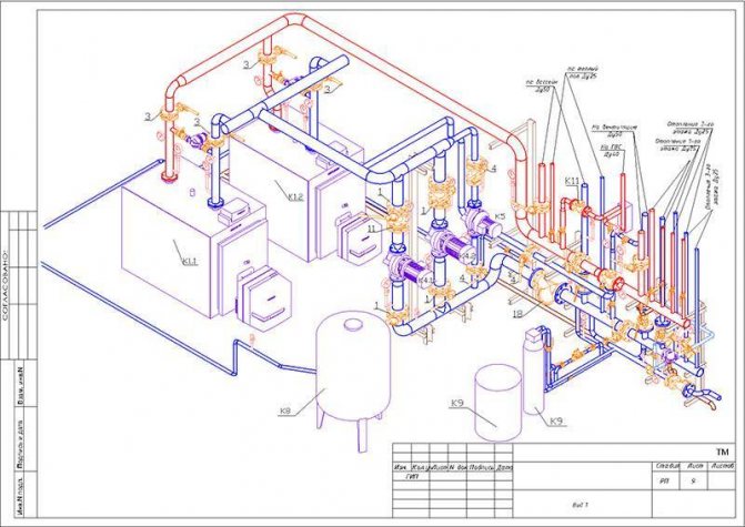
The passport is accompanied by drawings of the boiler room (melt, longitudinal and cross sections), and for hot water boilers, in addition, an axonometric diagram of the boiler room pipelines.
The passport is accompanied by drawings of the boiler room (plan, longitudinal and cross sections), and for hot water boilers, in addition, an axonometric diagram of the boiler room pipelines.
The passport is accompanied by drawings of the boiler room (plan, longitudinal and cross sections), and for hot water boilers, in addition, an axonometric diagram of the boiler room pipelines.
| Residential building plan with water supply and heating network inputs. |
Drawings for sanitary devices in buildings are drawn up on the basis of general architectural and construction drawings - plans of facades and sections and contain floor plans with the application of pipelines and equipment, the necessary sections, axonometric diagrams of pipelines and air ducts, riser diagrams, individual nodes and parts and other drawings ...
Gosportekhnadzor of the USSR, to which the organization performing their installation presents: a pipeline passport containing data on its operating parameters, survey results, etc .; certificate of manufacture of pipeline assemblies; axonometric diagram of the pipeline.
To register the pipeline, the installation organization submits to the local authorities of the USSR Gosgortekhnadzor: a pipeline passport containing data on its characteristics, operating parameters, and survey results; certificate of the quality of production of assembly units of pipelines; certificate of the quality of pipelines installation; axonometric diagram of the pipeline.
To register a steam and hot water pipeline, the installation organization submits the following documentation to the local authorities of the USSR Gosgortekhnadzor: pipeline passport containing data on its characteristics, operating parameters, survey results, etc .; certificate of the quality of manufacturing of pipeline assemblies; certificate of the quality of the installation of pipelines; axonometric diagram of the pipeline.
Blueprints should be clear and clear, and for imported installations there should be drawings with Russian translation.The layout of the technological pipelines of the turbine hall is drawn in a perspective view. Before starting the installation of the refrigeration unit, axonometric piping diagrams are posted in the engine room, which are used for installation, commissioning and start-up of the system.
What data is entered into the drawing
The introduction of the following indicators describing the water supply system is mandatory when constructing an axonometric diagram. This information includes:
- The designation of the risers (usually the area of the leader line).
- The level of the floor of each of the floors of the room, the border of the horizontal branch (at the axes of the pipeline), the height of the draw-off points (marks along the risers).
- Diameters of system elements.
- Slope angles of pipelines (with indication of the slope index).
- Dimensions (length) of each of the independent sections of the pipeline, which include risers and horizontal branches in millimeters.
- Coordinating dimensions (information of a secondary nature).
- Designation of nodes for the purpose of detailing the drawing.
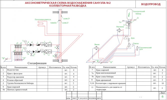
In addition to a number of basic data, accompanying documentation is attached to the diagrams, including a specification for materials and equipment.
Axonometry of water supply, heating, sewerage
According to GOST 2.317-2011, all axonometric diagrams related to sanitary systems of water supply, sewerage, heating are built in frontal dimetric (oblique) isometry with a left coordinate system.
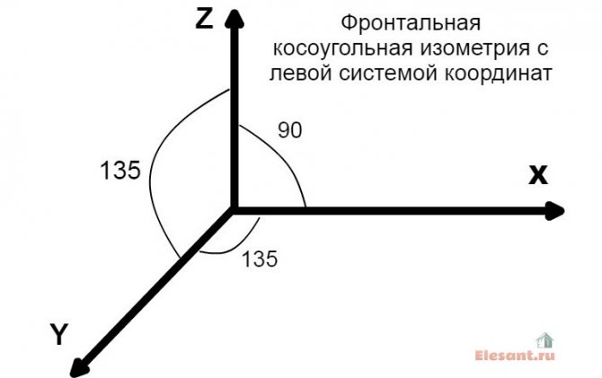
Accordingly, the dimensions along the z and x axes will be without distortion, and along the y axis by half.
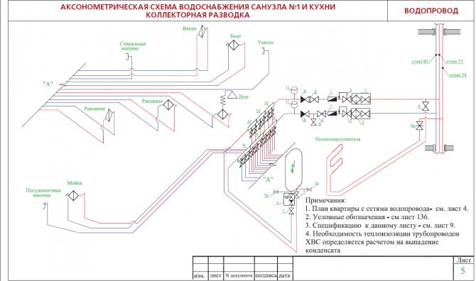
What does this drawing have to do with pipes and plumbing, you ask? Now imagine that the planes along the axonometric axes are the walls of your house or apartment. Plumbing pipes, water supply lines, sewerage and heating pipes run along the walls, vertically or horizontally. This means that we can draw pipe paths in axonometry without showing the walls themselves.
This will give very clear drawings of how and where to install the plumbing wiring. Moreover, plumbing fixtures are applied to the axonometric diagram in symbols, pipe diameters are applied, explanations are made, tables on materials and equipment are compiled for the diagrams. As a result, you have in your hands a detailed guide on how to install plumbing fixtures in a house (apartment), practically eliminating installation errors.

Features of sketch design
Here attention is focused on the reflection of the devices. If one element climbs onto another, and this happens in most cases, then a dotted line is drawn, indicating the displacement of the plumbing element in order to improve the visual effect.
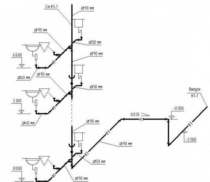
The axonometric diagram of the water supply system should include readings of all pipe diameters. If the toilet bowl is not marked on the outlet, then a diameter of 50 mm is taken, if there is one, the minimum diameter should be 100 mm. These numbers are important to remember. For risers, in 90% of cases, an indicator of 100 mm is used. Slopes in a similar diameter will be 0.02, with an indicator of 50 mm, an angle of inclination of 0.03 is set.
If you have already applied all the elements, mark the outlets, the diameter of which is larger than that of the risers, the number of 0.02 is taken as the slope.
At the last stage of drawing up the axonometry, special marks are made based on the characteristics of the site and the construction plan. Here they note the level of freezing of the soil, the location of the foundation, as well as other factors affecting the edits.
Axonometric diagram
| Working drawings of pipeline assemblies. |
Axonometric diagrams and working drawings of technological pipelines assemblies, as a rule, are developed for objects with a large number of pipelines and complex technological wiring, for pipes with a nominal diameter of 50 mm and above.
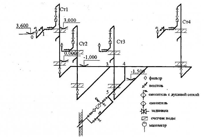
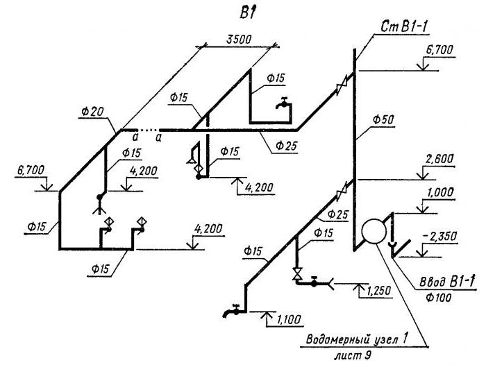
Axonometric diagram of the gas pipeline (Fig.51) complements plans and sections and represents a network of pipelines drawn without walls. The diagram is usually drawn without a scale and therefore cannot be used to calculate pipe lengths. The scheme specifies the direction of the pipelines relative to the plan and section, specifies the pipe diameters. According to the scheme, they get an idea of the entire network, the position of valves, parts and the interconnection of elements.
Axonometric diagrams give a visual representation of the location of water supply pipelines in buildings, the diameters of pipes and the direction of their slopes, the location of transition couplings, shut-off valves, gate valves, taps and other fittings on pipelines, as well as the places where water is drained from water supply systems.
| Axonometric diagram of a complex pipeline node (frontal oblique isometry. |
Such axonometric diagrams are fairly easy to perform; however, they are very useful in supporting complex piping assemblies and in avoiding design errors.
| Sewerage network plans. |
Axonometric diagrams of sewer networks are not made, but cuts are made along the sewer pipes that feed each sewer riser. In fig. 228 shows a drawing of a section through the sewer pipes of the sewer riser KS-P.
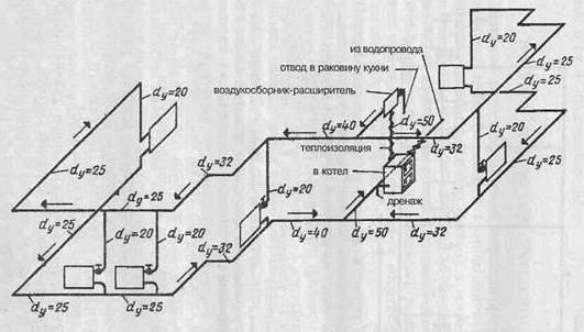
Axonometric diagrams of the supply and return pipelines (upper and lower wiring) are shown in Fig. The diagrams show shut-off valves, gate valves, transition couplings and an air collector, and the pipe diameters in millimeters are indicated. The slopes of the pipes are indicated by arrows. The main riser ends with an air collector that collects air from the heating network.
If axonometric duct diagrams are available in the project, they should not be drawn up again. In this case, it is advisable only to make the necessary adjustments to the design schemes, due to the measurements made.
An example of an axonometric diagram of an exhaust ventilation system of a VZ carpentry workshop of a training and production plant is shown in Figure 18.29. The system provides suction from three machines and floor. Dust fan of type TsP7 - 40 No. 5, version B with a power of 7 5 kW ensures the operation of the system, discharge of sawdust and shavings into the cyclone of type Ts-800, and air into the atmosphere.
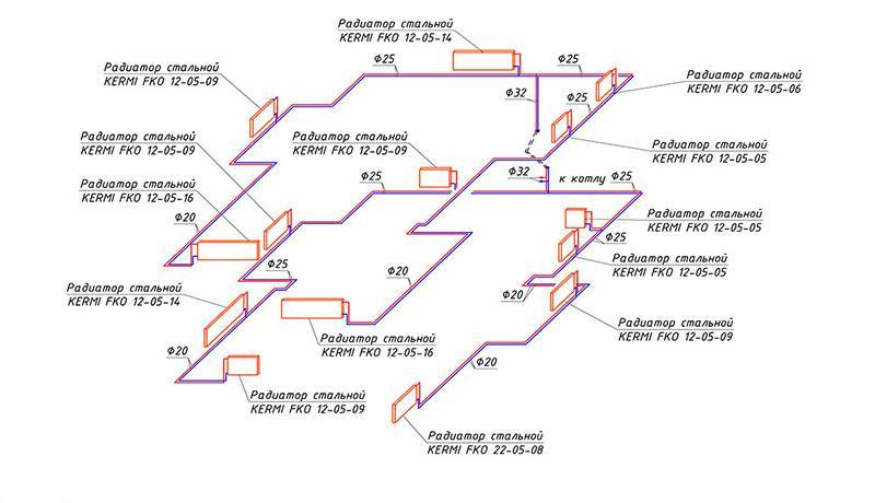
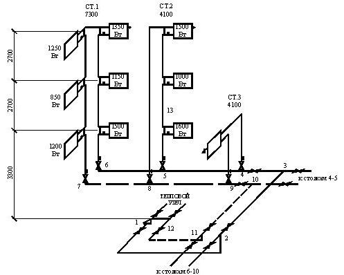
An axonometric diagram of the network is drawn with circulation pipes drawn on it. At the same time, in residential buildings with a number of floors up to 4 inclusive (if floor-heatsinks are not designed), only main circulation pipes should be provided; in all other cases, circulation is also done in risers.
| Plans I (a and II (b floors, basement plan (c and attic plan (d with drawing elements of the heating system) (Roman numerals in circles are the numbers of risers. |
Draw a basic axonometric diagram of the heating system. The uprights that shade the drawing can be moved out, and the goal is shown in the diagram.
According to the axonometric diagram and Appendix 3, the coefficients of local resistances are determined for each section. Local resistance refers to that of the adjacent areas where the air speed is greater.
Features of drawings
When drawing up an axonometric diagram, pay attention to the following points:
- Plumbing and other devices connected to the risers and the distribution network are reflected only when there are no necessary diagrams in the attached documentation.
- The zero mark (the level of the first floor) is shown on the risers by drawing a thin horizontal line. In the case of detailing the project, each of the nodes of the drawing is considered separately, reflecting it on an enlarged scale.
- If necessary, the sketches of diagrams and drawings of water supply networks and sewerage systems include symbols for shut-off and control valves, watering taps and other elements of systems.
What data is indicated when drawing up a diagram
The diagram of the water network of the building indicates:
- image and marking of risers;
- the place where the pipeline is connected to the building;
- floor branch of the wiring;
- shut-off and control valves;
- the height of the level of the location of plumbing fixtures;
- dimensions of pipeline sections (in mm);
- floor marks of all floors;
- water meter unit in the basement;
- watering taps.
On the diagrams, using the leader, the diameter of the pipes is indicated, the nozzles that are used when changing the dimensions of the wiring. It is necessary to note the places of water discharge, fire hydrants, instrumentation.
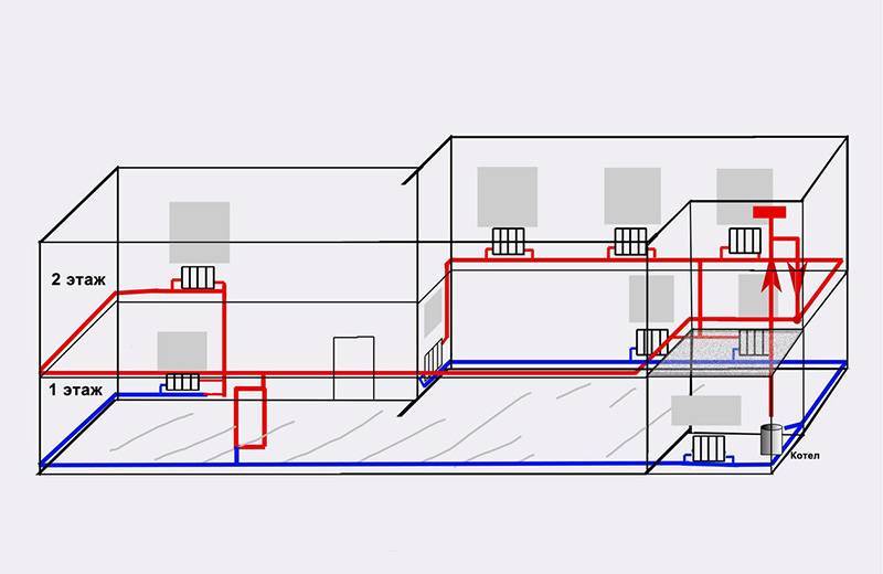
Axonometric drawings of heating and ventilation branches
When working with utility networks, calculations and graphic visualization are important components of work on a project for the construction of a residential building. In addition to the plan of the house and its facade, the package of documents required for construction is complemented by an axonometric communication diagram. On it, you can visually study a particular network: plumbing, heating, ventilation. The use of such drawings is especially important when arranging complex systems. The presence of a perspective view of the heating project simplifies the work of installers in the process.