Regulating valve.
This valve is similar to a pressure reducing valve. The control valve has a special actuator, usually pneumatic or electric, connected to an automatic regulator. The control unit is a device that measures fluid flow, temperature or pressure and compares them to the required level. The control unit issues a command by which the desired position of the working body is established. The movement of the working body in the control valves can be translational or rotational; structurally, they are most often of the valve or throttle type. Control valves are widely used to regulate pressure or fluid flow. Such a valve is rarely fully closed or open. In the control valve, flow throttling occurs, which is accompanied by a pressure drop. In this regard, such a valve must have a high resistance to the erosive effects of the fluid flow. A drop in pressure can lead to cavitation in the liquid and noise in gas or vapor flows (cm.
CAVITATION). Special designs of control valves with increased cavitation resistance and low noise have been developed. Control valves operate in more adverse conditions than most other valve types.
Control valves: tackling the toughest challenges
Regulation of the parameters of the flow of the working medium is necessary for the effective control of technological processes and the interconnection of their individual phases. Without this, it is impossible to ensure stability in nominal modes and the normal course of transient modes.
Controlling the parameters of the flow of the working medium by changing its flow rate, providing a set of requirements for the type of control characteristics, reliability and accuracy of regulation, is one of the most important tasks of pipeline valves. And, above all, ─ control valves, which occupy an extremely important place in the general nomenclature of pipeline valves.
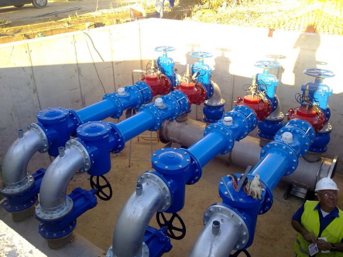
Control valves, both in their "classical" form, and in combination with shut-off valves (according to "GOST 24856-2014. Pipeline valves. Terms and definitions") provide conditions for the normal operation of equipment at various facilities, including such complex and responsible as thermal power plants, NPP, pipeline transport systems. An example of the symbiosis of various types of pipeline fittings is a shut-off and control valves (shut-off and control valve) that combine the functions of shut-off and control valves. As you know, shut-off valves are designed to shut off the flow of the working medium with a certain tightness.
Sometimes control pipeline valves are classified as independent from the friction point of the classification established in the regulatory and technical documentation (This was the case in "GOST R 52720-2007. Pipe fittings. Terms and definitions" does not mention pressure reducing valves), reducing (throttle) valves designed to reduce (reduce) the operating pressure in the system by increasing the hydraulic resistance in the flow path. That is, a pressure regulating valve. The relevance of control valves only increases as the operating conditions in the power industry become more complex.Their striking manifestation is an increase in the initial parameters of coolants at thermal power plants and an increase in the unit capacity of turbine plants in the nuclear power industry.
Without the use of control valves, it is impossible to meet the growing requirements for ensuring the reliable and at the same time the most economical operation of various systems in the heat and power industry, pipeline transport and other areas of modern technologies.
Drain and safety valves.
Safety and drain valves devices for automatically reducing pressure in closed vessels when it reaches a dangerous limit. These valves are used in a wide variety of technical devices from coffee makers, pressure pots and boiler heating systems to power plants, where pressures reach 30 MPa, and power hydraulic systems, where pressures can reach 70 MPa. There is a certain difference between safety and drain valves. The safety valve is a special type of spring-type drain valve that is designed to open momentarily in order to release a large amount of steam or gas at once and then close again abruptly. Drain valves are used to communicate with the atmosphere in liquid systems, and relief valves in high pressure gas and steam systems.
The drain valve opens slightly when the pressure in the vessel reaches a set (low) value and slowly increases the release of fluid as the pressure rises. The drain valve is usually used where it is undesirable or not necessary to release large volumes of the working fluid.
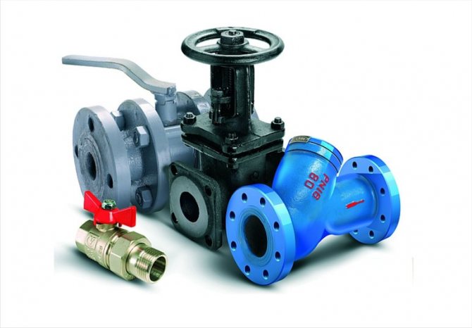
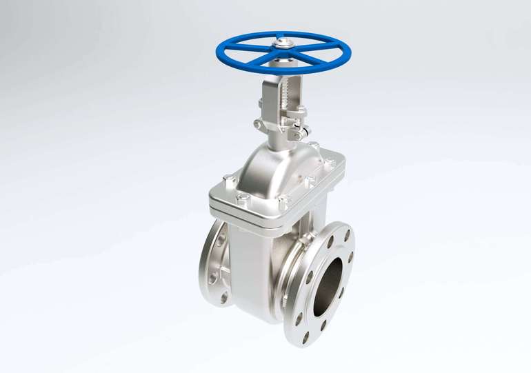
Gate valve.
Gate valves (gates) are commonly used in industrial piping systems where the valve must be either fully closed or fully open. This valve is called a shut-off valve. When the valve is open, the flow passes with little or no resistance. In the dampers, the damper is lowered in the guides. In double-seat gate valves with a wedge, the discs are pressed against the seats due to their wedging when the stem moves. In valves with stem rotation, the lower end of the stem is screwed into the valve; rotation of the stem causes the valve to rise and fall. In lift-stem valves that take up more space in the open position, the top of the stem is threaded and the handwheel is a nut with thrust washers. The nut moves the stem as the handwheel turns.
Valve selection recommendations
Due to the fact that flanged valves are widespread, their selection should be approached with extreme care and scrupulousness. If the device is chosen incorrectly, there is a possibility that it will soon fail. There are several key parameters to consider when buying a tool:
- the material from which the body is made;
- type of shell;
- a kind of drive mechanism.
Valves, the body of which is made of steel, are durable and durable, but it is recommended to install them on pipelines through which steam, gas, oil products or water are transported. The advantage of alloy steel is that it is able to withstand low ambient temperatures, reaching 60 degrees below zero.
Stainless steel valves have a high resistance to corrosion, as well as resistance to aggressive chemical elements. Stainless steel flanged valves are widely used in the food industry, since it is necessary to maintain high purity of the medium that is transported through the pipeline. Cast iron parts have low resistance to environmental factors, and they are also fragile and have a solid specific gravity. It is recommended to install just such mechanisms on water supply systems.
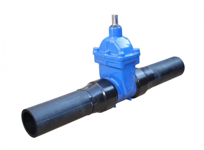
When buying a shut-off valve, you need to take into account the design of its body, which can be all-welded or collapsible.The size of the part and the ability to carry out one or another type of repair work will depend on the design. All-welded parts have a one-piece body, which does not provide for the possibility of carrying out revision measures, therefore, such a valve should be installed in those areas where regulation of the flow of the medium is extremely rare.
This precaution is necessary in order to prolong the life of the device.
The design of the gasketed valves consists of individual parts that can be replaced if necessary if any of them becomes unusable. It is due to the fact that the valve is disassembled that it can be used to carry out any type of repair work, but such a tool is distinguished by its high cost.
Depending on the particularities of the process, a flanged valve with a suitable control mechanism can be selected. The simplest drive mechanism for flanged valves is a handle, with which the valve is moved to open or closed mode. When choosing a valve for regulating the flow of thick substances, it should be taken into account that the handle must be strong and made of durable materials.
Another common type of drive mechanism is a gearbox, which must be installed on pipes if their cross section is more than 300 mm. The stem is set in motion by means of a flywheel, which begins to rotate when the toggle switch is switched. Automatic devices are represented by pneumatic and electrical control systems, with which you can control the valve even from a distance. Such devices contribute to the most efficient regulation of all technical processes.
Classification of valves
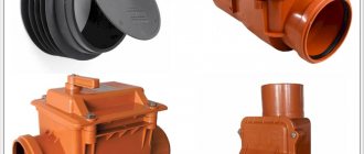
The shut-off type check valve is often referred to as “anti-flood” because of its main function of preventing fluid from leaking out. On the market of valves of shut-off type, valves of various designs are distinguished, depending on the place of their installation, as well as the functions performed.
Shut-off valves are classified by design features into:
- corner;
- checkpoint;
- with one seat for the shut-off device;
- two-seat.
By the method of closure, disposable shut-off devices are classified depending on the method of cutting off the flow of the contents of the pipeline into:
- devices in which the overlap is carried out by means of a load effect;
- valves closed by a spring mechanism;
- units with a pneumatic drive;
- devices with an installed electromagnetic valve.
Each type of shut-off valves is selected and installed only with the help of qualified specialists who are well versed in the configuration and purpose of one or another element of pipeline systems. Automatic or mechanical valves can have different purposes, which directly determines the scope of use of this valve.
Protective devices for pneumatic drives
Multi-circuit brake drives are characterized by the autonomy of each circuit, which is manifested in the preservation of their operability in the event of depressurization or failure of one or more circuits included in the drive. In pneumatic multi-circuit drives, the autonomy of the circuits is carried out by means of safety valves - triple, double and single.
***
Double safety valve
The double safety valve (Fig. 1, a) serves to distribute the compressed air coming from the compressor over two circuits and maintain pressure in one circuit if the other is damaged. The compressed air from the compressor, passing the pressure regulator and the anti-freeze safety device, enters the central cavity and, pressing two flat valves, passes through the outlet to the auxiliary brake system circuit, and at the same time,through another outlet - to the circuit of the parking and spare systems of the tractor and trailer.
If an air leak occurs in one of the circuits, for example, connected to the right outlet, then the central piston together with the right plate valve will move to the right under the influence of air pressure in the left outlet and press against the thrust piston (the valve remains closed). As soon as the pressure in the central cavity is greater than the spring force of the first stubborn piston, the right plate valve will move away from the central piston and excess air will escape into the leaky circuit. The same will happen in the event of an increased air flow rate in one of the circuits. If one of the circuits is damaged, the double safety valve maintains a pressure of 0.52 ... 0.54 MPa in the other circuit.
***
Triple safety valve
The triple safety valve (Fig. 1, c) distributes the air coming from the compressor over three autonomous circuits and, if one of them is damaged, maintains the pressure in the serviceable circuits.
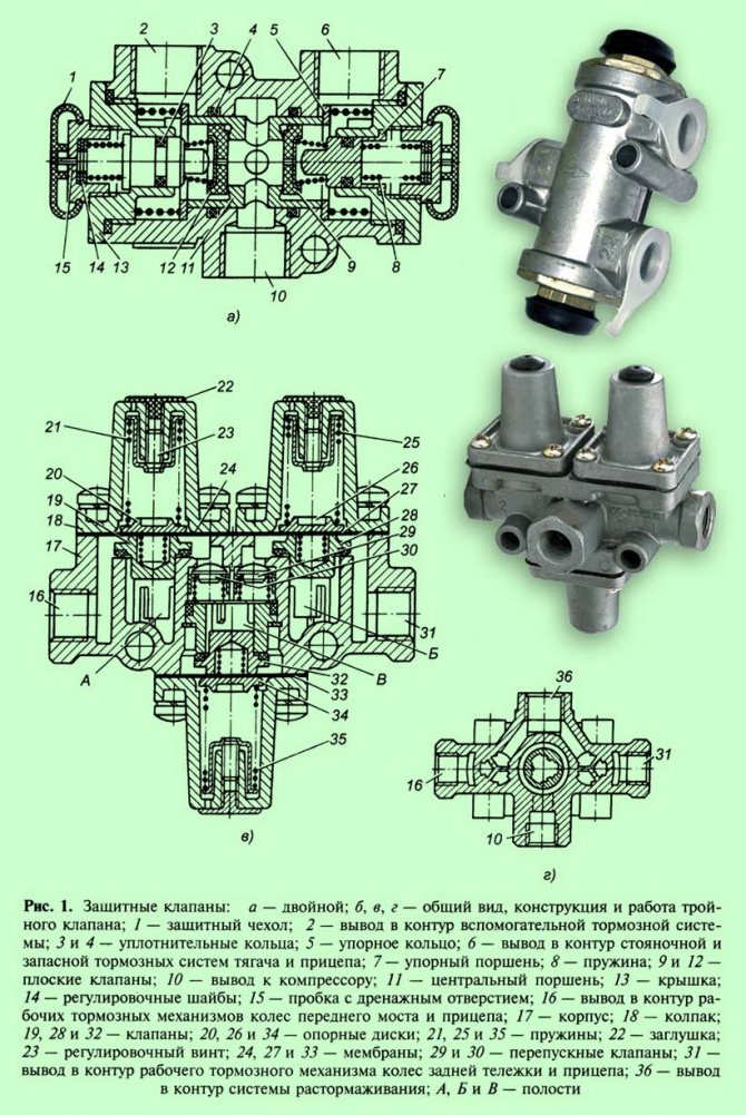
Compressed air from the compressor enters the left and right cavities and, when the pressure rises to 0.52 MPa, it opens the left and right valves, overcoming the resistance of its springs. Bending the left and right diaphragms, the compressed air enters through the outlets into the circuits of the working braking mechanisms of the wheels of the front axle and trailer, as well as the wheels of the rear bogie and trailer. At the same time, compressed air opens the left and right bypass valves, enters the central cavity and at a pressure of 0.51 MPa, opening the central valve, passes through the outlet into the circuit of the release system.
When one of the circuits is depressurized, the pressure in the associated cavity of the safety valve will decrease and, under the action of the spring, the valve of the damaged circuit will close.
If the supply line from the compressor is depressurized, then all valves will close under the action of their springs and the pressure in the circuits will remain.
***
Single safety valve
A single safety valve (fig. 2) is used to connect the two circuits of the brake system and ensure their independent operation. Its functions include maintaining the pressure in the receiver of the tractor in the event of an emergency drop in pressure in the trailer line, and protecting the trailer from spontaneous braking in the event of a sudden drop in pressure in the receiver of the tractor.
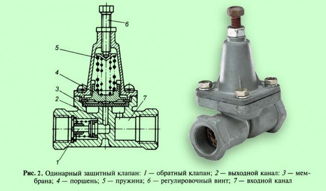
At a pressure of 0.55 MPa, compressed air entering through the inlet channel, overcoming the resistance of the piston return spring, lifts the membrane and passes into the outlet channel, and from there it enters the trailer supply line through the check valve.
When the pressure in the inlet channel drops below 0.545 MPa, the piston return spring returns the diaphragm to its place. The check valve prevents the compressed air from the supply line from entering the outlet channel under the diaphragm.
***
Academic disciplines
- Engineering graphics
- MDK.01.01. "Car device"
- Section map
- General device of the car
- Car engine
- Car transmission
- Steering
- Brake system
- Suspension
- Wheels
- Body
- Vehicle electrical equipment
- Fundamentals of car theory
- Fundamentals of technical diagnostics
- Fundamentals of hydraulics and heat engineering
- Metrology and standardization
- Agreecultural machines. Agreecultural equipment
- Fundamentals of Agronomy
- Transportation of dangerous goods
- Materials Science
- Management
- Technical mechanics
- Tips for a graduate student
Olympiads and tests
- "Engineering graphics"
- "Technical Mechanics"
- "Engine and its systems"
- "Car chassis"
- "Electrical equipment of the car"
Materials.
Valves are made from a variety of materials: gray cast or ductile iron, bronze, carbon steel or stainless steel, and nickel-based alloys such as Monel and Inconel.These materials vary in cost, operating temperature range, and corrosion resistance and are listed in ascending order of cost. Gray cast iron is suitable for most non-critical applications, especially in plumbing. Bronze has high corrosion resistance and is used for corrosive environments. Carbon steel is durable and can be used at high pressures. Chrome-molybdenum steel is characterized by heat resistance and is used at high temperatures (about 600 ° C), for example, in heating plants. Stainless steel and nickel alloys have higher corrosion resistance than bronze and high heat resistance. CORROSION OF METALS; METALS MECHANICAL PROPERTIES.
Valves made of these materials are used at pressures from less than 0.5 MPa (urban water supply systems) to 70 MPa (hydraulic drives). The operating temperature can vary from 255 ° C (liquid hydrogen) to 800 ° C (gas turbines). Cheap materials such as gray cast iron are sometimes coated with epoxy for corrosion protection.
The internals of the valve can be made from the same materials as the body, but plastics, rubber and reinforcement coatings are also used. Typically cotton, Teflon, rubber, or graphite are used as sealing materials to seal the seat, stem and plug, depending on the medium and temperature. Sealing materials must provide good sealing and at the same time low friction to ensure free movement of the stem.
Specifications
The main technical characteristics of control valves that are needed to select and connect them to the piping system are:
- Nominal bore diameter;
- Locking type;
- Type of fixation on the pipeline: flanged or threaded. Welding devices are less common;
- Range of changes in the state of the working environment. Maximum and minimum temperature and pressure at which the control valve remains operational;
- Valve body and sealing surfaces;
- Control type: manual, pneumatic, hydraulic and so on.
The installation of control valves is carried out mainly on systems that require accurate distribution of the flow of the working medium, most often these are heating systems. Also, control valves are widely used in industry, when transporting liquid and gaseous working media.
If you need control valves for heating and heat supply, please contact the professionals by calling toll-free 8-800-77-55-449 or by e-mail on the website www.gardarikamarket.ru
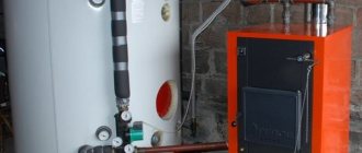
DRIVES
Valves usually have one or the other actuator. The simplest actuator is a linear valve handwheel or swing arm. Special devices such as a gear train can be used to rotate the handwheel. Power hydraulic or pneumatic drives are often used. These actuators can generate significant forces required to move valve stems in high pressure or remote locations, or to operate multiple valves from a single console. Spring diaphragm valve actuators typically use compressed air. Compressed air moves the diaphragm with the stem in one direction, and the spring in the opposite direction. Electric motors are also often used as drives. see also
SERVO; AUTOMATIC CONTROL AND REGULATION.
Podlesny N.I., Rubanov V.G. Elements of the automatic control and monitoring system. Kiev
, 1982
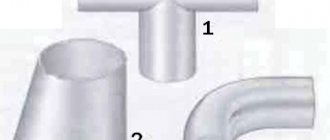
Valves are pipe fittings with a valve in the form of a flat or conical disc, which moves reciprocally along the central axis of the sealing surface of the body seat.Valves also include fittings (rotary valves), in which a disc-shaped shutter moves in an arc. The arc described by the center of the valve is tangent to the axis of the seat, the center of the arc is outside the seat bore, and the axis of rotation of the valve is perpendicular to the axis of the medium flow.
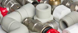
Popular Flanged Valve Models
Today there are several types of shut-off valves. It all depends on which method is used in order to overlap the working environment. The list of popular models includes the following mechanisms:
- screw;
- gate;
- ball;
- cork.
On screwed parts, the movable valve is fastened with a screw connection. It must be pressed against the seat, which is located in the master cylinder of the valve. The stuffing box packing is represented by a sealing washer, which ensures the tightness of the device.
The specific disadvantages of the mechanism include the fact that it passes water in only one direction, and its rubber or paronite tubes periodically wear out and need to be replaced. If sand or scale enters the cylinder, the gaskets can be completely or partially destroyed.
The gate valves are very similar in design to a gate valve, as their threaded stem facilitates the deflation of the tapered valve between the two mirrors. Instead of stuffing box packing, you can install seals made of rubber or polymer clay, which differ in service life over a long period of time.
For the manufacture of ball flange fittings, brass or stainless steel is used, and the design is a ball with through holes. The rotation of the handle ensures rotation of the ball in the valve cylinder, and its fixation is carried out using a pair of annular seats made of Teflon or fluoroplastic. It is recommended to use the same material for sealing.
Flanged plug valves are closed off by a conical plug fitted with a through hole. Typical problems with such devices include the fact that the packing must be changed periodically.
New modifications of the shut-off valve
For many years, proven devices and technologies have been used on the valve market, and new items appear quite rarely. However, newer and more sophisticated shut-off valves are already on the market and are in great demand. What is the innovation and design difference between old and new valve designs? Let's try to figure it out further.
New devices appearing on the market have the following set of advantages over the classic models of shut-off valves used for a long time:
- old type valves are not always able to cope with high loads created by mud flows and liquids with various impurities. Valves of a new type easily pass and retain contaminated water, without creating problems in the operation of the system;
- The tightness of the latest shut-off valves has been greatly improved by the installation of additional materials. As a result, the tightness of the system is several times higher than those provided by the valves of old modifications;
- the speed limit in case of emergency situations has been increased several times in new valve models - the response time in case of system failures and breakdowns is maximum 10 s;
- unlike the old valves of the stop valves, the new shut-off mechanisms are capable of shutting off the flow of liquid in the pipeline in two directions at once;
- In addition to the main parts, the latest valve modifications also include a silicone spring gasket and a unique adjusting washer.
The innovative design of convenient, durable and reliable shut-off valve systems is very popular and is actively used in modern filtration systems. Also, such valves have become indispensable in industrial enterprises - in the food, pulp and paper, energy sector.